Project Category: Chemical

Join Our Presentation
April 5th 2022, 10:00AM – 12:30PM
About Our Project
Ammonia is a versatile chemical with uses in a wide variety of industries. It is used as a fertilizer, a refrigerant, an ingredient in household cleaners, fuel, and even energy storage. These uses allow ammonia to serve a plethora of industries, including agriculture, energy, and industrial chemical production. Alberta relies heavily on these industries in many ways, from furthering the province’s economy to providing reliable services for its citizens. Our company, NH3 Natural, has been contacted to explore the feasibility of an ammonia production plant in Alberta.
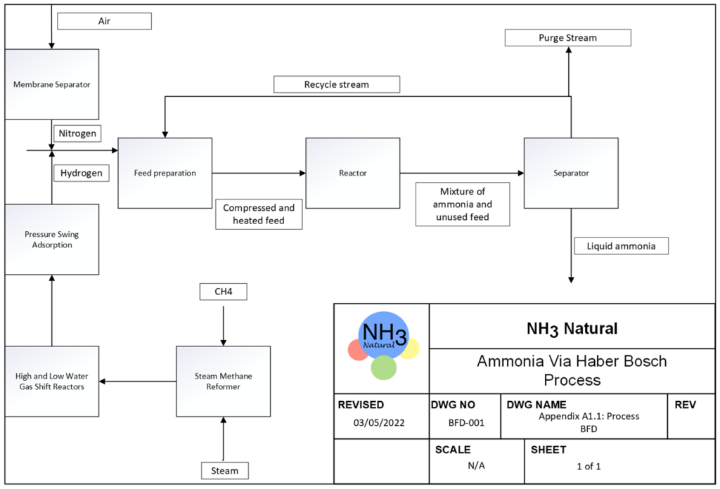
We plan to produce ammonia through the Haber process, where two raw materials, hydrogen and nitrogen, are obtained from steam methane reforming and membrane separation of air, respectively.
Meet Our Team Members


Details About Our Design
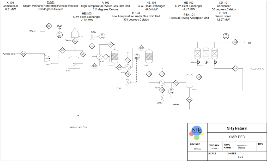
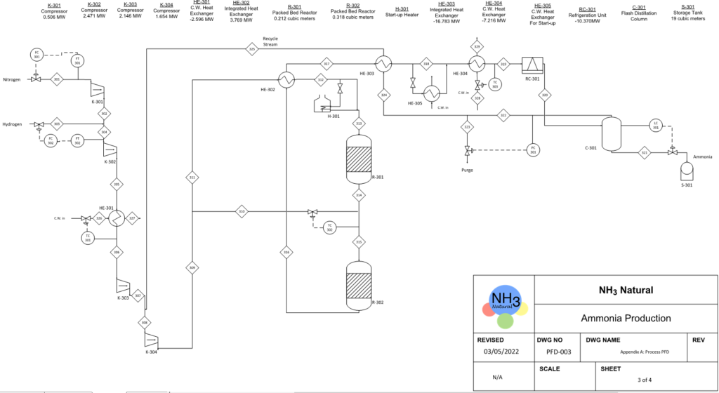
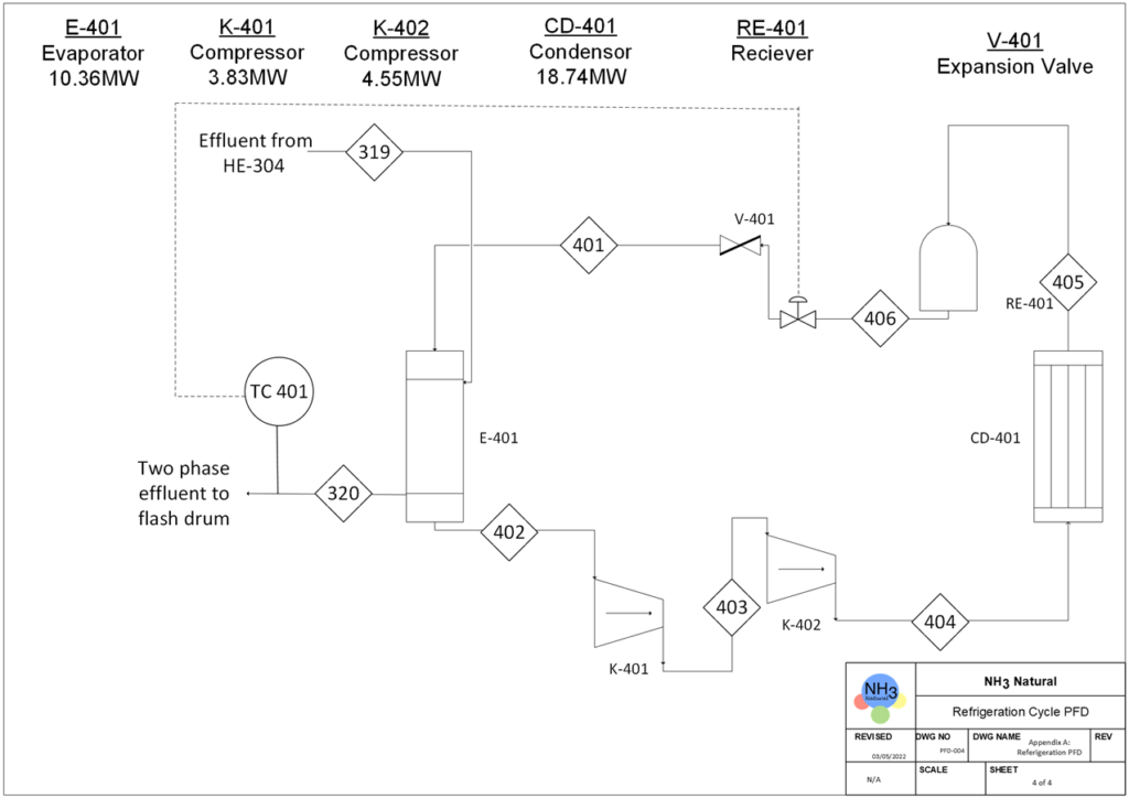
PROCESS OVERVIEW
BFD Of Our Process

WHAT MAKES OUR DESIGN INNOVATIVE
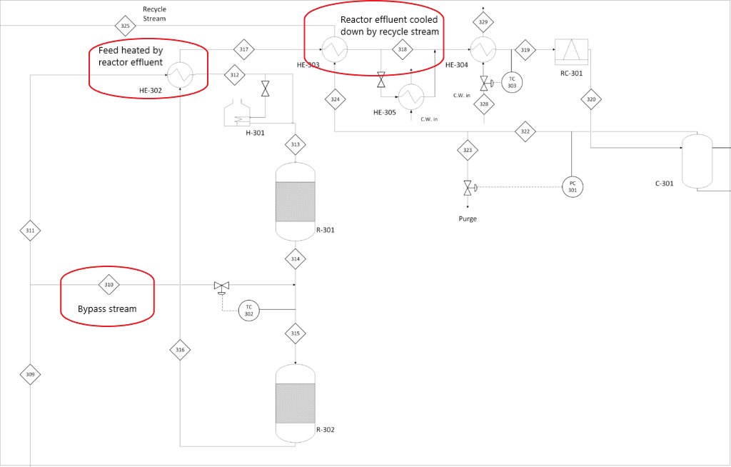
- Bypass stream in between reactors.
- Since the chemical reaction for the Haber process is highly exothermic, a relatively cold feed stream is split and mixed with the hot effluent from the first reactor increasing the single-pass conversion of nitrogen.
- Energy Optimization.
- To utilize the energy from the reaction, the effluent from reactors will be sent into the heat exchanger to heat up the feed stream entering the first reactor.
- The reactor effluent is cooled down by the feed stream and then further cooled down by the recycle stream which in return is heated to the desired temperature.
- Membrane Separation
- The membrane separation process is used in nitrogen generation on-site which is relatively safe and saves us on operating costs.
WHAT MAKES OUR DESIGN SOLUTION EFFECTIVE
Flash Drum
Vertical separator
Able to handle large surges of liquid, the absolute level doesn’t affect separation efficiency much, less chance of liquid re-entrainment, smaller footprint.
Inlet diverter
Momentum change from impact leads to the separation of liquid from vapour.
Mist extractor
Provides a large surface area to coalesce and remove small liquid droplets.

Membrane
The membrane has a cross-flow configuration with polysulfone fibres coated with polydimethylsiloxane at 3 wt % (PSF-3PDMS). The permeability of oxygen is much higher than the permeability of nitrogen, resulting in the separation of nitrogen from the air.
The optimal temperature and pressure of the feed are 28 ̊C and 4.935 atm respectively. The pressure of the permeate side is set at atmospheric pressure, therefore the driving force of the separation is the pressure difference.
Reactor
- Operating Condition Selection
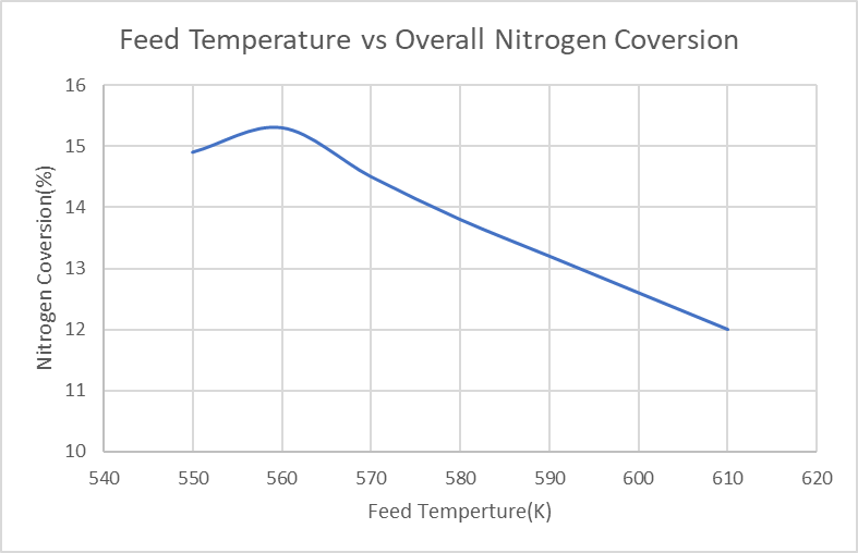
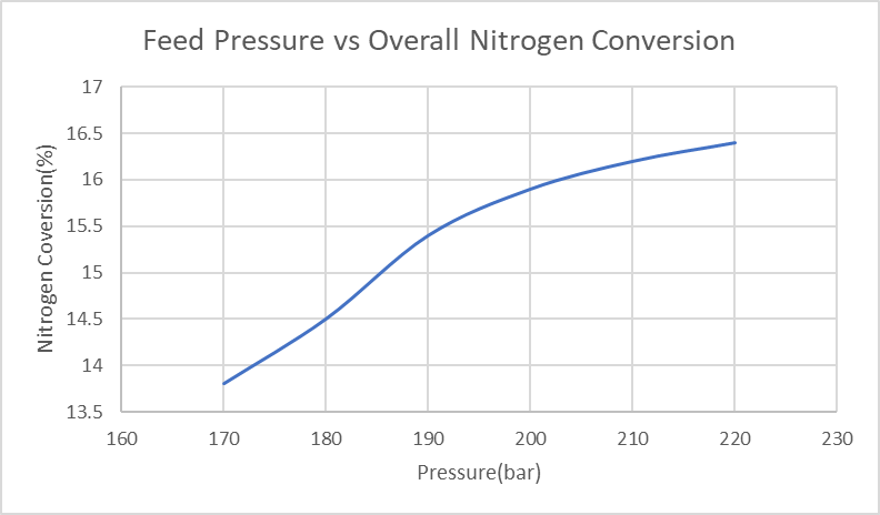
- The biggest challenge for our reactor design is to select the best operating temperature and pressure to achieve higher single-pass conversion (higher than 15%). As shown in Figure.1 below, indicated in our simulation results, the overall nitrogen conversion increase with the decrease of the feed temperature. However, when the feed temperature is lower than 560K, the conversion decreases; the reason is that if the temperature is too low, the equilibrium will not be able to reach the reactor. Finally, a feed temperature of 563K was selected to have the highest nitrogen conversion. Furthermore, as indicated in Figure.2, the overall nitrogen conversion increases with the increase of feed pressure; and the slope is more flattened after 190bar. In this case, a relatively high feed pressure needs to be chosen. However, for safety concerns, the operating pressure needs to be lower than 50% of the maximum design pressure for our reactor tubes, which is 3082.5psig to make sure the reactor can operate safely in the high-pressure condition; the final feed pressure is chosen to be 202.65bar/200atm, which is 2939psig.
- High Reactor Efficiency
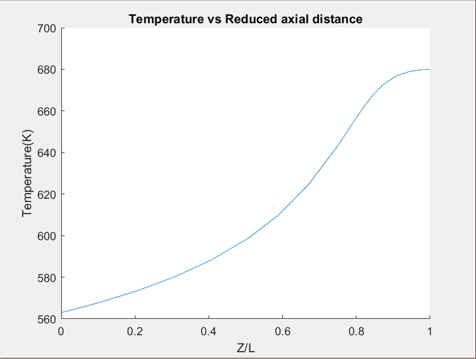
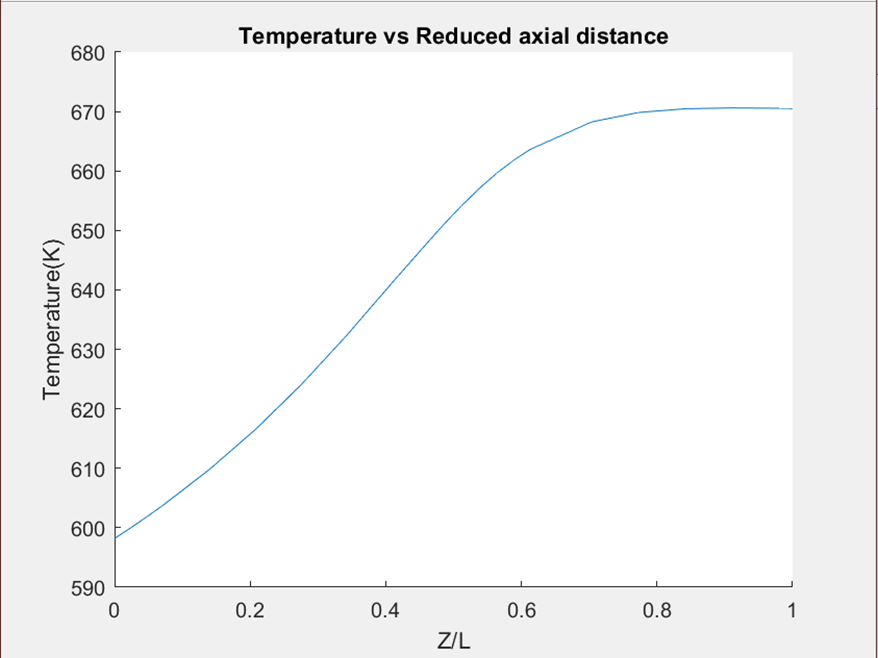
- Besides the single-pass conversion, another very important criterion for good reactor design is that the equilibrium of the reaction will be reached right before the outlet of the reactors, it will make sure the highest conversion is reached and no reactor length/volume was wasted. As shown in Figure.3 and Figure.4 below, the slope of the temperature turns zero before the outlet for both of our reactors which indicates the equilibrium is reached. Where Z is the graph indicates the length between a certain position and the inlet of the reactor, and L is the total length of the reactor.
- Catalyst Selection
- The Catalyst we’re using in the reactors is iron-based catalyst A110. The are three reasons that we chose the A110 as our catalyst, (Table.9.15 in Ammonia Synthesis Catalysts Innovation and Practice–Huazhang Liu)[5] Firstly, it has a low cost and a long life (10 years)[5]. More importantly, the predicted catalyst A110 has a very low reduction degree within the temperature range of our reactor (300⁰C~400⁰C), the hydrogen reduction reaction with our catalyst can be considered the minimum.
HOW WE VALIDATED OUR DESIGN SOLUTION
Flash Drum
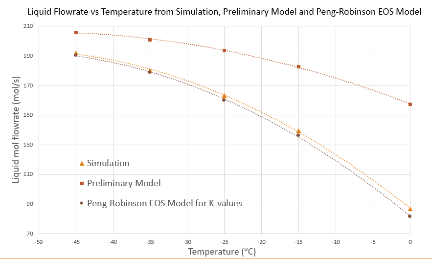
Molar Flowrates Calculation
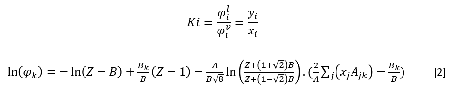
Using Peng-Robinson Equation of State
Fugacity coefficients to calculate K-values
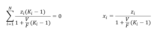
The Rachford-Rice equation to calculate mole fractions and molar flowrates

Sizing Calculation
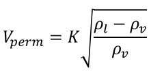
Souders-Brown Equation
Vapour velocity = 80% of maximum allowable vapour velocity
Residence time consideration
Hand calculations for sizing were verified with symmetry simulation.
Membrane
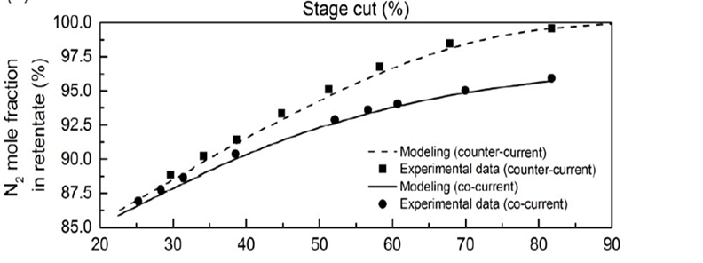
- The stage cut for a nitrogen purity of 99 % is 88 %, which was validated with Matlab, symmetry Process Simulation, and experimental data.

The local permeation rate over a differential membrane area dAm is given by [6]:

Dividing the two equations above gives the following equation which relates the retentate composition x with the permeate composition y [6]:

The analytical solution to the equations was obtained by Weller and Steiner using transformations.
Reactor
- Ideal PBR/PFR reactor
- We have to validate the PFR assumption before our reactor modelling, for an ideal PFR reactor, there will be perfect mixing in the radial direction while backward mixing in the axial direction. To make sure the assumption is valid we calculated the Reynolds number in our reactor Re=1.9*10^8, as the flow is highly turbulent, we can assume perfect mixing in the radial direction. At the same time, the packed bed in the reactor can prevent backward mixing in the reactor.
- Accurate Model
- For our reactor, we developed our model and simulate it with Matlab.
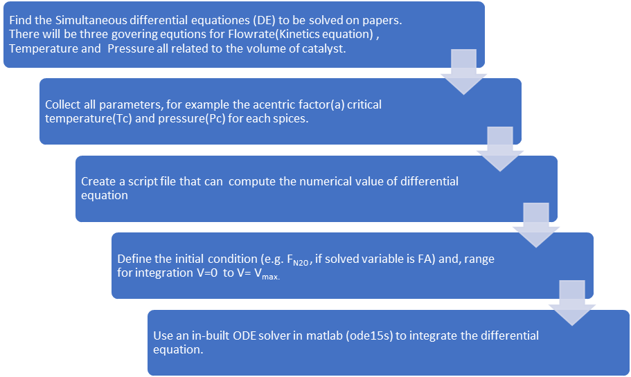
Following are three governing equations for the reactor model.
- Kinetics Equation And Mole Balance For Flowrate.

where Fi is the flow rate for each species inside the reactor.

Where -rN2 is the consumption rate of nitrogen, Pi is the partial pressure of each species, R is the gas constant, and T is the temperature in the reactor.
- Pressure Drop
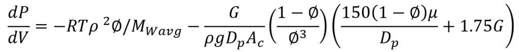
Where G is the mass velocity, g is the gravity acceleration constant, 𝜌 is the density of the gas, 𝜇 is the viscosity of the gas, Dp is the diameter for the catalyst particle and ∅ is the porosity of the catalyst.
- Energy Balance For Temperature.
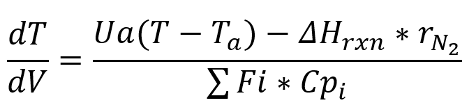
Where U is the overall heat transfer coefficient, a is the surface to volume ratio a=4/D, where D is the diameter of the reactor, ΔHrxn is the heat of reaction, and Cpi is the heat capacity for each species.
FEASIBILITY OF OUR DESIGN SOLUTION
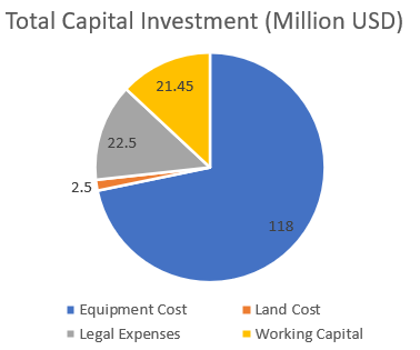

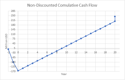

%ROR for base case = 8.1
Payout Period for base case = 6.3 years
%DCFRR for base case = 9.9
The selling price of ammonia has the most significant effect on profitability.
Partners And Mentors
We would like to thank our supervisor, Dr. Maen Husein, for his guidance and support throughout the last 8 months. We would also like to thank Dr. Hector Siegler for his constructive feedback.
Our Photo Gallery

References
- [1] Arnold, K.; Stewart, M. Design of Oil Handling Systems and Facilities, 3rd ed.; Elsevier: Amsterdam ; London, 2008.
- [2] Elliott, J.; Lira, C. Introductory chemical engineering thermodynamics; Prentice Hall: Upper Saddle River, NJ, 2012
- [3]Seider, W. D. Product and Process Design Principles: Synthesis, Analysis, and Evaluation; John Wiley & Sons: Hoboken, NJ, 2017.
- [4]Central Authentication Service. (n.d.). Retrieved April 2, 2022, from https://d2l.ucalgary.ca/d2l/le/content/357317/viewContent/4601858/View
- [5]Liu, H. (2015). An he Cheng Cui Hua Ji: Chuang Xin Yu Shi Jian = ammonia synthesis catalysts. Hua xue gong ye chu ban she.
- [6]Geankoplis, C. J. In Transport process and unit operations; Prentice-Hall : Engelwood Cliffs, N.J, 1995; pp 760–777.
