Project Category: Chemical
Join our presentation
Why upgrade bitumen in Alberta?
Worldwide demand for crude oil is expected to rise to 111 million bbl/d in 2040. Alberta is well placed to help meet this demand because of strong provincial government support for large oilfield infrastructure projects, extensive oil reserves, existing industry expertise, and the increasing demand for light synthetic crude oil by Gulf Coast and Asian markets.
Our proposed facility will be constructed in Sherwood Park, Alberta and will be capable of producing 90,000 bbl/day of sweet synthetic crude oil from a diluted Athabasca bitumen feedstock. The final synthetic crude has a 31 API density with less than 0.1 wt% sulphur and is comparable to other synthetic crude oils produced in the region such as Syncrude Sweet Premium blend. This upgrader will utilize a fluidized bed thermal coker with gasification to achieve an overall conversion of 98.5% of all bitumen feedstock. Approximately 75% of the bitumen feedstock is converted into a high-quality SCO and 23.5% is converted to syngas. The combined thermal coking and gasification process has a greater product yield, lower utility requirements and fewer environmental impacts than a traditional upgrading facility utilizing technology such as delayed coking.
Meet our team members


What makes our design effective?
The incorporation of a thermal cracking fluidized bed coker with gasification allows for the highest amount of bitumen conversion with the highest safety considerations. The fluidized bed reactor converts 75% of the bitumen feed into lighter ends that are then hydrotreated and blended into the synthetic crude oil product. The gasifier can then convert 98.5% of the remaining coke by-product from the fluidized bed reactor into useful syngas. This syngas is then separated into a hydrogen source and the carbon monoxide can be used as a low heating value fuel gas. This design produced more hydrogen than is required for hydrotreating allowing the upgrader to be an overall producer of hydrogen.
This process is similar to other upgraders in Alberta with the addition of a gasification reactor. It was determined not to use a hydrocracker reactor in this stand-alone upgrader because of safety considerations. A hydrocracker is highly exothermic while a thermal cracker, such as this design, is endothermic and is less prone to process upsets. It should be noted that a hydrocracking design with gasification was designed in Alberta where multiple fatalities occurred due to process complications due to hydrocracking. The thermal cracking design also lowers initial capital cost.
Process Overview
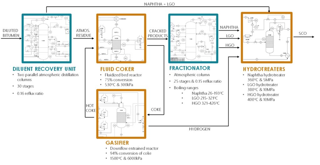
This bitumen upgrading design consists of five major units:
- Diluent Recovery Unit – Atmospheric distillation recovers diluent which is recycled back to the production facility. Also recovers high-quality distillate such as Kerosene and Light Gas Oil.
- Fluidized Bed Thermal Coker – The most crucial step in upgrading bitumen occurs in the fluid coker where heavy, complex long-chain hydrocarbon molecules are cracked into shorter-chain, simpler hydrocarbons.
- Gasifier – Gasification of the petroleum coke by-product creates syngas which provides the hydrogen necessary for hydrotreatment. Excess coke is recycled to the Coker.
- Fractionator – The fractionator separates the cracked products from the fluidized bed reactor based on boiling point so that each fraction can be hydrotreated individually.
- Hydrotreatment – This is the final stage of upgrading where sulphur, nitrogen, and oxygen atoms are removed as well as the saturation of aromatics that lighten and purify the crude oil. After hydrotreatment the final purity and after blending a final API of 32 is achieved.
Design Overview
Diluent Recovery Unit (DRU)
Distillation separates different fractions present in the diluted bitumen by the virtue of different boiling points between each fraction. Diluted bitumen is pre-heated and pumped to DRU in which lighter fractions of the feed including the diluent are recovered with distillation. The tower consists of a partial condenser with no reboiler, 30 trays, 3 pump-arounds, 2 side strippers and a reflux ratio of 0.16. The feed is fed at the bottom of the tower at Tray 29 and about 20.7% of the feed is recovered as diluent. The temperature profile increases from 165.0℃ at the top to 345℃ at the bottom. The lightest fractions such as water, diluent and light-end gases are recovered in the partial condenser, whereas kerosene and light gas oil (LGO) are recovered in lower parts of the tower. The recovered fractions such as naphtha, kerosene and LGO are sent to the appropriate hydrotreaters for secondary upgrading.5 The heavier fractions that remain, called the atmospheric residue, are recovered as the bottom product and pumped to the fluidized bed reactor for coking.
| Parameter | Value |
| Column Diameter (m) | 4.2 |
| Column Height (m) | 36 |
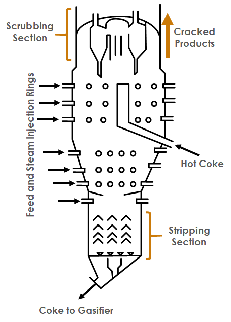
Fluidized Coking Reactor
The primary upgrading reactions occur in the fluidized bed reactor (R-200) which cracks long hydrocarbon chains present in the atmospheric residue from the DRU. The atmospheric residue feed is thermally cracked into sour naphtha, light and heavy gas oil products along with coke residue and an assortment of light ends. The reactor converts 93 wt% of maltenes and 57 wt% of asphaltenes for a total conversion of 75 wt% of the atmospheric residue. This thermal coker reactor operates at 530℃, and 300 kPa. The fluidized bed reactor has concentric nozzles at varying heights that inject the steam and feed which create a well-mixed highly turbulent flow regime within R-200. These turbulent conditions allow for the reactants to be well mixed and make sure that the reactants are heated evenly throughout the fluidized bed.
The 25 wt% of coke residue is then sent in a water slurry to the gasifier (R-300). After gasification hot coke particles are recycled back into the fluidized bed coker (R-200) to provide a portion of the heat requirements of the reactor. These hot coke particles also act as nuclei for thermal cracking, where atmospheric residue particles attach to the surface of the coke particles on which coking occurs. Both thermal cracking and gasification are endothermic processes where the reactants are heated externally with gas-fired heaters.
| Parameter | Value |
| Volume (m3) | 134 |
| Reactor Diameter & Length (m) | D = 3.35, h = 15.30 |
| Heat of Reaction (GJ/h) | 652 |
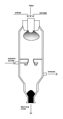
Gasifier
The coke residue from the Fluid Coker (R-200) is sent to the Gasifier (R-300). This gasification reactor converts 94% of the coke by-product into syngas consisting of carbon monoxide and hydrogen by reacting the coke with steam and oxygen. The reactants are heated up to a temperature of 1500℃ before entering R-300 which operates at a pressure of 6 MPa with a residence time of 2 seconds. These reaction conditions promote gasification and limit undesirable combustion reactions that produce carbon dioxide. The syngas leaves R-300 and is cooled to a temperature of 80℃ before entering a two-phase separator to remove any suspended particulates. This syngas provides the excess hydrogen requirement necessary for hydrotreatment. The unreacted coke particles fall to the bottom of the reactor where they are quenched with fresh water and transported as a slurry for disposal. A portion of the unreacted coke (19%) is heated to 530℃ using a fired heater and then recycled to the Fluid Coker (R-200) which acts as a heating medium and acts as a thermal cracking reaction site.
| Parameter | Value |
| Volume (m3) | 95 |
| Reactor Diameter & Length (m) | D = 4.47, h = 6.04 |
| Heat of Reaction (MJ/h) | 119 |
Hydrotreatment Units
The final upgrading step occurs in the three hydrotreatment units, one for each of the oil fractions; naphtha, LGO and HGO coming from the fractionation column. The main objective of the hydrotreatment units is to remove heteroatoms through hydrodesulfurization and hydrodenitrogenation while also saturating aromatic compounds to lighten and purify each oil fraction. Each hydrotreater is a downflow fixed bed reactor with multiple catalyst beds composed of a NiMo/Al2O3 catalyst. Between each catalytic bed is a cold hydrogen quench to limit temperature rise during the exothermic reaction to less than 20℃. Operating temperatures range from 360-380℃ with operating pressures from 5-10 MPa. The excess hydrogen ratio varies from 10-40 Nm3 H2 per m3 of oil depending upon the density of the fraction being treated. This hydrotreatment design removes over 99 wt% of sulfur and 90 wt% of nitrogen impurities. After hydrotreatment the density of the blended crude oil is 31-33 API with less than 0.1 wt% sulfur.
| Parameters | Naphtha | LGO | HGO |
| Capacity (bbl/d) | 25000 | 32500 | 32500 |
| Sizing (DxL, m) | 3×19 | 5×19 | 5×19 |
| Superficial Velocity (kg/m2s) | 5.09 | 4.01 | 3.82 |
| Number of Catalyst Beds | 2 | 3 | 3 |
| Length of each Catalyst Bed (m) | 8 | 5 | 5 |
| Catalyst Weight (tonne) | 107 | 178 | 178 |
| Enthalpy of Reaction (MJ/h) | 50000 | 68500 | 70500 |
Fractionator
The cracked oil products leaving the Coker (R-200) must be separated in a fractionator (T-400) before being sent to hydrotreatment. T-400 is an atmospheric distillation tower with 25 stages, a partial condenser, and a side stripper. The tower operates with a reflux ratio of 0.15 and separates the components according to the boiling points of naphtha (26-193℃), LGO (215-321℃) and HGO (321-426℃).
| Parameter | Value |
| Column Diameter (m) | 4.5 |
| Column Height (m) | 28 |
Design Optimizations
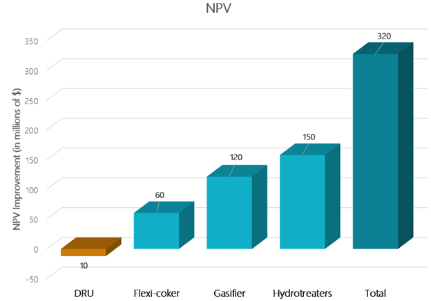
Compared with the first stage design of the bitumen upgrader presented in Design Basis Memorandum, the current design has undergone several changes which have led to significant improvements in Net Present Value (NPV) of the project. The design optimizations were implemented using the principles of heat integration. Pinch analysis ensured that as much heat transfer as was practically possible occurred between the cold and the hot streams. On top of heat integration, a few design changes such as implementation of a flash drum for DRU and air cooler for hydrotreaters led to further improvement in NPV of the project.
The overall NPV improvement of the project was approximately $320 million. The table below details the design changes and optimizations that have been implemented.
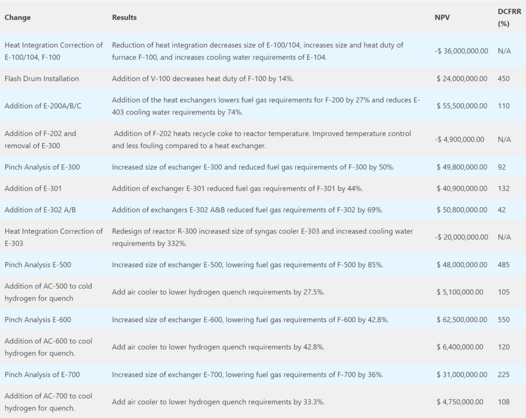
Below is a visual representation of the NPV changes due to design changes and optimizations. Note that NPV change due to DRU design changes is negative; previously, excessive heat integration had been assumed for DRU. Therefore, performing pinch analysis on DRU led to significantly increased costs, which negatively impacted NPV of the project.
Economics
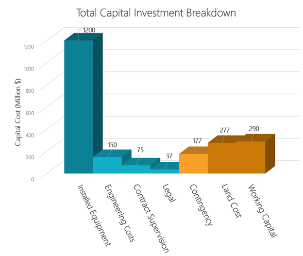
The total fixed capital of the project is approximately $2.2 billion including a working capital cost of $290 million and land cost of $270 million. Bare equipment costs were estimated using CAPCOST software. Installed equipment cost was then found using the Lang Factor Method. The final direct capital investment (DCI) was determined to be $1.2 billion. Indirect capital investment for engineering, supervision, legal and contingency were estimated as 10%, 5%, 2.5% and 10% of the DCI respectively. The project has been evaluated for a lifespan of 30 years and the economic assessment is based upon a plant operating reliability of 95% or 8320 hours per year. There are two main sources of revenue for the facility are the sale of synthetic crude oil (SCO) and hydrogen sales from the gasification process.
In the first full year of operation the sale of SCO and hydrogen amount to $1.75 billion and $225 million respectively. Overall non-operations expenses total to $650 million in the first year of operations. These expenses include provincial royalties, corporate tax, land tax, and the newly updated carbon tax.
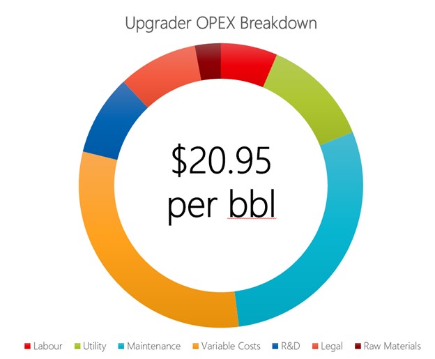
Operations cost (OPEX) for this facility is an estimated $650 million per year. This cost results in an estimated OPEX of $20.95/bbl of synthetic crude oil produced. This annual cost includes labor cost, maintenance (9% of FCI), raw material, utility cost and yearly overhead requirements (12.5% of SCO sales) that incorporate management of change, facility upgrades and administrative overhead.
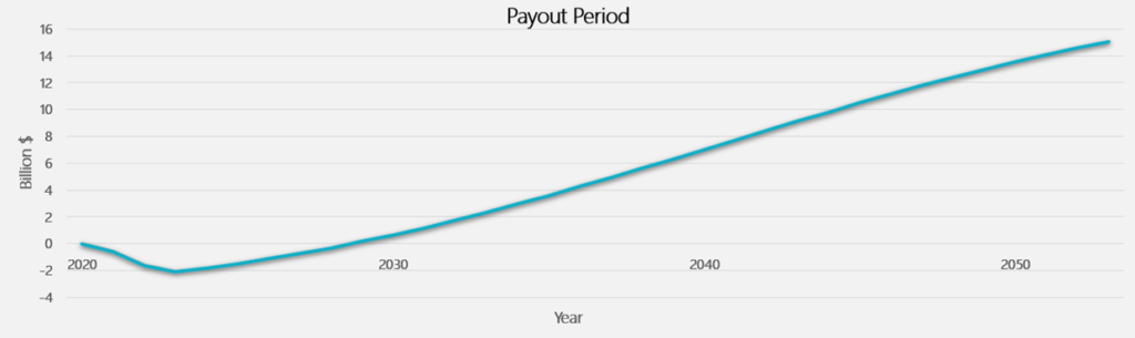
The payout period (POP) for this project was found to be 9.75 years as shown in payout period graph. The Net Present Value (NPV), return of investment (ROI) and discounted cash flow return rate (DCFRR) were found to be $8.8 billion, $571 and 17.5% respectively. Sensitivity analysis performed on the price of the WTI benchmark showed that the project would payout until an overall price reduction of 23% over the lifespan of the facility. The required WTI breakeven price for this facility is $46/bbl.
Environmental Impacts
Total annual carbon dioxide emissions from the facility are estimated to be 6990 tonnes per year. The overall process was optimized since to reduce CO2 emissions by 19% from the initial design. This reduction in overall emissions helps lower carbon tax payments by $640 million over the lifetime of the project as per the updated December 2020 Canadian carbon pricing. The three biggest contributors to emissions are the DRU, fluid coker, and the gasifier accounting for approximately 70% of the total emissions of the upgrader.
A 7500 m3 water reservoir with flow baffles has been added to ensure that the temperature differential for cooling water is less than 10°C. Overall, the upgrader requires 118,000 m3/d of cooling water, 26,000 GJ/d of natural gas, 316,000 kWh/d of electricity, and 1800 tonne/d of low, medium, and high-pressure steam. The waste leaving the upgrader will be managed in accordance with AER Directive 58 which sets the waste management requirements for upstream petroleum operations.As per AER D-060 a continuous flare system will be used to mitigate any emergency release of sour gases. This will limit off-lease odour in accordance with D-060 Section 8.8. Additionally, berms around storage tanks will be sized to 110% the capacity of the tank as per AER D-055 to ensure potential spills do not run off-lease.
Safety Considerations
Athabasca bitumen has a naturally high concentration of sulphur. The finished product is a sweet crude oil, with sulphurand hydrogen sulfide being the major by-products of the upgrading process. Due to the sour nature of the facility, all piping and equipment will be full sour specification. Sour service piping in the facility will have a minimum corrosion allowance of 3.0 mm to ensure equipment and piping longevity. This requirement makes 316 stainless-steel rated piping common for this facility in the presence of H2S. Additionally, higher nickel stainless-steel alloys are required for processes that are subject to hydrogen service. This higher alloy stainless helps to prevent critical failures caused by hydrogen cracking. All pressure vessels will have safety devices such as a pressure relief valve, temperature and pressure indicators to mitigate any safety risks with respect to high pressure and temperature. Furthermore, the by-pass for ESD valves will be car-sealed closed in addition to valves being car-sealed open which are directly in the path of a safety relief line such as a PSV.
To prevent personnel exposure to H2S and LELs a comprehensive gas detection system will be implemented. All areas of the upgrader will have H2S detection systems which will trigger an alarm at 5 ppm and a shutdown at 10 ppm. Additionally, there will be LEL detection systems with a high alarm at 20% with the shutdown at 40%. The presence of high temperatures and pressure will require additional site-specific precaution and personnel training. All personnel working at the facility will require a minimum of H2S Alive, WHMIS, TDG and CPC/AED level C training. Lastly, a detailed cause and effect LOPA method HAZOP will be performed to determine necessary safeguards, shutdowns, temperature and overpressure protection for the fluidized bed reactor and the diluent recovery unit. This HAZOP method assessed the risk levels of unmitigated scenarios to ensure appropriate safeguards are implemented for operational safety, integrity, and reliability.