Project Category: Chemical

COME JOIN OUR PRESENTATION
Team BioSYN’s presentation room will be active during the Engineering Capstone Design Fair
Tuesday April 5th, 2022 from 9:30am-1:30pm
About Our Project
Project Driver
In a society challenged by climate change effects and the finite nature of fossil fuels, biochemical generation from solid waste provides a viable pathway for a sustainable future. By the year 2029, the liquid biochemical market is anticipated to expand to 186 billion litres. These factors stimulate demand for energy solutions that not only minimize emissions but are optimized for safe operation and financial viability.
Our Solution
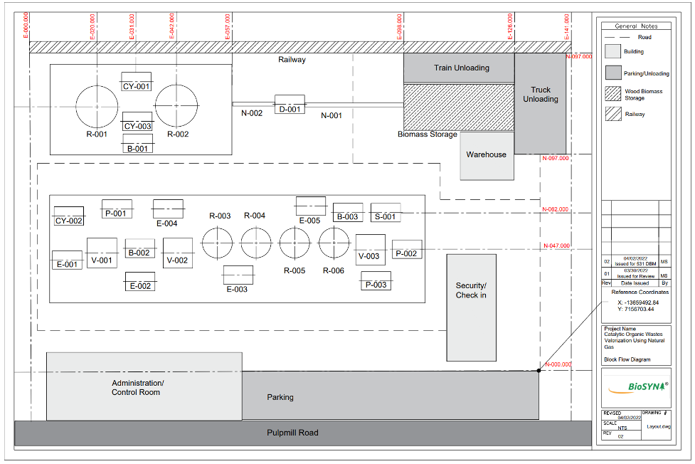
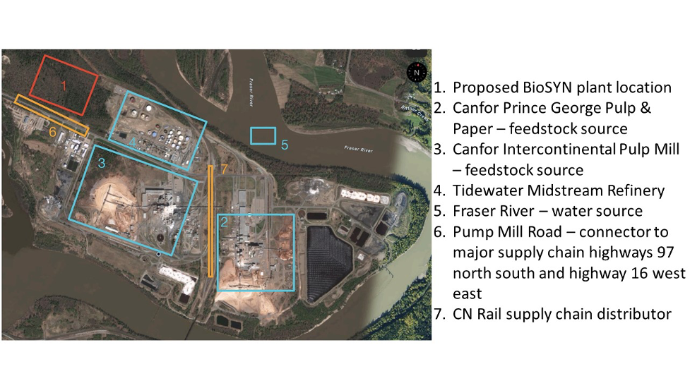
Team BioSYN has been tasked with developing an integrated catalytic process that can convert 100 tons per day of organic solid waste into usable liquid fuels and biochemicals with minimal by-product formation. Although applicable to various forms of organic waste, we have chosen biomass wood chips from forestry residue as our feedstock because it provides logistical and economic opportunities for our process. We have located our plant in Prince George, British Columbia, approximately 1.4km from the Intercontinental and Canfor Pulp Mills.
We are utilizing unique, innovative technology currently being researched by our mentor, Dr. Song, to rapidly pyrolyze (or thermally degrade) wood chips in the presence of natural gas. This methodology is referred to as Methanolysis, and provides an economical route to produce high-quality bio-oil from our feedstock. Downstream processes collect other light gases that cannot be quenched into bio-oil and react them further to produce additional desired products, including liquid toluene and para-xylene.


Details About Our Design
DETAILED DESIGN
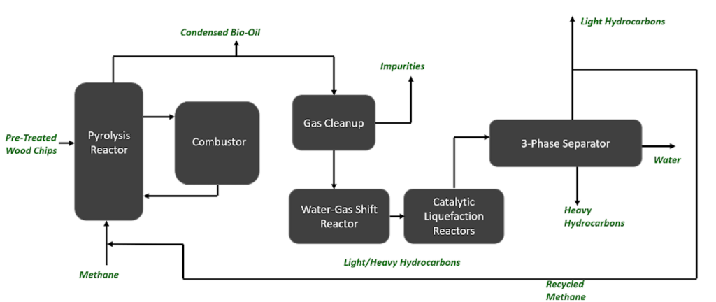
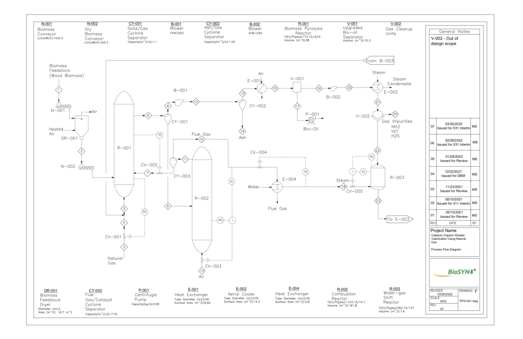
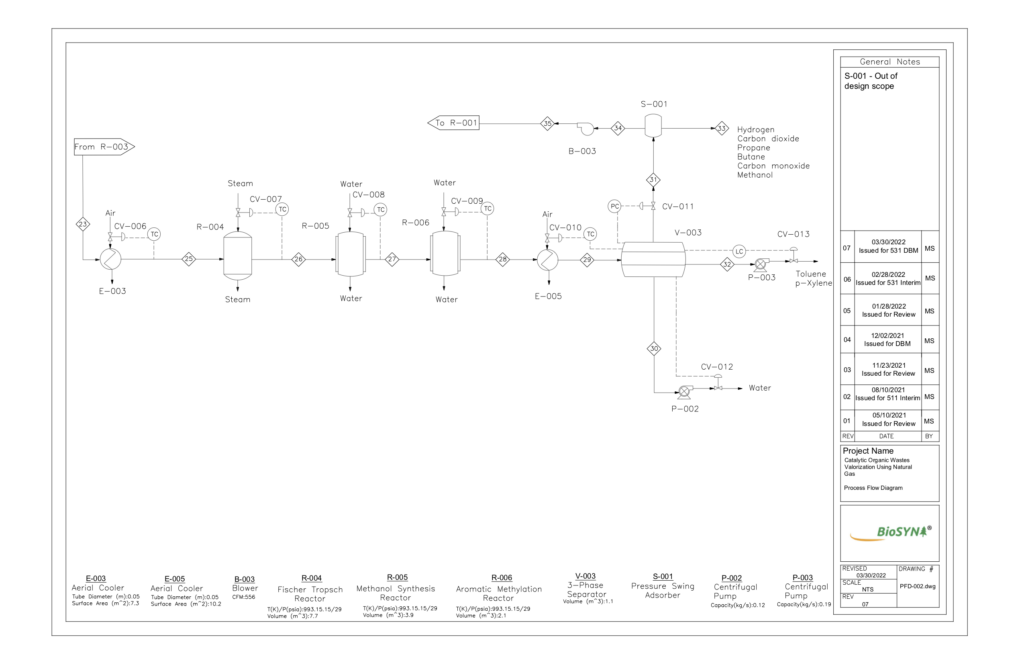
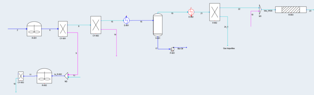
BioSYN’s process begins with a pyrolysis reactor that thermally degrades biomass pellets in the presence of natural gas. A catalyst is used for these reactions, and a combustor unit is used to regenerate and cycle the catalyst back to the pyrolysis reactor, like that of Fluid Catalytic Cracking technology. The desired products include condensable gases that are quenched to produce bio-oil, and non-condensable gases that are purified in the gas-cleanup units. These gases are reacted further in a Water-Gas Shift reactor to increase the hydrogen to carbon monoxide ratio. Light intermediate hydrocarbons are produced and upgraded in a series of catalytic liquefication reactors. Finally, the heavy hydrocarbons and separated into desired product streams using a 3-phase separator. Our major products from this separator include toluene and para-xylene. A recycle stream returns natural gas from the 3-phase separator to the pyrolysis reactor, which aids in cost saving and limiting greenhouse gas emissions.
BIOMASS FEED PRE-TREATMENT
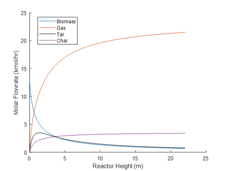
Pre-treatment is implemented to ensure uniform feedstock size for optimized heat transfer and desired moisture content. The role of particle size is an important factor for fast pyrolysis, a decrease in particle size reduces undesirable char yield and improves liquid yield. Chips and hog fuel enter the process at 5mm thick and 30mm long, optimal results are achieved when the wood particles are between 1-2mm. The initial screen transfers wood larger than 1/4” to an additional grinder while a secondary screen removes wood less than 1/8” as they do not require grinding before being pelletized. The particles between 1/4” and 1/8” are ground in a hammer mill into fine particulate. A pellet mill converts the ground material into pellets of uniform size with higher bulk and energy densities. The feedstock enters with an average moisture content of 44%. For pyrolysis and combustion to take place, the moisture content is decreased to 5% in a heated air rotary drier.
FAST PYROLYSIS REACTOR AND COMBUSTOR
The fast pyrolysis reactor and combustor consist of two circulating fluidized beds that exchange a HZSM-5 zeolite catalyst to facilitate methanolysis and provide heat to the endothermic pyrolysis reactions. Methanolysis is an essential step because natural gas acts as a hydrogen donor to aid in upgrading of heavier hydrocarbon product gases to be subsequently condensed into high-quality bio-oil. Fast pyrolysis favors the formation of bio-oil in a temperature range of 400-500oC, and residence times of 1.5-2.5 seconds. The zeolite catalyst has optimum thermal stability for gas-phase petrochemical and bio-renewable conversions.
Circulating fluidized bed reactors enable effective heat and mass transfer, which is essential to the production of various vapor products from the rapid heating of biomass. Particle size plays a large role in adequate fluidization, where both solid biomass pellets and catalyst are assumed to have diameters of 1-2mm. These reactors were designed to maintain flow of solids with a velocity high enough to entrain them with product gases. 316 Stainless Steel was chosen for reactor materials due to its resistance against corrosion, which has importance from a safety standpoint with the production of oxygenated volatile gases from pyrolysis.
CYCLONES
Three cyclones are present in the BioSYN process:
- The products stream exiting the pyrolysis reactor is separated by the first cyclone into gaseous products and solids. The gaseous products contain both condensable and non-condensable gases, including aldehydes, levoglucosan, phenols, and other aromatics. Solids consist of the HZSM-5 catalyst coated in biochar (solid carbon).
- The second cyclone further separates solid ash from the product gases before they are transported for cooling to collect the bio-oil product.
- Char is fully oxidized from the surface of the catalyst in the combustor. The regenerated catalyst is fed to the third cyclone to remove flue gas, then circulates back into the pyrolysis reactor.
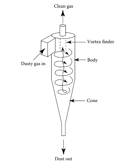
The cyclones use centrifugal force to separate particulate matter from the vapor streams. Air enters tangentially at the top of the barrel and travels down the cone of the cyclone to create the vortex. The increase of velocity in the vortex results in a centrifugal force on the particle which allows the solid to be removed from the stream. At the bottom of the cyclone, an inner vortex is created reversing direction and exiting out the top as product vapour or flue gas. The particulate falls out the bottom of the cyclone and is collected or recycled back into the process.
GAS CLEANUP UNITS
Various impurities containing ammonia, sulphur, and chlorine-based compounds have the potential to poison catalysts, corrode piping and equipment, and pose a safety issue if released to the atmosphere. Gas cleanup units are responsible for removal of impurities prior to gases entering downstream water gas-shift and catalytic liquefaction reactors.
- Sulfur removal has been industrially proven using zinc titanate regenerable sorbent. Non-generable sorbents include zinc oxide guard-bed and Sulfatreat iron oxide sorbent.
- Chlorine removal is accomplished using non-regenerable sodium-promoted alumina.
- H2S is present in the process in very low amounts. An economical removal option is the use of a ZnO guard-bed material such as BASF’s R5-12.
- Ammonia will be removed using wet scrubbing as it can deactivate catalysts.
- Sulfuric Acid is commonly used in scrubbers due to its availability and low cost. When ammonia is scrubbed with sulfuric acid it forms ammonium sulfate, which can be a profitable product if a high enough purity is attained. The sulfuric acid neutralizes the ammonia and forms the salt, which is then collected and removed.
WATER-GAS SHIFT REACTOR
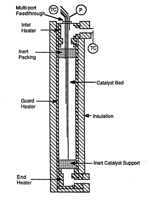
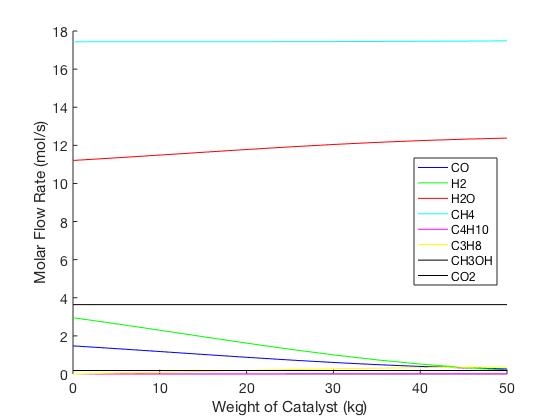
Non-condensable gases and water from the gas cleanup unit are fed into a High-Temperature Water-Gas Shift Reactor, which increases the conversion of high purity H2 through the shift reaction from CO to CO2. The reactor is being modelled as an adiabatic fixed bed to avoid overheating of catalyst due to exothermic reactions and improving the carbon conversion per catalyst weight. An iron-chromium oxide catalyst is being utilized due to its commonality in industry and size which limits the pressure drop across the bed while assuring a negligible mass transfer resistance.
CATALYTIC LIQUEFACTION REACTORS
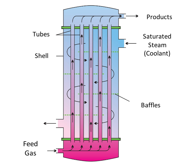
Three reactors can be found in series to conduct the upgrading and liquefication of the syngas stream exiting the Water-Gas Shift reactor. The first reactor is a multi-tubular packed bed reactor that facilitates the Fischer-Tropsch and Methane Co-aromatization reactions using two separated catalyst beds – Co/ZSM-5 and Zn/ZSM-5 catalysts. A stainless steel exterior with almost 2400 internal tubes promotes heat transfer from the highly exothermic reactions to a cooling stream running counter-currently.
The second reactor will be a fixed Cu/ZnO/Al2O3 bed to facilitate the methanol synthesis reactions. This set of reactions is important for the environmental contributions of the BioSYN process. By reacting the carbon dioxide and hydrogen found in the syngas stream to produce methanol, greenhouse gas emission rates of are greatly reduced and the removal of CO2 will also reduce the chance of equipment fouling in downstream process equipment.
Finally, another fixed bed will be found in series where Aromatic Methylation reactions occur. This reactor uses a H/ZSM-5 zeolite to upgrade the intermediate methanol with aromatics produced in the methane co-aromatization to produce the desired liquid biochemical – toluene and para-xylene.
THREE-PHASE SEPARATOR
Separation is accomplished by differences in density and is an ideal option for our process as the aromatic desired products have boiling points like that of water. Once the gas phase is separated, the liquids will be held for a residence time of 25 minutes to allow the light liquid to develop a distinct layer above the heavy liquid. The vapor is composed of CH4, C3H8, C4H10, CO, CO2, H2, and CH3OH. The light liquid stream is composed of C7H8 and C6H4(CH3)2. The heavy liquid is composed of water. To maintain consistency with industry, a pressure-swing adsorber was used to separate CH4 from the exit stream of the separator to be recycled back to the pyrolysis reactor.
HOW OUR DESIGN ADDRESSES PRACTICAL ISSUES
With the impacts of climate change resonating around the globe, it is becoming increasingly important for industries to seek renewable energy and chemical production pathways. Toluene and para-xylene are valuable commodities in the chemical industry that can be used anywhere from a fuel additive in the transportation sector, to a solvent in pharmaceuticals. BioSYN provides a net low emission process to manufacture these marketable products, paving the way for a brighter future in alternative energy.
Bio-fuel production from various biomass feedstocks has the potential of causing indirect land use changes. Land previously used for food or other crops becomes repurposed to sustain the feedstock, meaning these crops must be grown elsewhere. This results in indirect environmental disturbances to clear and harvest additional land overall. BioSYN acknowledges this challenge and addresses it by sourcing feedstocks from residual forest waste of pulp mill operations that is otherwise burned or discarded. This extends our development of a low emission process upstream of our plant life-cycle.
Pine beetle kill is a considerable issue for the forestry industry in Prince George and is a culprit for dry debris that causes forest fires. Over the next 2 decades, there will be a large surplus of low-value wood waste from Pine Beetle kill, estimated at 11 million dry tons/year. The harvested “beetle wood” is of lower quality and will not meet the standards for traditional wood, pulp, and paper products, increasing the amount of waste on the forest floor that can be repurposed as a biomass feedstock. In addition to pulp mill forestry waste, BioSYN can harvest this wood as an additional feedstock to produce the same high-quality bio-oil.
WHAT MAKES OUR DESIGN INNOVATIVE
Conventionally, bio-oil is created by pyrolysis or gasification technology but contains large mass fractions of water and oxygen with a low hydrogen-to-carbon ratio. The implications of this are a reduction in heating value, stability, fuel efficiency, and increased corrosiveness. Additional upgrading processes are typically performed to increase the quality of the bio-oil, like steam reforming, hydrotreating, or catalytic cracking. These processes are not only costly but increase design complexity and carbon footprint.
BioSYN integrates methanolysis technology, where natural gas is fed into our wood pyrolysis reactor to both create bio-oil components and upgrade them in “one step”. Wood enters the pyrolysis reactor and heats rapidly to produce several oxygen-containing vapors. Instead of sending them downstream for upgrading, natural gas provides a reducing environment to strip away oxygen from these vapors and replace it with hydrogen. Thus, bio-oil exits the reactor at a higher quality without the need for additional upgrading equipment.
Our process, however, doesn’t end there. Light gases that can’t be converted into bio-oil are taken downstream and converted into light hydrocarbons. Any methane leftover from pyrolysis is taken downstream with them and reacted further using methane co-aromatization technology. This innovation capitalizes on the synergistic effect between methane and light hydrocarbons under high temperatures to produce aromatic species like toluene. To increase safety in design, we have investigated a unique reaction pathway that can convert more toxic aromatics (like benzene) into comparably safer ones (like para-xylene) as a part of this step. Any methane still left unused is recycled back to the beginning of the process to limit greenhouse gas emissions and reduce operating costs.
The entire BioSYN process operates under 0.5 MPa pressures, allowing for significant environmental, economic, and safety benefits compared to other biomass-to-biochemical processes.
WHAT MAKES OUR DESIGN SOLUTION EFFECTIVE
BioSYN’s goal is to develop a process to lower the amount of greenhouse gas emissions, energy consumption, and cost of traditional aromatic production technologies.
Currently, the Intercontinental and Canfor Pulp Mills in Prince George, British Columbia, burn off residual wood waste from operations as hog fuel, amounting to 225 thousand tons per year. Hog fuel waste can instead be repurposed as BioSYN’s feedstock, in addition to the 17 million dry tons of sustainable forestry available in British Columbia per year. Sourcing feedstock from residual forestry waste eliminates the GHG emissions that would otherwise be released from hog fuel burning, and natural decomposition of other disposed wood products from mills.
BioSYN’s strategic plant location near these mills significantly reduces our transport costs for feedstock and utilities costs. Canfor operates with a steam plant nearby that our facility can tie-into, discounting costs of process steam. Methane used in the process can also be sourced economically from environmentally sustainable methods, such as decomposition and fermentation of municipal solid waste. Our process can also be adapted to all forms of organic solid waste including municipal feedstocks from landfills, increasing the span of our technology to other areas of the world.
HOW WE VALIDATED OUR DESIGN SOLUTION
An extensive literature review was conducted for every process reaction and piece of equipment for both the detailed design and general design to achieve the optimal efficiency, safety, and economic feasibility.
A simulation of our plant was generated using VGM Symmetry software. Multiple hand calculations were conducted for each piece of detailed design equipment to validate if the simulated Symmetry model that BioSYN developed was feasible. Process optimization techniques were executed to improve the accuracy of simulation results and refine design assumptions.
MATLAB code was developed for the three reactors in the BioSYN process to represent a dynamic model of the molar flow rate, pressure drop and temperature change along the length of the reactors using developed kinetic parameters.
All detailed equipment design has been cross-referenced with similar technology currently used in industry to ensure that our plant operates within realistic and practical bounds.
FEASIBILITY OF OUR DESIGN SOLUTION
We have performed an economic analysis of our design to assess the feasibility of this innovative project. A capital cost estimation reveals that the total capital investment required to construct the plant is $47.7 million, with a discounted payback period of 5.2 years. We anticipate annual revenues of $37.8 million from our primary products of bio-oil, toluene, and para-xylene. Our analysis also shows a net present value of $49.6 million, indicating financial viability.
Partners and Mentors
The success of our project would not have been achieved without the support and guidance of our mentor Dr. Hua Song, who has provided incredible insight and feedback with his expertise in organic waste valorization research.
Our Photo Gallery


References
[1] Prabir, B. Biomass Gasification, Pyrolysis and Torrefaction : Practical Design and Theory; Elsevier Science & Technology, 2013; pp 147-173. https://ebookcentral-proquest-com.ezproxy.lib.ucalgary.ca/lib/ucalgary-ebooks/detail.action?docID=1319046#
[2] Ahmed, I.; Anjum Zia, M.; Afzal, H.; Ahmed, S.; Ahmad, M.; Akram, Z.; Sher, F.; Iqbal, H. M. N. Socio-Economic and Environmental Impacts of Biomass Valorisation: A Strategic Drive for Sustainable Bioeconomy. Sustainability. 2022, 13(8), pp 1-32. DOI: https://doi.org/10.3390/su13084200
[3] Estimated Production, Consumption and Surplus Mill Wood Residues in Canada. Government of Canada. 2004. https://publications.gc.ca/collections/Collection/Fo4-7-2004E.pdf
[4] Xylenes (mixed isomers). Canadian Centre of Occupational Health and Safety. 2022.https://www.ccohs.ca/oshanswers/chemicals/chem_profiles/benzene.html#:~:text=What%20is%20the%20WHMIS%201988%20classification%3F%20B2%20-,irritant%3B%20Eye%20irritant%29%20Class%20B2%20Class%20D2A%3B%20D2B
[5] Toluene. Canadian Centre of Occupational Health and Safety. 2022. https://www.ccohs.ca/oshanswers/chemicals/chem_profiles/benzene.html#:~:text=What%20is%20the%20WHMIS%201988%20classification%3F%20B2%20-,irritant%3B%20Eye%20irritant%29%20Class%20B2%20Class%20D2A%3B%20D2B
[6] Clean fuels – fueling the future; Government of Canada, Oct 20, 2021. https://www.nrcan.gc.ca/our-natural-resources/energy-sources-distribution/clean-fuels-fueling-the-future/23735
[7] Canada’s Energy Future: Results. Canadian Energy Regulator (CER), 2021. https://www.cer-rec.gc.ca/en/data-analysis/canada-energy-future/2020/results/index.html#:~:text=Biofuel%20demands%20increase%20from%2090,2018%2C%20to%20112%20in%202050.
[8] Gill, M; Kurian, V; Kumar, A; Stenzel, F; Hornung, A; Gupta, R; Thermo-catalytic reforming of alberta-based biomass feedstock to produce biofuels, Biomass and Bioenergy, Volume 152, 2021, DOI:10.1016/j.biombioe.2021.106203
[9] All the Right Moves. Biomass. 2014. http://biomassmagazine.com/articles/10845/all-the-right-moves
[10] Biomass Handling – Storage Pile Basics. Advanced Biomass Consulting Inc. Nov 20, 2011.https://www.advancedbiomass.com/2011/11/biomass-storage-pile-basics/
[11] Environmental Management Act of British Columbia, 2021. https://www.bclaws.gov.bc.ca/civix/document/id/complete/statreg/03053_01
