Project Category: Chemical
Join our Presentation with the Button Below
Available from 10:00 am -12:30 pm MDT on April 13, 2021
About our Project
Investments within Alberta’s oil and gas industry are currently being driven by the pressures of complying with environmental, social, and corporate governance regulations. With an emphasis being placed on establishing a better sense of social responsibility, stewardship, and environmental concern, major players within this industry are keen on setting emissions reduction targets or, in some cases, pledging to become net-zero emitters. For such goals to be met, a significant shift must occur not only through the optimization of current assets but also through the development of capital projects that significantly reduce end-product lifecycle emissions. Through the current abundance of low-cost natural gas and carbon dioxide obtained through various carbon capture projects currently operating within the province, Alberta is in a unique position to develop and implement innovative solutions within the sector by leveraging existing carbon dioxide transportation infrastructure and technical knowledge.
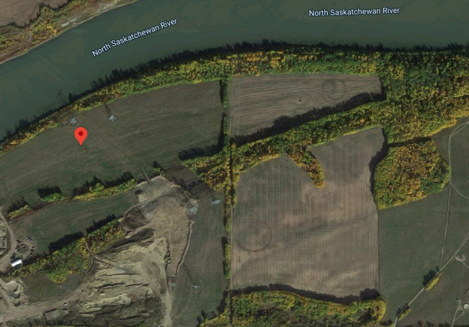
Through this project, we explore the viability of creating a plant capable of co-processing natural gas and carbon dioxide into synthetic crude oil located in Fort Saskatchewan, Alberta. By using these feedstocks, we have investigated the feasibility of a process capable of producing sustainable hydrocarbon fuels with the potential to further decarbonize the Canadian oil and gas industry and cater to the needs of Alberta’s current economic landscape.
Meet our Team


Design Overview
The Fischer-Tropsch (FT) synthesis process provides a way to convert natural gas and carbon dioxide (obtained through current carbon capture technology) into synthetic crude oil. This makes it possible to produce synthetic hydrocarbon fuels with the potential to further decarbonize oil and gas production in Alberta. Therefore, to determine the feasibility of FT synthesis, ClarityCarbon has designed a plant to convert natural gas and 750 tonnes of carbon dioxide a day into high-quality synthetic crude oil products.
Our proposed plant has access to the Alberta Carbon Trunk Line and is located in Fort Saskatchewan, Alberta. The plant produces approximately 16,600 bbl/day of synthetic crude oil and the primary products are naphtha, diesel, and wax.
Market Analysis
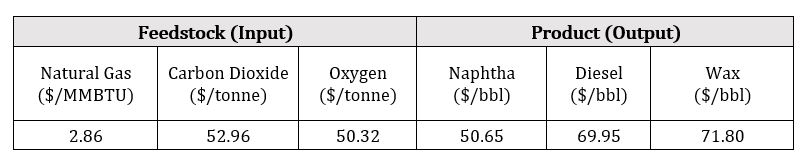
Natural gas consumption in Canada is expected to grow by 1.0 % per annum from 101.4 billion m3 in 2019 to 106.8 billion m3 in 2029*. The natural gas combined with carbon capture can provide a direct source of carbon-neutral fuels. Readily available natural gas and existing transportation infrastructure provides easily accessible and cheap feedstock for the FT-synthesis process. The pricing differentials between the feedstock and liquid hydrocarbon products, typically naphtha and diesel, are what drives the economics for the FT-synthesis process. The table below summarizes the feedstock and product prices used for the calculations in 2020 Canadian dollars.
There are three local refineries that could potentially purchase and upgrade FT-synthesis products: Imperial Oil’s 187,000 bbl/day Strathcona refinery, Suncor’s 142,000 bbl/day Edmonton plant, and Shell’s 100,000 bbl/day Scotford refinery*. The total capacity for these refineries is 429,000 bbl/day and our co-processing plant can provide an additional 16,600 bbl/day of feedstock to these Edmonton-based refineries and therefore capture up to 3.9% of the market. Furthermore, refining capacity is projected to increase by 0.4 MM bbl/day over the next decade in North America and Western Europe due to rising demand for low-sulfur diesel and bunker fuel to meet increasingly stringent regulatory requirements*. These conditions can therefore provide a unique opportunity to profitably produce liquid hydrocarbon fuels at a substantially reduced environmental impact.
*Natural gas consumption projections and local market data obtained from Fitch Solutions Group Limited, “Canada Oil & Gas Report,” London, 2020.
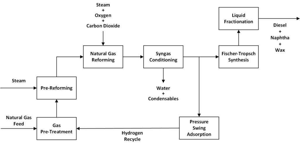
Process Description
To take a look at our design in detail, please view our supplementary diagrams using the buttons above.
Gas Pre-Treatment
Our natural gas feed contains contaminants such as thiols and sulfides. These sulfur compounds can poison catalysts and reduce equipment reliability, hurting our safety and bottom-line. Gas pre-treatment is used to remove these sulfur contaminants. Our plant’s gas treatment area consists of 2 major units, a hydrotreater, and a sulfur adsorber. Once treated, natural gas is sent to the reformer units.
Hydrotreater – Fixed-bed reactor using Co-Mo catalyst to hydrodesulfurize natural gas and produce easily removed hydrogen sulfide. Uses hydrogen from the pressure swing adsorbers.
Sulfur Adsorber – Packed bed adsorption column filled with zinc oxide adsorbent. Zinc oxide reacts with and traps hydrogen sulfide from the natural gas.
Pre-Reforming
Our natural gas contains larger hydrocarbons such as propane and hexane. These larger hydrocarbons can cause excessive coking on the reformer catalysts. To mitigate this coking, our plant uses an adiabatic pre-reformer.
Adiabatic Pre-reformer – Tubular packed-bed reactor using a Ni-Mg-Al catalyst. Reforms larger hydrocarbons into synthesis gas at relatively low temperatures. Requires a steam feed.
Natural Gas Reforming
The natural gas reforming area of the plant produces syngas which can be used to produce liquid fuels through Fischer-Tropsch synthesis. The reforming area consists of 3 major units; an autothermal reformer, a dry reformer and a catalyst regenerator. This section of our plant can be characterized by its high temperatures and pressures.
Autothermal Reformer – 2-section reactor consisting of a combustion chamber and burner, and a fixed-bed catalytic section. Requires oxygen and steam feed.
Dry Reformer – Continuous fluidized bed reactor using a Ni-Mg-Al catalyst. Co-processes carbon dioxide and natural gas to produce synthesis gas. Operates in a loop with the catalyst regenerator.
Catalyst Regenerator – Continuous fluidized-bed that uses combustion air to decoke the dry reformer catalyst. The regenerated catalyst is fed back to the dry reformer.
Syngas Conditioning
The produced syngas contains catalyst fines, unreacted steam, and trace amounts of carbon dioxide. These compounds can negatively affect downstream equipment and affect reliability. To remove these compounds and condition the syngas, a wet scrubber was installed.
Wet Scrubber – High-efficiency Venturi scrubber. A Venturi scrubber was used due to its effective removal of small particles such as catalyst fines.
Pressure Swing Adsorption
Our process produces an excess of hydrogen. Hydrogen is separated from the syngas through the use of pressure swing adsorption units. A portion of the separated hydrogen is recycled back to the hydrotreater and the remainder is sold.
Pressure Swing Adsorber – Adsorption column using zeolite-based adsorbent for its high selectivity to carbon monoxide and carbon dioxide. Separates hydrogen from the syngas and recycles it to the hydrotreater.
Fischer-Tropsch Synthesis
The heart of our process is the Fischer-Tropsch synthesis area where syngas is converted into liquid fuels. The Fischer-Tropsch unit consists of a slurry reactor and auxiliary units such as hydrocyclones and three-phase separators. The hydrocyclones separate the valuable Fischer-Tropsch liquids from the catalyst-rich slurry. Fischer-Tropsch synthesis produces a large amount of water. To separate the hydrocarbons from the water, a three-phase separator was used.
Fischer-Tropsch Reactor – A slurry reactor that uses cobalt low-temperature Fischer-Tropsch technology. Produces high quantities of liquid naphtha and diesel products.
Liquid Fractionation
To separate the Fischer-Tropsch liquids into end-user products, our process uses an atmospheric fractionator. First, the Fischer-Tropsch liquids are preheated using a fired heater. The hot liquids are then fed into the fractionator and separated based on their volatilities. To reduce energy costs, our design uses the hot naphtha and diesel streams to help preheat the feed.
Fractionator – Atmospheric trayed fractionator with a partial condenser and a total reboiler.
Design Innovation
Parallel Reformers
Our parallel Dry Reformer and Autothermal Reformer design allows our plant to directly consume 15 million standard cubic meter-per-day of carbon dioxide (with the former) while maintaining a synthesis gas carbon monoxide to hydrogen ratio of 2 (with the latter). This is a combination of novel technologies with concurrent coking mitigation strategies that give our Fischer-Tropsch reactor the optimum feed it needs to convert 100% of the syngas to syncrude.
Dry Reformer and Catalyst Regeneration Configuration
Dry reforming reactors use a fluidized catalyst bed to co-process carbon dioxide with natural gas into synthesis gas at a 1:1 ratio. One reason this system is not used in many industrial applications is the high coking rates on the catalyst. However, we saw this as an opportunity to innovate, as dry reformers already require less energy than conventional steam reforming. Hence, we developed a decoking catalyst regeneration cycle around our main reactor. Our regenerator burns off coke while avoiding sintering, so production yields remain consistent through our daily operation. Since the reforming reaction is endothermic, the hot regenerated catalyst supplies heat to the gases when re-entering the loop – further reducing our plant heat/utility requirements.
FT Process Intensification
We conducted many case studies to spot the optimum operating conditions with our Fischer-Tropsch (FT) loop. This meant looking at a multivariable analysis of our recycle streams, condenser efficiency and catalyst pairing, then applying a homotopic transfer function on different parameters to find our operation sweet spots. By pairing low-temperature FT technologies with a cobalt/paraffin-yielding catalyst, we were to defer the unwanted water gas shift side reaction, giving us headroom to use this system for onsite steam generation.
Design Verification
To verify the design of our process, we used Symmetry, a process simulator, to validate and optimize our units. Due to the large number of gas-phase unit operations, the APR thermodynamic package was selected. The thermodynamic package was verified by comparing simulation data with literature values. A screenshot of our simulation flowsheet is shown below.
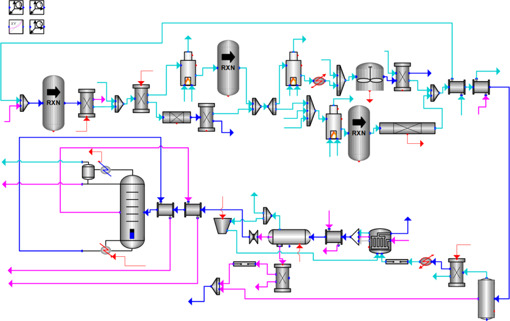
To double-check our simulation results, we also modeled select reactors on MATLAB. Simulation results were compared with MATLAB values to identify any deviations. Furthermore, we verified our equipment sizing by applying correlations and completing hand calculations. Where possible, we compared our values with literature sources and available industrial data, to ensure a feasible and successful design.
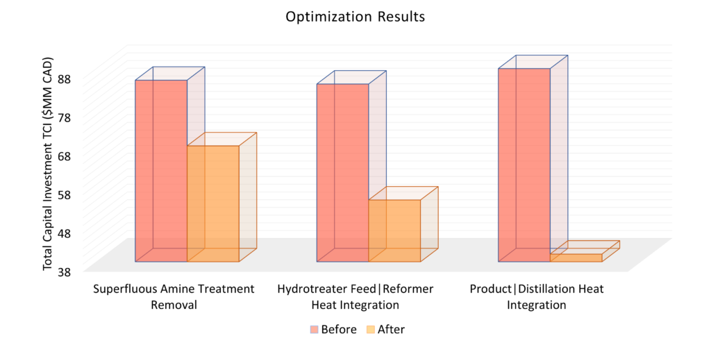
Process Optimization
For optimization, we looked at reducing our heating utility & total capital investment. Reducing heating utility minimizes our OPEX & environmental impact. By completing a pinch analysis on our heat exchangers & using our exothermic reactions to heat our process streams, we’ve significantly reduced our expenses – as demonstrated in the bar chart below. We also removed the amine treatment loop as carbon dioxide removal provides negligible process benefits.
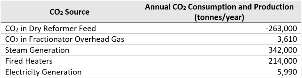
Environmental Impact
Due to the strong bonds present in the carbon dioxide molecule, natural gas and carbon dioxide co-processing requires a very large amount of energy. As a result, although our plant consumes a large amount of carbon dioxide, net emissions are actually 302,600 tonnes of carbon dioxide per year. Annual carbon dioxide consumption and production data is summarized in the table below. As shown in the summary table, steam generation is our most significant source of carbon dioxide.
For our 16,600 bbl/day co-processing plant, net carbon dioxide emissions are approximately 52 kg CO2/bbl. This compares with crude oil refinery emissions of 46-67 kg CO2/bbl as reported in the literature. However, it should be noted that our co-processing plant only produces an intermediate syncrude product. To create a final end-product, further upgrading of the syncrude will be required. The upgrading process will increase the net carbon dioxide emissions per barrel. Although our carbon dioxide co-processing plant is profitable, it also emits more carbon dioxide per barrel than a regular refinery.
Safety and Risk Analysis
In terms of feed streams, both natural gas and have safety risks. Inhalation of at low concentrations is not harmful but concentrations higher than 5000 ppm pose physiological risks. We will employ personal and stationary gas detectors to mitigate this risk. Natural gas is an extremely flammable gas and to mitigate fire risks, our ATR stream will be directly fed into the reactor to prevent unsafe combustion of natural gas. The presence of also poses a significant safety risk due to the toxicity of the gas. To ensure workers are not exposed to above the occupational exposure limit of 10 ppm, we will employ personal and stationary electronic detectors. Corrosion due to H2S poses another safety concern. To mitigate corrosion, ClarityCarbon will utilize corrosion-resistant materials in all units.
Our final products include naphtha, wax, and diesel; all of which are flammable, irritant, and carcinogenic. Care must be taken when handling FT waxes due to the risk of burns and vapors. As such, PPE such as coveralls, leather gloves, steel-toed boots and eye protection must be worn in affected areas. For product storage, several measures to ensure the plant safety will be implemented. Safeguards will include tank vents to reduce vapor emissions, spill containment berms, and keeping all storage tanks above ground and within dikes. The use of these preventative measures will mitigate spills, explosions, and pool fires. We will also ensure the tanks are separated by the recommended distance of 30 m to prevent chain explosions.
Our plant will have very high temperature gas streams. With regards to safety, containment will be achieved through preventative maintenance, and adequate insulation and material selection. Additionally, ClarityCarbon will employ the use of pressurized vessels which poses a potential safety risk to personnel on site. ClarityCarbon will follow the design codes as outlined by ASME Boiler and Pressure Vessel Code.
The nickel and cobalt FT catalyst used in our gas reformers has the potential to catch fire and cause an allergic reaction. As such, only professionals trained in handling toxic chemicals with the appropriate PPE will be authorized to handle catalysts. Repeated exposure to cobalt dust can cause scarring of the lungs which can be fatal. Thus, a breathing apparatus must be used in the affected area. Furthermore, alumina supports may form combustible dust concentrations in the air. To mitigate this, ClarityCarbon will ensure proper ventilation in all process areas.
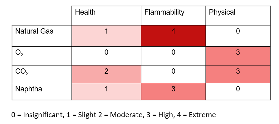
The following Risk Matrix summarizes risks for select chemicals in our process and will be used to conduct a more comprehensive safety analysis of our plant design:
Economics
Capital Expenditures
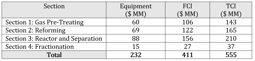
The total fixed capital investment (FCI) is $CAD 411 MM in 2020 dollars and the total capital investment (TCI) is $CAD 555 MM which includes the FCI, the working capital, and the start-up expenses. The capital costs for the project were broken down into direct, indirect, and contingency costs. The fixed capital investment was calculated by summing the direct, indirect, and contingency costs for every piece of equipment in the plant design. The cost estimates are expected to be within +/- 30% of the actual price. Prices are reported in Canadian dollars and as such, have been converted from US Dollars using a conversion factor of 1.00 USD to 1.34 CAD. A summary of the capital expenditure breakdown by section is shown below in 2020 Canadian dollars.
Operating Expenditures
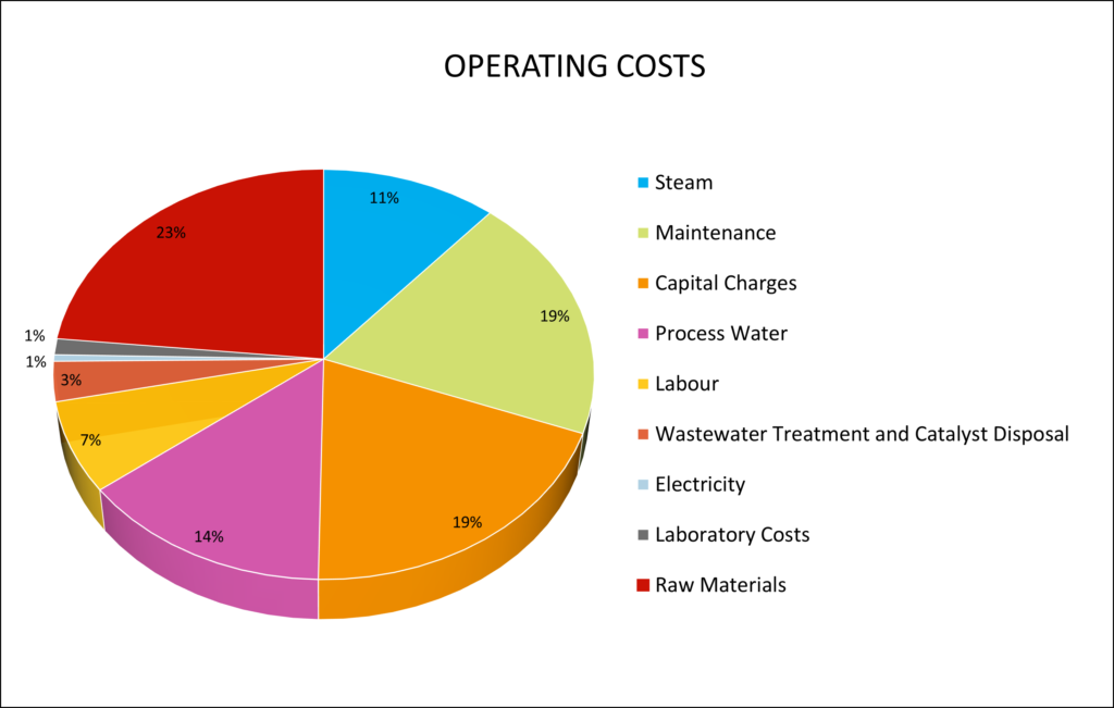
The total annual operating cost is estimated at $CAD 262 MM. This value includes utility costs such as steam production, process equipment electricity, and process and cooling water. The electricity and process water costs were taken from the City of Fort Saskatchewan. The other utility costs were calculated using a two-factor correlation developed by Ulrich and Vasudevan. This value also includes raw materials (natural gas, carbon dioxide, oxygen), wastewater treatment and catalyst disposal costs, and operating labour (engineering, supervisor, skilled labour). A breakdown of the total operating cost is shown using the pie chart below.
Financial Analysis
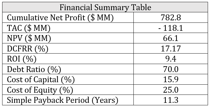
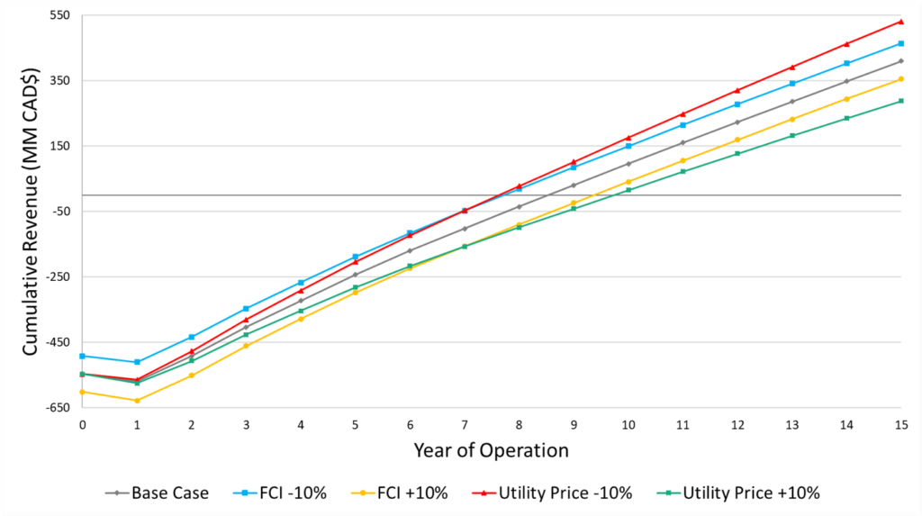
Financial calculations indicate an average annual net profit of CAD$52 MM with a cumulative return on investment (ROI) of 9.4%. The total annualized cost (TAC) is CAD$ 118.1 MM and the net present value (NPV) of the plant is CAD$66.1 MM. The product revenues were estimated through forecasted sales and feedstock prices based on historical data from 2020. The project lifetime was set to 15 years and the modified accelerated cost recovery system (MACRS) was used as the depreciation method. A 5-year recovery period was assumed for the MACRS depreciation method while the salvage value of the plant at the end of life was CAD$0. A summary of the key financial indicators is shown in the table below.
To determine the impact of various prices and costs on the project economics, a sensitivity analysis was completed. Overall, project profitability is most affected by-product pricing followed by feedstock pricing and utility costs. The initial FCI has minimal impact on the cumulative cash position at the end of plant life. Thus, minimizing operating expenses would be highly beneficial for this project’s profitability, even if capital investment were to increase as a result.
Conclusion
ClarityCarbon investigated the feasibility of co-processing natural gas and carbon dioxide into synthetic crude oil. The analysis shows that a profitable and innovative design is feasible. This design features a parallel configuration of gas reformers to produce synthetic crude oil at a rate of 16,000 bbl/day. Although this preliminary design is technically and economically viable, we do not recommend this project proceed to the next stages based on the environmental analysis. The net carbon dioxide emissions fare poorly in comparison to current crude oil refineries. Should new technologies emerge that reduce net carbon dioxide emission, this process may prove both feasible and environmentally beneficial in the future.
Acknowledgments
We would like to acknowledge all the support we have received for this project. Special thanks to our industrial sponsor Hatch for giving us the opportunity to work on an engaging project. Our industry advisor Patrick Mraz and our academic advisor Dr. Josephine Hill also provided invaluable support and guidance during our time.