Project Category: Chemical
Join our Q&A

Why use Electrochemical Synthesis for NH3 production?
Given the world’s steadily increasing population, the Earth simply cannot sustain nearly 8 billion people without the aid of synthetic fertilizers, virtually all of which are supported by Ammonia (NH3). Ammonia is an important nitrogen fertilizer and is the basic building block used in downstream nitrogen fertilizer production.

Presently, NH3 is produced using the Haber-Bosch process in capacities of close to 180 million metric tons per year, which involves the reaction of N2 and H2 gas to produce NH3. However, the process accounts for over 420 million tons of CO2 annually. Thus, a more sustainable method of producing NH3 is essential to combat the growing concerns of climate change.
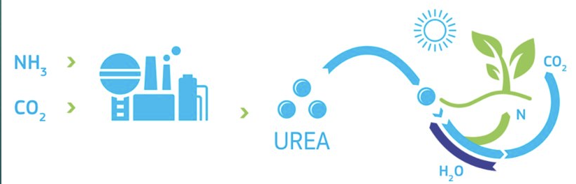
This project explores the feasibility of the electrochemical synthesis of NH3 on a large scale for the purpose of Urea production, which has been gaining attention in today’s increasing market for electricity. The major goal in producing Ammonia through this method is to minimize material and energy consumption, since the Haber-Bosch process uses 2% of the world’s electricity.
Meet our team members

Muhammad Hassan Furrukh
Chemical Engineer
Aspiring Chemical Engineer who is motivated to work in the Oil and Gas industry. Worked as a Pipeline Integrity Engineer at Stantec for his Co-Op.

Pablo Contreras
Chemical Engineer
Ambitious chemical engineer interested in process design and optimization. Currently interning at Suncor in Forthills.

Sanjay Srinivasan
Chemical Engineer with Energy Specialization
Final year chemical engineering students pursuing a master’s degree in Fall 2020. Previously a chemical engineering intern at Nutrien.

Shermarke Yusuf
Chemical Engineer
An enthusiastic prospective chemical engineer with an interest in environmental engineering and sustainable design. Previous work experience as an Environmental Analyst at Suncor Energy.

Syed Ammar Hyder
Chemical Engineer with Energy Specialization
Final year chemical engineering student looking to pursue the development of sustainable technologies. Previously a Research Associate at CERI and Pipeline Integrity intern at TC Energy.
Project Overview
Process Overview
In the Haber process, Hydrogen is used to produce Ammonia and in our electrochemical process, Water is used. In addition, our electrochemical reactor operates at 20 oC and 1 atm, while the reactor in the Haber process operates at 400oC and 250 atm.

Nitrogen and water are passed into the reactor to form Ammonia. The process stream is sent to a condenser that liquefies Ammonia and separates it from the unreacted components. Part of the pure Ammonia leaving the condenser is sold to the market and the rest is sent to the Urea plant. Here, the Ammonia reacts with a fresh feed of Carbon Dioxide to produce Urea at 170oC and 240 atm. The product stream is sent to a separator to extract Urea and water. This stream is then sent to an evaporator to vaporize water and get pure Urea. Hydrogen and Nitrogen leaving the Ammonia reactor is to be separated.
Process Design
Electrochemical Reactor
The reaction of nitrogen gas and water is done in a Membrane Electrode Assembly (MEA) reactor (see Figure below). In this reactor, water is fed to the anode side of the reactor, where water oxidation occurs; and nitrogen gas is fed to the cathode side of the reactor, where nitrogen reduction occurs. The anode, cathode, and membrane used in the reactor are Rubidium Oxide, Amorphous Au/CeOx -RGO, and Nafion 211, respectively . Below are the anode, cathode, and the overall reactions of ammonia synthesis :
Overall: 2N2 + 6H2O → 4NH3 + 3O2 At 20oC ∆Hrxn = +1530.2 kJ/mol
Anode: 6H2O → 3O2 + 12H+ +e
Cathode: 2N2 + 12H+ + 12e– → 4NH3
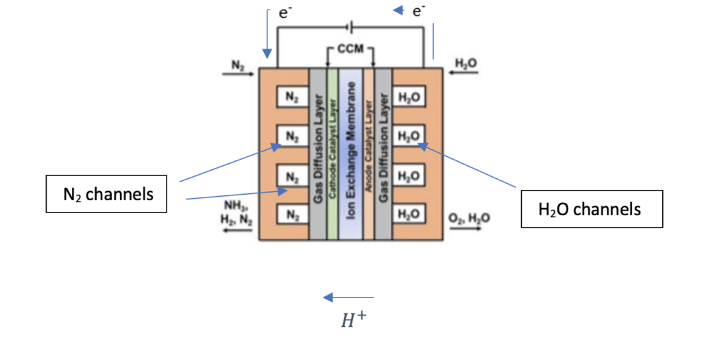
In the figure above, both nitrogen and water enter in the channels of the reactor (flow is into the page). In the anode, water decomposes into protons, electrons, and oxygen. The protons formed at the anode diffuse through a proton exchange membrane (Nafion 211) to the cathode side of the reactor, where protons react with nitrogen to form ammonia. The electrons flow through an external wire as labelled in above figure to the cathode, where it must react simultaneously with nitrogen and the protons that diffused through the membrane to form ammonia. However, in addition to this reaction, the following side reaction can also occur:
Cathode: 2H+ + 2e → H2
Overall side reaction: 6H2O → 6H2 + 3O2 At 20oC, ∆Hrxn= + 1714.92 kJ/mol
For this system, we assumed a single pass conversion of 60% in the ammonia reactor. A Faradaic efficiency of 10% is observed (5). The Faradaic efficiency indicates how much of the total current goes toward making Ammonia. Of the 60% of total nitrogen feed that reacts, only 10% of the nitrogen reacts to form ammonia, while the rest of the 90% is gone towards producing hydrogen.
Urea Reactor
Urea synthesis follows the Bosch-Mieser process, a two-step process that occurs in the Urea reactor. The overall conversion of NH3 and CO2 to Urea is exothermic (ΔHr = -101.5 kJ/mol).
2NH3 + CO2 ↔ NH4COONH2; (ΔH= -117kJ/mol at 130-250 Bar and 160°C) (1)
NH4COONH2 ↔ NH2CONH2 + H2O; (ΔH= +15.5 kJ/mol at 160-180°C) (2)
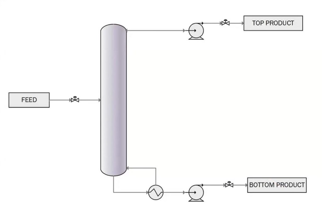
Our process follows the Stamicarbon Urea synthesis process. The reaction heat from the first step drives the reaction. According to Le Chatelier’s principle, high temperatures and low pressures favor reaction 2 but have an adverse effect on reaction 1. So, a compromise is met for process where the negative effect of high temperature on reaction 1 is compensated for by operating the reactor at high pressure, which favors reaction 1. Reactor is operated at 191°C and pressure is 132 atm. Typical urea reactor has a volume of 140m3, with a diameter of 2.5 m and a height of 28.5 m. The overall reaction to form urea is quite slow and has a residence time in the reactor is around 30-40 minutes. The bulk of this residence time is for reaction 2 to occur.
Liquid NH3 is pressurized from 1.01 to 241.01 bar using an isothermal pump, and the liquid NH3 is maintained at -40°C, the flow through the pump is around 1200 kg/h. The CO2 gas at 1.5 bar and 40°C is adiabatically compressed to a pressure of 160 Bar, raising gas temperature. NH3 and CO2 are then fed into the urea reactor which achieves 60% conversion of CO2 to urea. A recycle from the separators is condensed and pumped back into the reactor, which consists of unreacted ammonium carbamate. CO2 and NH3 is fed back to reactor. This process aims to eventually have the overall conversion of CO2 to urea at 100%, and results in the following side reaction:
2NH2COOH2 ↔ H2NCONHCONH2+ NH3 (3)
Cryogenic Distillation
A stream of H2 and N2 leaving the NH3 reactor is to be separated for two main reasons:
- The first of these is product purity. If the H2 is not extracted from our system, it will continue to build up thus negatively impacting the purity of the N2 recycle and consequently, the NH3 product as well. Given our ambitious targets of competing with large-scale Haber plants, a high standard of quality is vital to ensure a customer base for our product.
- Secondly, purified Nitrogen can be obtained from the exit stream of the separator, which may be recycled into the Ammonia reactor, thus allowing for a reduction in feedstock costs.
The stream contains 40.78 kmol/h N2, and overwhelmingly 1651.42 kmol/h of H2. Given that the composition of Nitrogen is now only about 2.4%, due to the Hydrogen-selective nature of polymer membranes, this technology was no longer viable. Therefore, cryogenic distillation, although very energy intensive, was determined to be a more viable technology to use.
Priller & Nozzle
To ease the calculations, we opted to divide the Prilling tower into 3 zones and pick and solve a defining force in each zone.
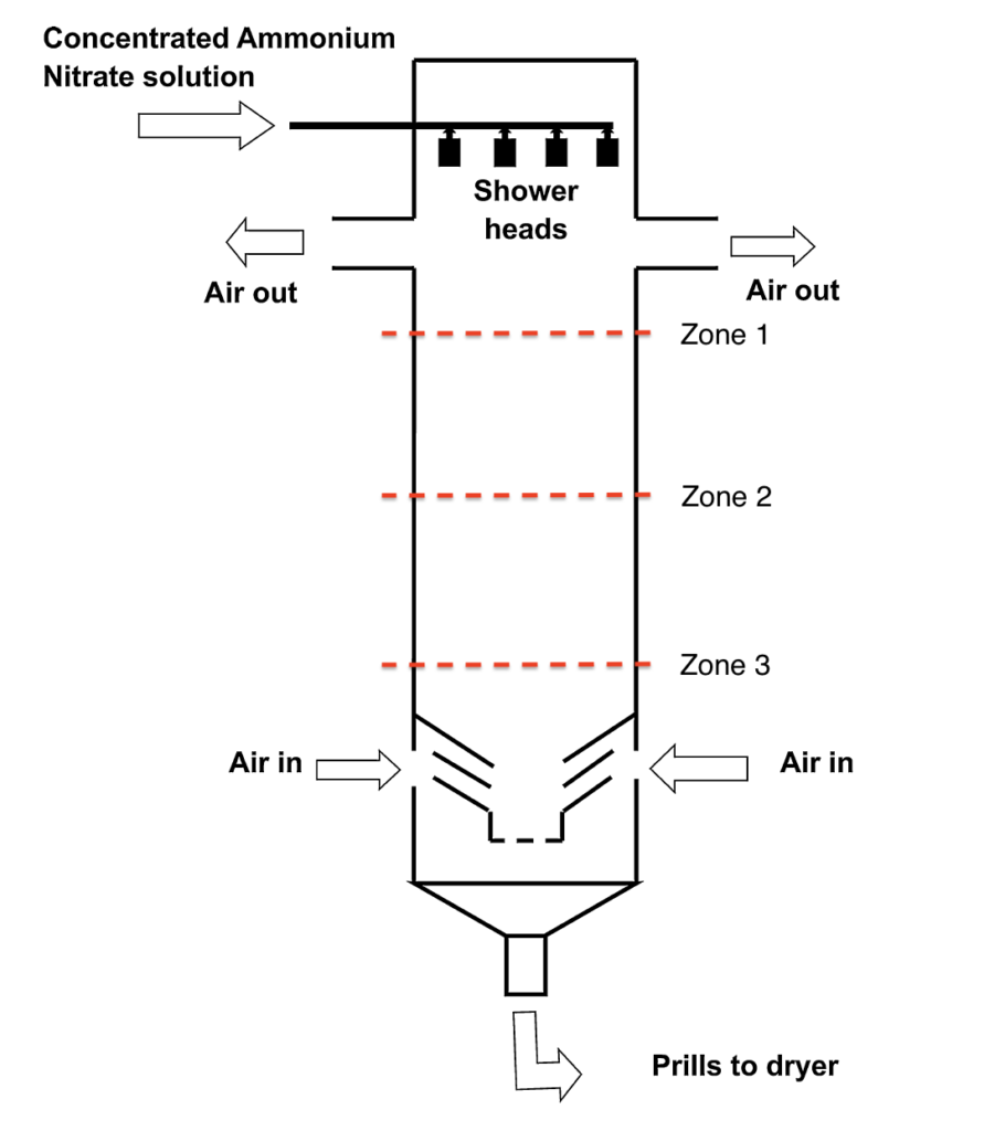
ZONE 1
Sensible heat of the droplet is transferred to the surrounding air; hence it is cooled to a temperature close to the crystallization temperature.
ZONE 2
The solidification of the drop starts. In this zone, the latent heat of crystallization is transferred to the cooling air, and a droplet is totally converted to a solid prill. I
ZONE 3
In the last zone, the prill is further cooled to a lower temperature and loses its sensible heats to the cooling air as it falls down its path.
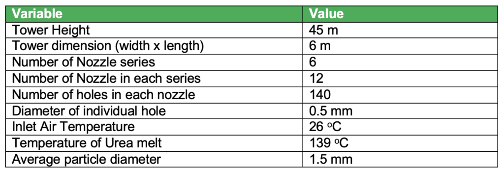
The design parameters are as follows:
Plant Location
Based on the Ammonia production from the existing plants in the area and given the novel nature of the proposed process, it is reasonable to consider the Sherritt International plant in Fort Saskatchewan since it is in conjunction to the Shell Quest Carbon Capture operation.
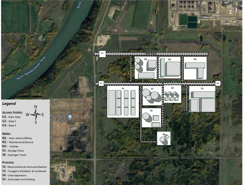
Ultimately, we believe that partaking in the Quest Carbon Capture Project with Shell would be beneficial due to the positive environmental implications and plentiful supply of CO2. Further, the relatively low cost of land means that locating our plant in Fort Saskatchewan is the most ideal route.
Economics
From CapCost, the following data was extracted. The depreciation model used was Modified Accelerated Cost Recovery System (MACRS) over a 5-year period. The project life was estimated over a 10-year period after construction.
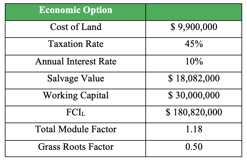
Using this, we can finally attain a Net Present Value (NPV) and a Payback period that is feasible. The NPV at inception is $-71.3 million and in 12 years, will reach an all-time high of $76.7 million. According to CapCost, our construction period is 2 years, with the capital investment split 60% in the first year and 40% in the second year.
Now, the issues with these calculations are that the initial investment for the electrochemical reactor is $24 billion dollars. A reason for the costs being so high is that traditional catalysts used in the electrochemical synthesis of ammonia have very low faradaic efficiencies and cannot be easily scaled up to an industrial setting, so we have had to look at much more costly alternatives, which do have more feasible faradaic efficiencies; however, they are costed far too highly to be viable in a plant setting, however we have no alternatives to be used. The catalysts used for the electrochemical reactor were gold, rubidium oxide and reduced graphene (each having a per gram cost of 60.58 $/gram, 87.80 $/gram and 97 $/gram respectively).
Even without it, we have to price our urea at 13 times the market value, at 6$/kg, to show any positive signs in our economic analysis.

This is a troubling sign for our project, as the economics show that the process is not viable and ready for market. Drastic changes will need to be made in either the reactor design or the production volumes of urea, to show any signs of promise.
Environmental Considerations
Electrochemical synthesis of ammonia produces by-products which are Oxygen and Hydrogen. Hydrogen can be recycled back into our electrochemical reactor to produce protons. Oxygen produced from the electrochemical cell has no use in any of our processes, so it is stored away at high pressure (200 bar) in oxygen tanks and sold to industries for $125/tank. The by-products of urea production are water and Biuret:
- Water is recycled to the electrochemical reactor.
- Biuret production is suppressed by operating the urea reactor with an excess of ammonia.
When looking at the Carbon footprint of urea production, a cradle-to-factory-gate assessment is used. One kg of urea releases around 0.73 kg of CO2; however, its overall carbon footprint from a full-lifecycle assessment is estimated to be around 5.15 kg CO2-equivalent (this value includes GHG emissions from Haber-Bosch process). The primary issues stem from the energy used in production and transportation, and emissions of nitrous oxide (N2O). N2O is 300 times more potent than CO2 and its emissions represent approximately 6% of the global anthropogenic greenhouse gas source. If we neglect the GHG emissions from the Haber-Bosch process (which produced 1.33 kg CO2e), we get a carbon footprint of 3.82 kg CO2e/ kg Urea produced. While this value is closer to our true carbon footprint, it is also not fully accurate as this calculation considers that no GHG’s are produced in the production of Ammonia from electrolysis, which is untrue.
Acknowledgments
We would like to thank Dr. Karan, our project supervisor, for providing us with expert advice throughout the entire project. Secondly, we would like to acknowledge Dr. Michael Foley, course instructor and Dr. Hector de la Hoz Siegler, course coordinator for providing us with all the necessary guidance.
