Project Category: Chemical

Join our presentation
About our project
Liquefied natural gas (LNG) is natural gas in its liquid form reduced to 1/600th of its volume through a liquefaction process. LNG is a safe and feasible method of transporting natural gas to remote locations and international markets without direct pipeline access. Once LNG reaches its final destination, it can be regasified for heating and power generation.
With an increasing demand in lower emission power generation alternatives, LNG has become an attractive fuel due to the fact that its combustion produces less greenhouse gas emissions than conventional coal and oil. Currently, the majority of natural gas is transported with pipelines. However, the construction of pipelines has been surrounded with political turmoil and decreased interest. Liquefying natural gas reduces the need for pipeline transportation of natural gas by transporting LNG in iso tanks.
Future Fuel Consulting Ltd. has designed a plant that will convert 60 MMSCFD of natural gas into LNG by examining several design alternatives and completing an economic analysis. The plant will be located in Northern BC with the feed natural gas meeting TC Energy pipeline specifications.
Meet our team members

Details about our design
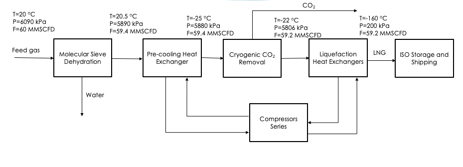
PROCESS OVERVIEW
The process begins with water in the feed natural gas being removed using molecular sieve dehydration to prevent hydrates from forming when cooled to low temperatures. This process uses temperature swing adsorption to reduce the water content to less than 0.1 ppmv.
Next, the dry gas enters a pre-cooling heat exchanger and is cooled using mixed refrigerant to -25oC.
After pre-cooling, the gas enters the cryogenic carbon dioxide removal process where CO2 is removed from the stream using pressure swing adsorption. The regeneration of the adsorption columns will yield a high purity CO2 stream which can be sold as a product for EOR applications.
After CO2 removal, the stream enters two liquefaction coil wound heat exchangers in series in order to cool and liquefy the gas using the refrigeration cycle. The product exiting the final heat exchanger will be fully liquefied and enters an expansion valve to set the pressure to correct specifications. This is then the final product which can be sent to iso storage tanks for shipping.
The primary parts of the process that were designed in detail include the temperature swing adsorption of water and cryogenic carbon dioxide removal. The equipment used in these processes were sized according to industry standards, and the adsorption of each component was modelled using isotherm data.
HOW OUR DESIGN ADDRESSES PRACTICAL ISSUES
Cleaner Burning Fuel
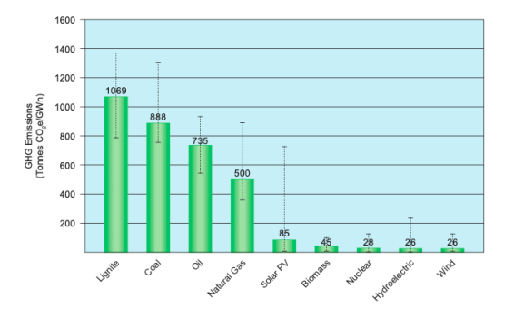
Natural gas demand is increasing due to increased interest in cleaner burning energy sources to reduce global greenhouse gas emissions. Natural gas burns less CO2 emissions than coal and oil, so LNG can be accepted as an alternative fuel source for power generation.
High Market Demand
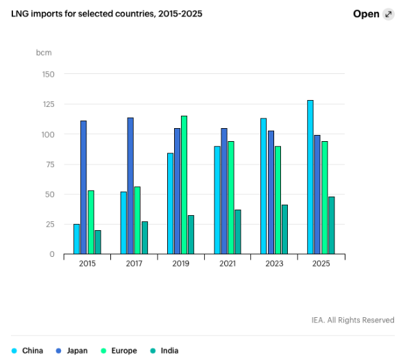
This project can transport LNG in iso-tanks by rail to many remote communities in Canada without pipeline access to natural gas. LNG has also attracted international markets in Asia, so the product can safely be shipped overseas. Global trade of LNG is expected to increase by 21% from 2019 to 2025 (2).
WHAT MAKES OUR DESIGN INNOVATIVE
The conventional LNG plant design uses an amine separation process to remove carbon dioxide which is very resource intensive and uses carcinogenic absorbents. In the traditional process, the feed gas is heated to remove carbon dioxide during amine separation which is then cooled for liquefaction.
Our design uses cryogenic CO2 removal with pressure swing adsorption, which is much less energy intensive and eliminates the need for hazardous substances. In our process, CO2 is removed after precooling, which reduces energy consumption due to the fact that heating is not required for pressure swing adsorption.
WHAT MAKES OUR DESIGN SOLUTION EFFECTIVE
LNG can safely transport natural gas in iso tanks due to its reduced volume. Our process reaches complete liquefaction of natural gas by cooling to -160oC, making this possible.
The amine separation process used in the traditional LNG plant requires the purchase of absorbents including DEA and DGA. Since we are not using the amine process, purchasing several absorbents is not required and instead only requires desiccant used for pressure swing adsorption.
HOW WE VALIDATED OUR DESIGN SOLUTION
Molecular Sieve Dehydration
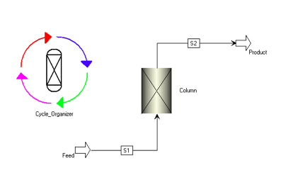
The removal of water through temperature swing adsorption was modelled using Aspen Adsorption. By using this software, the adsorption was validated by examining the amount of each component adsorbed by the molecular sieves. The simulation resulted in water being completely adsorbed with negligible amounts in the outlet stream. By having negligible water in the outlet stream, it can be ensured that no hydrates will form when the gas is cooled to cryogenic temperatures.
To complete this simulation, Toth isotherm properties for molecular sieve of the 4A type were used to examine the selectivity and determine the amount of water adsorbed in the column. It was concluded that the water content reduced from 300 ppm to 1.19×10⁻⁹ ppm.
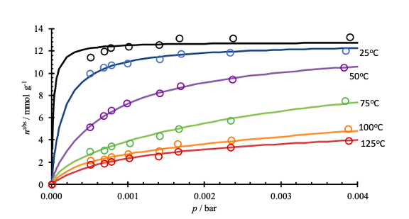
Cryogenic CO2 Removal
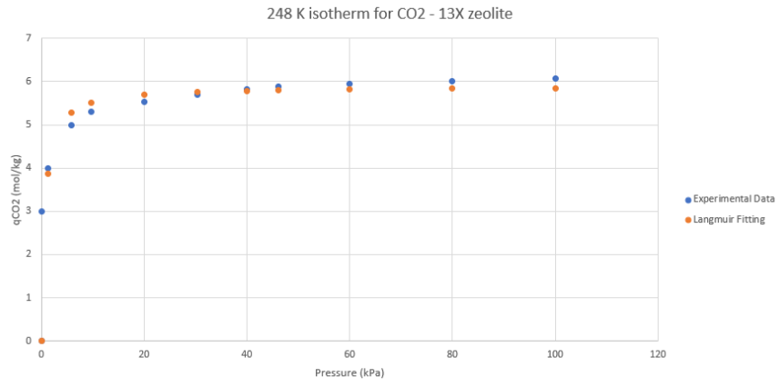
The removal of CO2 using pressure swing adsorption at cryogenic conditions was modelled using a fitted Langmuir isotherm for 13X molecular sieve. The properties of this isotherm were used to calculate the amount of each component adsorbed and the mass of adsorbent required to completely remove the carbon dioxide. The CO2 removed from the gas can be sold as a product for enhanced oil recovery applications.
Based on calculations using the isotherm below, the content of CO2 in the gas stream was reduced to 50 ppm.
FEASIBILITY OF OUR DESIGN SOLUTION
Optimization
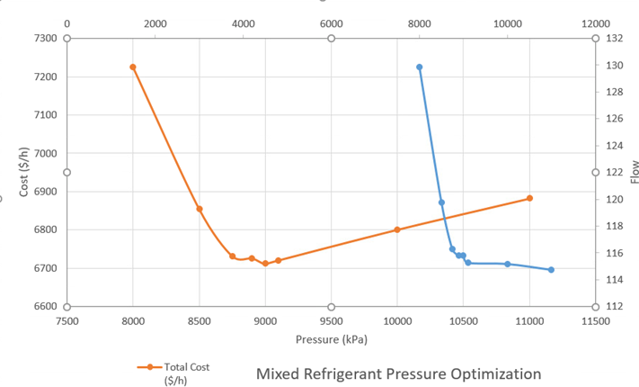
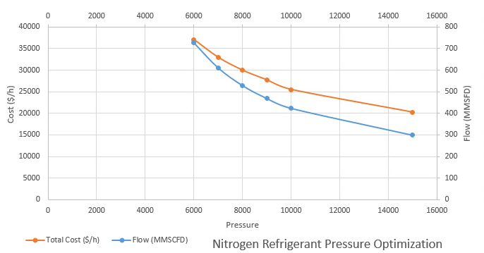
Optimization was completed on the refrigeration cycles to determine the best pressure and flow rate to help decrease costs. Based on the optimization, the utility costs decreased by 40%.
Optimization was performed on the mixed refrigerant cycle to identify the optimal refrigerant pressure, composition, and flow rate.
In addition, optimization was completed on the nitrogen refrigeration cycle to identify the optimal pressure and flow rate.
Safety
Safety was a priority when designing this plant. Instrumentation and controls will be implemented to monitor variances in temperature and pressure. A HAZOP was conducted on one of the adsorption beds in the temperature swing adsorption process to assess hazards and ensure proper designs were implemented to reduce and eliminate risks.
Results
The design concluded an LNG production rate of 3840 m3/day and CO2 production rate of 65.26 m3/day which can both be sold as products.
The total capital investment was calculated as $600,000,000. Based on the complete economic analysis, the breakeven price of LNG is $15.4/mmBtu in order to be profitable. This is based on the product being sold to remote communities and locations with high need for natural gas in Canada.
REFERENCES
- McIntyre, J.; Berg, B.; Seto, H.; Borchardt, S. Comparison of Lifecycle Greenhouse Gas Emissions of Various Electricity Generation Sources. World Nuclear Association. http://www.world-nuclear.org/uploadedFiles/org/WNA/Publications/Working_Group_Reports/comparison_of_lifecycle.pdf (accessed Apr 8, 2021).
- 2021-2025: Rebound and beyond – Gas 2020 – Analysis. IEA. https://www.iea.org/reports/gas-2020/2021-2025-rebound-and-beyond (accessed Apr 8, 2021).
- Wynnyk, K. G. High-pressure Adsorption Equilibria Aimed at Optimizing Sour Gas Conditioning. University of Calgary. Thesis, 2019.
- Grande, C. A.; Blom, R. Cryogenic Adsorption of Methane and Carbon Dioxide on Zeolites 4A and 13X. Energy & Fuels. 2014, 28 (10), 6688–6693, DOI: 10.1021/ef501814x
Partners and mentors
We want to thank the many people who helped us with this project. Our supervisor Dr. Nashaat Nassar guided us through the project. The technical advice we received from Umar Siddiqui and Awais Salahuddin was very valuable. Dr. Michael Foley and Dr. Hector Siegler provided informative course lectures throughout the year.
Our photo gallery
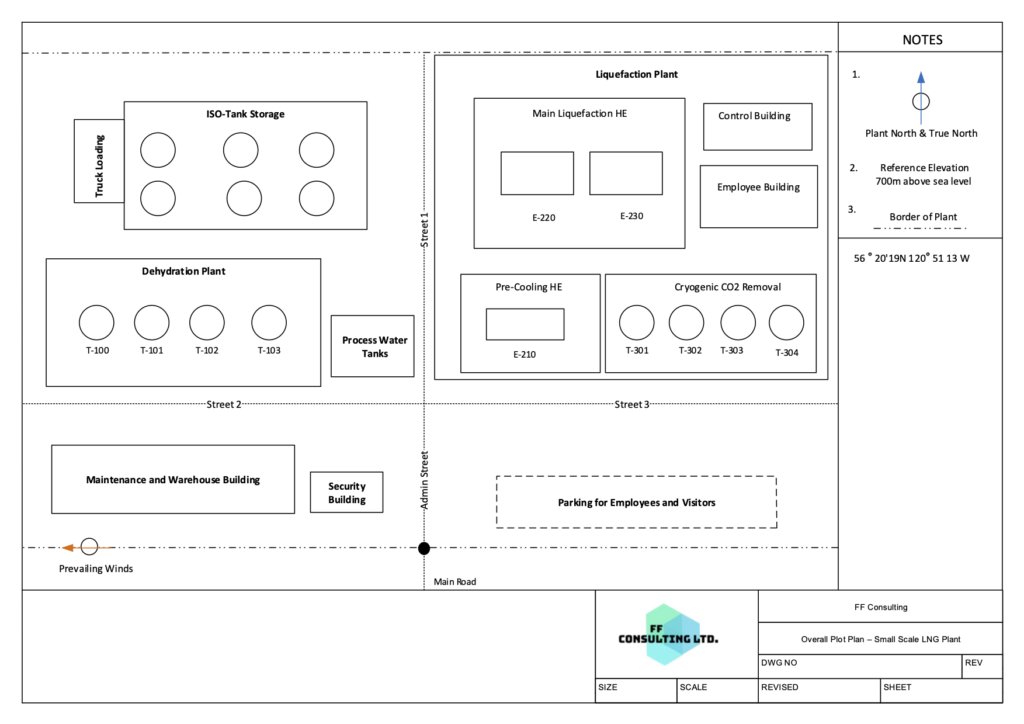
Plot Plan 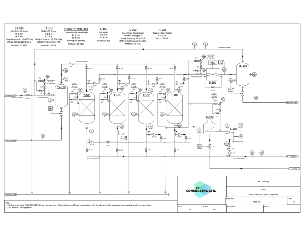
P&ID 1 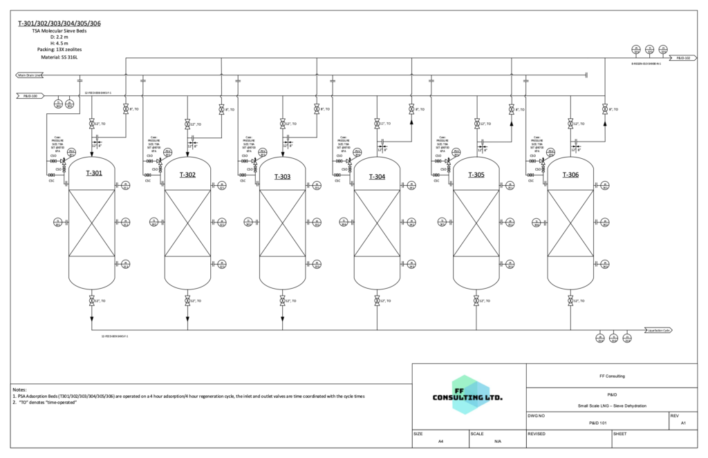
P&ID 2 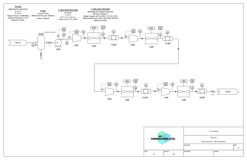
P&ID 3
