Project Category: Chemical

Join Our Zoom Room
About our project
The goal of our project is produce 12500kg/h of molten urea at a 99.2% purity from a feed source of pure carbon dioxide and ammonia. We chose the Sherritt International ammonia plant in particular as our supplier.
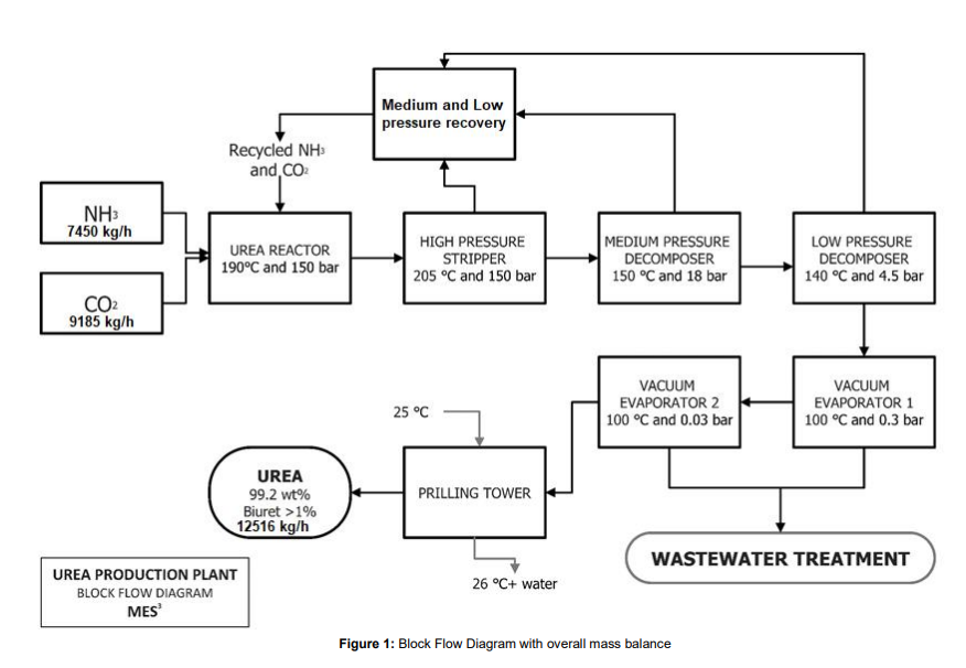
In the urea production process, urea is first synthesized from ammonia and carbon dioxide, at a pressure of 150 bar and at 188°C in the reactor. The stream leaving the reactor contains only 34% urea and the rest is comprised of carbamate, water and ammonia. To obtain 99.2% urea, further purification steps are required. The first is the stripper, which strips unreacted ammonia and CO2, purifying the product stream to 45 wt% urea. The resulting stream then goes into the medium and low pressure decomposers , where due to the sudden decrease in pressure, flash evaporation of the solution takes place and the unreacted ammonia and CO2 in the gas phase is recovered and recycled back into the reactor. The liquid stream coming out of the low pressure decomposer now has a concentrated urea solution of 72%. Then the product stream is sent to the vacuum evaporator, aimed at concentrating the urea solution through evaporation of the remaining water, to give us molten urea of 99.7 % purity, which is then sent to the prilling tower to produce urea prills.
PROJECT MOTIVATION-
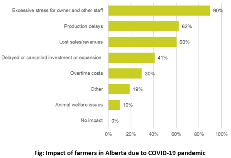
The effects of COVID-19 have been felt in almost every sector, and agriculture is no different. Border closures and travel restrictions made it very difficult for employers to bring in temporary foreign workers, which is a vital source of labour in many agriculture industries. Social distancing requirements and travel restrictions have prevented farmers from sowing their crops, leading to labor disruption, and wreaking havoc on supply chains. As a result, there has been a 6 % rise in food prices across Canada and a decline in the household incomes of smallholder farmers, which make up about 45% of Alberta’s population. In addition, labour shortages attributed to COVID-19 also resulted in production delays for 62% farmers and lost sales for 60% farmers.
Unprecedented crises calls for unprecedented measures.
OUR SOLUTION
Setting up a urea production plant can help these farmers make up for the lost income as urea has the highest nitrogen content of all fertilizers, and it thus provides a cheap source of nitrogen to promote agricultural growth and animal feed. With 86% of Canada’s farming happening in the Prairie Provinces, urea demand in the location is increasing day by day.
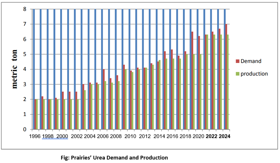
The graph of last 20 years of urea demand and production shows that Alberta has been lagging demand not only during COVID but forever. The demand is increasing very rapidly due to high population concentration and agriculture dependence. It is expected that in 2024, demand of urea in Prairies will reach some 9 million MT and installed capacity will remain only 6.9 million MT. So, a huge demand is there for new capacity installing. In addition, the unemployment rate in Alberta is at an all-time high: at 11.1 % as of November 2021 and is predicted to go as high as 15.5 % in May 2022. These high numbers are in-part due to the on-going COVID-19 pandemic. Therefore, the opportunities and job openings initiated by the urea production plant would not only help the farmers but could also be promising in the current economic climate.
Meet our team members

” I am a fifth year chemical engineering student. A great man once told me “If you ain’t first you’re last”. I try to live my life to that quote.”

“4th year chemical engineering student at the
University of Calgary. Completed a summer research position under Dr. Jinguang
Hu at the university where the focus was on photocatalysis of biomass.
Passionate about the oil & gas, polymer, and biochemical industry. Hobbies
include doing fun activities outdoors especially during the summer.”

Shazia Shareef

Sunjit Singh

“I’m a fourth year chemical engineering student. I’ve worked in a few group projects over the past couple of years and like to collaborate with others. I have an interest in a few career sectors, some of them being environmental studies, sustainable development, and safety and risk management.”
Details about our design
Process Overview
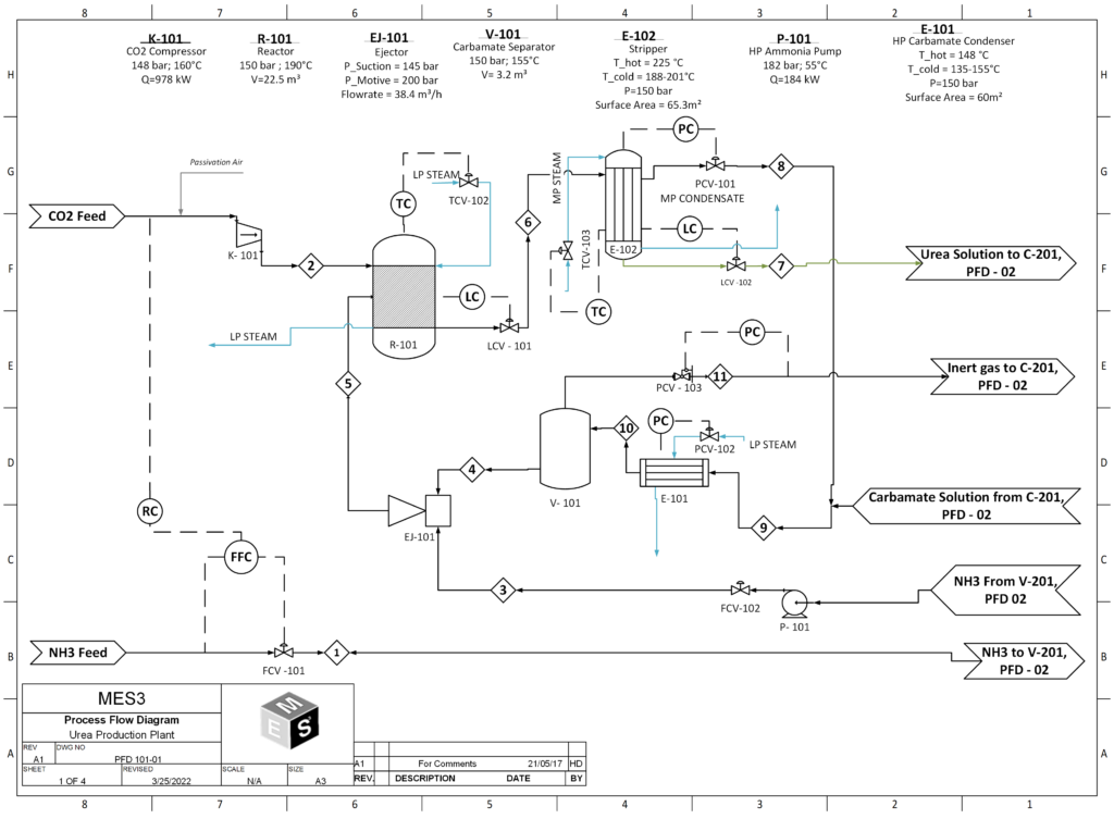
- Reactor:
The reactor is operated at 190 °C and 150 bar. NH3:CO2 molar feed ratio to the reactor is 4:1. One pass conversion rate of CO2 to urea is about 68%. Following reactions occurs inside the reactor.
2NH3 + CO2 ↔ NH2COONH4 + heat ∆H = +15.5 kJ/mol
NH2COONH4 + heat ↔ NH2CONH2 + H2O ∆H = -117 kJ/mol
Where
NH3 = ammonia
NH2COONH4 = ammonium carbamate
NH2CONH2 = urea
- Stripper:
The stream leaving the reactor contains 34 wt% urea and the rest comprises ammonium carbamate, water and ammonia. To obtain a product that meets purity specifications, further purification steps are needed, the first of these is the stripper. The stripper is a falling film heat exchanger which facilitates the decomposition of ammonium carbamate into ammonia and CO2. These gasses help strip additional ammonia from the liquid thereby purifying the product stream to the point where it contains 42 wt% urea. The urea solution coming from the stripper makes its way to the medium pressure decomposer.
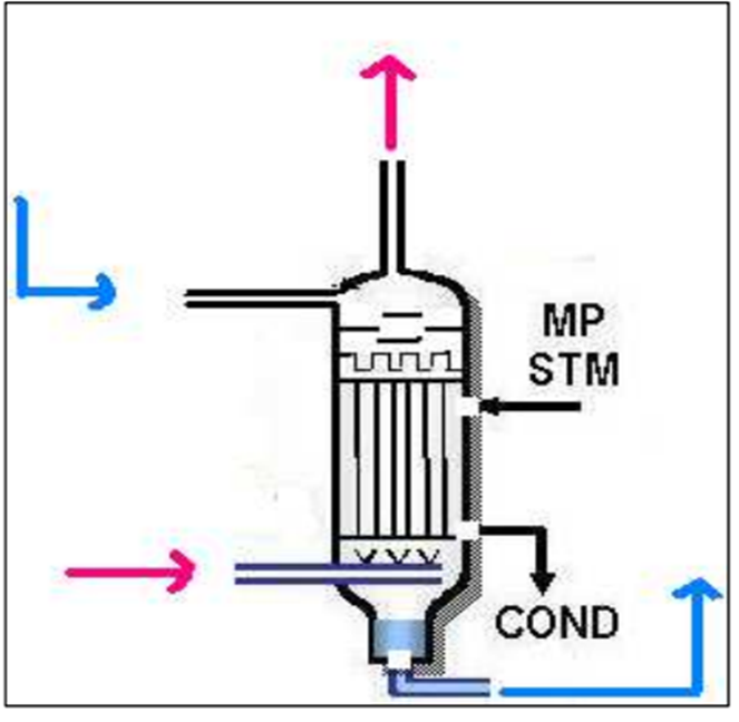
Fig: Diagram of a stripper
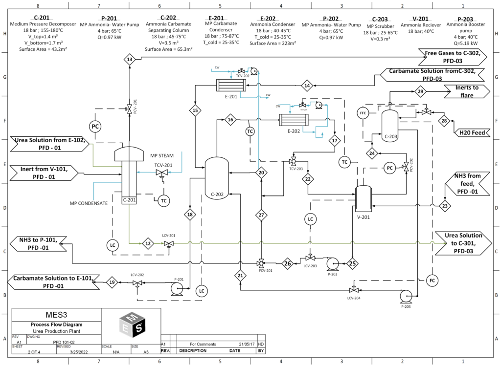
- Medium-Pressure and Low-Pressure Decomposers
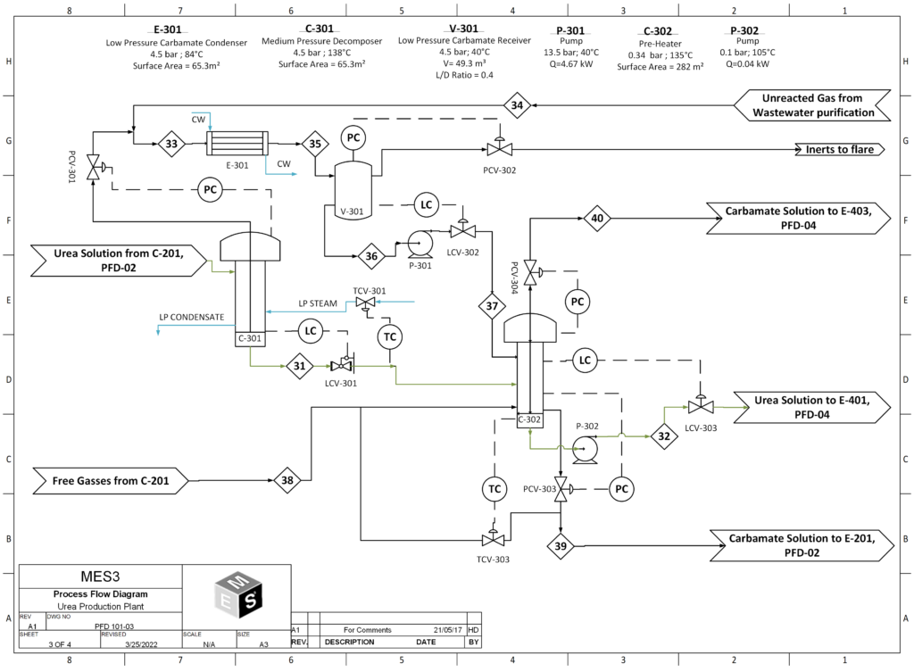
The medium pressure decomposer, operating at 18 bar purifies the urea solution to 62 wt% urea. The purified urea liquor then makes its way to the low-pressure decomposer, operating at 4.5 bar where the resulting urea solution is further purified to 72 wt%. All ammonia and ammonium carbamate are removed by the Decomposers before it is transferred to the vacuum evaporation section.
Fig: Diagram of a Decomposer
- Vacuum Evaporator:
The vacuum evaporators concentrate the urea solution through evaporation of any remaining water. The preceding steps (namely, stripper and decomposers) sufficiently reduce the ammonia and ammonium carbamate content, making water the biggest contamination of the product. The urea liquor is transported into the first vacuum evaporator through a heating element. The lower pressure of 0.3 bar will ensure that enough water evaporates to increase the purity to 96 wt% urea. The urea solution from the first vacuum evaporator then goes into the subsequent vacuum evaporator. The last evaporation step consists of a similar setup, with a vacuum evaporator and a heating exchanger; only the pressure is even lower (0.03 bar) in order to evaporate the last remnants of water and increase the purity of the urea up to 99 wt%. The evaporated water is brought to atmospheric conditions and condensed in two heat exchangers before it is sent to the wastewater treatment section.
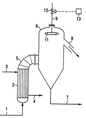
Fig: Vacuum Evaporator
WHAT MAKES OUR DESIGN INNOVATIVE
To determine the most appropriate technology, each of the 3 processes we looked at (StamiCarbon, Once Through, and SnamProgetti) were compared using the Kepner-Tregoe (KT) Decision Analysis technique. This system ranks a series of chosen criteria by allocating weight points with higher values being the most advantageous, and then by taking the highest summed score as the most favorable design. Upon completion, it was seen that SnamProgetti scored the highest overall. This was considered to be the best process out of the three because of the high urea yield in the final product, less toxic emissions, and amount of operational information available.
WHAT MAKES OUR DESIGN SOLUTION EFFECTIVE
Some of the key changes we performed to the SnamProgetti design were:
- ) Replacing reactor from a PFR to a CSTR design. This design change was implemented to improve controllability and mixing due to the fact that this reactor is well mixed. It also eliminates the need for the plug flow assumption validity therefore the need to further verify the axial dispersion is minimal. Also heat integration calculations were performed by designing a heat exchanger for the reactor. The heat exchanger was designed as a shell and tube heat exchanger and used water at 25°C as the service fluid. The implementation of the heat exchanger will help to reduce the costs associated with the utilities of this unit.
- ) The decomposers were designed as a vertical separator as a decomposer unit is both a Separator and heat exchanger. Calculations were done for both designing the decomposers as either heat exchangers or separators and after review the calculations it was decided that designing them as separators was the safest route to take as the area and volume calculated was larger this way. The choice of a vertical separator was picked over that of a horizontal separator since yes the initial investment may be higher however, the utility, upkeep, and safety of them is greater than there counterpart.
- ) The vacuum evaporator design was altered from 2 independent evaporators to a 2 effect evaporation system. This in turn will reduce the amount overall steam required and reduce the utilities costs associated. It will do this by using using a heat source for the first effect and then using the vapors from the first effect as a heat source for the second effect.
- ) For the condenser the outer diameter was changed from 30mm to 20mm while keeping the internal diameter constant and reducing the baffle spacing. This in turn will reduce the overall area of the condenser and in turn reduce the amount of cooling water needed.
- ) The addition of three scrubbers in the vacuum section will help decrease the amount of urea in the stream going to the wastewater. This will lead to less steam being needed to purify the wastewater stream. Therefore decreasing the utility costs associated with this process.
- ) The last solution that makes our design effective is installing three condensers in the vacuum section as well. This will lead to another decrease in steam required for the wastewater effluent. Once again further decreasing the utility costs associated with wastewater effluent.
HOW WE VALIDATED OUR DESIGN SOLUTION
Symmetry software was used to validate these changes for each process and the entire design. Hand calculation were done as well to help validate the data obtained. Also the use of reliable papers were used to help guide, make assumptions and validate these changes performed.
FEASIBILITY OF OUR DESIGN SOLUTION
While around 80-85% of urea produced is used as a fertilizer, it has other uses, which include the manufacture of the melamine, used in melamine-methanol resins. However, a staggering 40% of all food grown in the world is fertilized using urea. Worldwide, there were 218.21 million tons of Urea produced in 2019. Based on a survey done between 2018-2019, the amount of urea produced globally increased from 210 million metric tons to 218.12 million metric tons. 15 It’s estimated that by 2030, the production of urea will increase a considerable amount to 300 million metric tons. The top 5 producers were China, India, Russia, Indonesia, and Pakistan. The global market cap of Urea was 40.55 billion USD and is expected to reach 49.67 billion USD by the year 2027. It is also expected to have a compound annual growth rate of 2.8%.
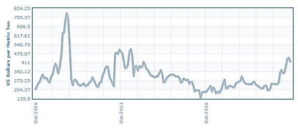
The above figure which tracks the price per ton of urea since 2006 to present day shows urea is starting to get back to some of the highs it hasn’t seen since 2011/2012 this is good news for our plant as it will increase the economic feasibility of succeeding. Also since COVID-19 the demand of urea has began to skyrocket, which once again only adds to the feasibility of this design and project.
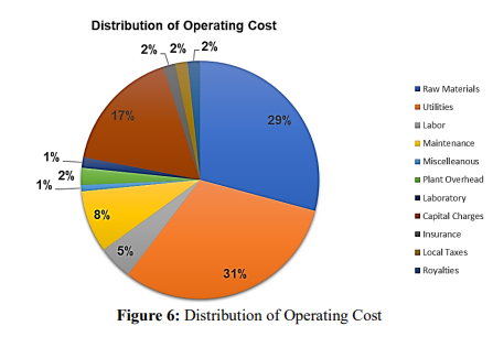
Another critically important part of the feasibility of this design is the pie chart above both the raw material and utilities costs will take up a combined 60% of our projects operating costs. Therefore the going price of ammonia, carbon dioxide, and electricity can affect how profitable this operation will be going forward.
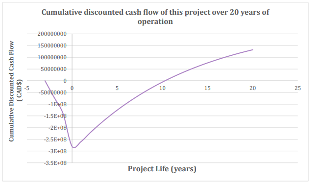
It was determined from DCF that this project will have a net payout time (NPT) of 10 years and a positive net present value (NPV) of CAD$ 132 million after 20 years of operation. The internal rate of return (IRR) for this project is at 21.0%. This is very good news for our design as this shows that the economic feasibility for success is there.
Partners and mentors
We would like to thank our supervisor, Dr. Maen Husein, as well as the course coordinator Dr. Hector de la Hoz Siegler, for both of there dedication and patience on our consulting firm’s work throughout these past eight months.
Our photo gallery