Project Category: Civil
Join our presentation
To learn more about our project, feel free to join us in our ZOOM Room on April 5, 2022 from 10:00 am – 12:30 pm MDT.
Passcode: 340285
Please contact hamza.ejaz@ucalgary.ca if you experience any technical difficulties.
About our project
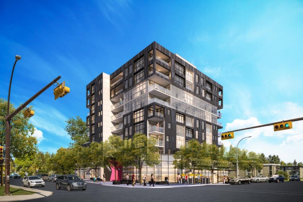
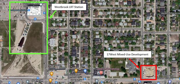
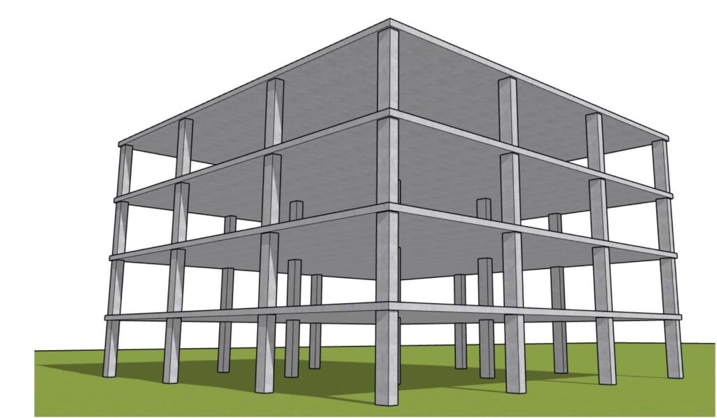
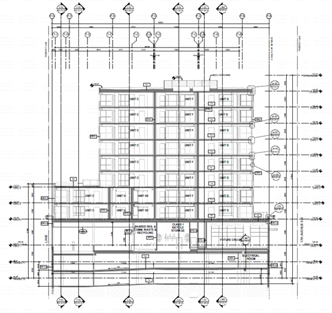
The 17West Mixed-Use Development is located in the inner-city community of Shaganappi, directly across the community border of Killarney. The building is nine stories high, with an upper and lower roof, 101 residential units from floors two to nine, and two underground parkade levels consisting of 89 parking stalls. The commercial retail space on the main floor invites pedestrian traffic and creates an interface between community and commercial. Located at the intersection of 17th Avenue and 29th Street SW, 17West will serve as a community hub for the residents of Killarney and Shaganappi, and is located optimally for transit users.
After conducting conceptual and preliminary analysis on three different structural systems (flat plate slab with shear wall, conventional reinforced concrete slabs with beams and a shear wall, and a composite slab with a steel rigid moment frame), the flat plate slab system was chosen and taken to detailed design. This system was chosen based on the design criteria, in which constructability and material cost ratings were most favorable. The building was designed to efficiently resist all gravity and lateral loads. The roof and floor systems use two-way flat plates with no drop panels, which rests directly on the columns. Columns were designed based on their gravity loading, bending, and location. Shear walls were designed to resist the most critical loading case and are optimally located along the stairwell and elevator shaft. Foundation walls were designed in accordance with the site geotechnical report, and the parking slab rests on conventional strip and spread footings.
Meet our team members


Details about our design
HOW OUR DESIGN ADDRESSES PRACTICAL ISSUES
The practical issues our design must overcome included cost and constructability. As our building is in a major City, we want to ensure that construction is completed efficiently, and public disruption is minimal. Ultimately, we looked at how different structural systems would be constructed in our region and their associated construction timelines, the intended purpose of the building and the system’s suitability, and the budget required. By comparing the total material cost for all three systems, as well as analyzing which system would be the most feasible given the building’s purpose, we determined the flat plate with shear wall system was the best option.
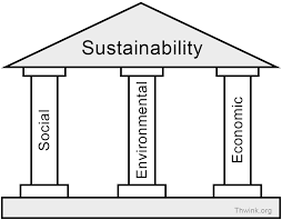
Sustainability was also an important consideration for our design. We considered the three key pillars, and asked ourselves what we could do to positively impact them. We asked ourselves questions such as which material has the lowest lifecycle carbon footprint; what is the timeline for construction for each system, and thus what is the public impact; what design yields the most rentable space to take full advantage of our building’s capacity; and what is the overall impact on the surrounding community? Ultimately, we quantified our analysis by comparing the carbon emissions for material production among all three systems and assessed social and economic impacts qualitatively. We found that while concrete is still far from being eco-friendly, there are ways to reduce the footprint by using local supplementary cementitious materials and chemical admixtures. Our system also utilizes one structural trade. Efficient design was employed to ensure the lowest amount of material was used, while still meeting safety, strength, and durability requirements.
Project risks were also analyzed. As future engineers, it is important we practice risk analysis and devise mitigation strategies for ourselves and for the client. Risks exist in all stages of the project, from preliminary design through to construction. As we are responsible for building design and ensuring all calculations adhere to code and best practices, we focused on evaluating and mitigating risks not under our direct control. Our design was chosen such that local trades have the knowledge and expertise to construct the building, thereby reducing constructability risks.
Based on the criteria discussed, we selected a flat plate slab with a shear wall for our building’s structural system. The elevator shaft/stairwell provides a natural shear wall location, and concrete material has built in fire-proofing and acoustic and vibration resistance. Additionally, using a flat plate system minimizes ceiling obstructions and allows for simple mechanical and electrical system installation. For these reasons, our chosen structural system is best suited to address practical issues.
WHAT MAKES OUR DESIGN INNOVATIVE
Concrete design must adhere to the various standards, procedures, and codes published by governing bodies. As such, design innovation is possible, but limited. Our group collaborated with our industry advisor to gain insight on practices used to reduce material and associated costs, utilize the space, and transfer loads effectively.
The flat plate slab and shear wall system cut project costs as it eliminated beams from the design. This allows for simpler installation of mechanical and electrical systems that need to be routed throughout the floor. Additionally, the built-in fire proofing of the material eliminated the need for fire resistance coatings. We designed our system efficiently, and ensured it met structural requirements with the least amount of material possible. All slabs are 250 mm thick, and column sizes specific to location and loading.
Space utilization was another way we brought innovation to our design. The intended purpose of the building combines residential and commercial, making it cross functional. Lower floor to floor heights associated with our chosen structural system allowed us to maximize the units available while adhering to the building footprint.
Load transfer options were evaluated, and our chosen system has columns running from the upper roof to the lowermost slab. Spread footings were utilized to transfer loads to the ground, and we also designed foundation walls to resist soil pressures.
Our group worked together effectively, and each team member’s unique skillset contributed to the final product. Our team had two project managers – one in the fall semester, and one in the winter. These individuals acted as the liaison between our group and our advisors, but we all took the initiative to work together and execute our project deliverables. Our group consisted of eight members, only three of whom were enrolled in the structural minor. As such, those group members primarily led the design, but also guided other members and provided them with references to aid them in the design process. Some of our group members excelled in artistic and visual elements of the project, and as such those members were utilized for our design drawings and project presentations. Overall, the unique skillset of each member of the team helped to contribute to the final product.
WHAT MAKES OUR DESIGN SOLUTION EFFECTIVE
We chose the flat plate system for the following reasons:
- Lower floor to floor heights (more rentable space with the same building envelope)
- Removes the need for false ceilings
- Simplifies the mechanical and electrical system installation
Our design material is primarily concrete, with steel rebar reinforcement. In addition to its strength, concrete has built-in fire protection, and the material mass provides acoustic resistance, vibration control, and thermal insulation – all of which are appealing qualities for a building with residential units.
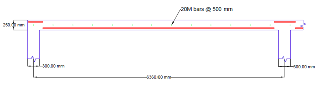
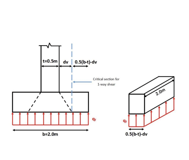
Two way reinforced concrete slabs were designed for all floors based on CSA A23.3 Clause 13.2, which establishes the minimum slab thickness based on the longest clear span in the slab. Calculations were performed on the heaviest loaded floor, which was the main floor commercial sab. This slab was designed to be 250mm thick. All other floor designs were extrapolated from here.
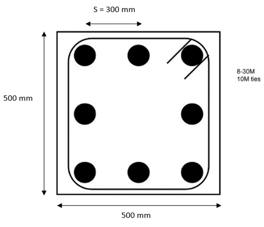
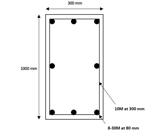
Column design was performed on an interior column and exterior corner column. The interior column chosen was based on its location, tributary area, and gravity loading. Concrete columns can be constructed efficiently and size can be altered easily using forms.
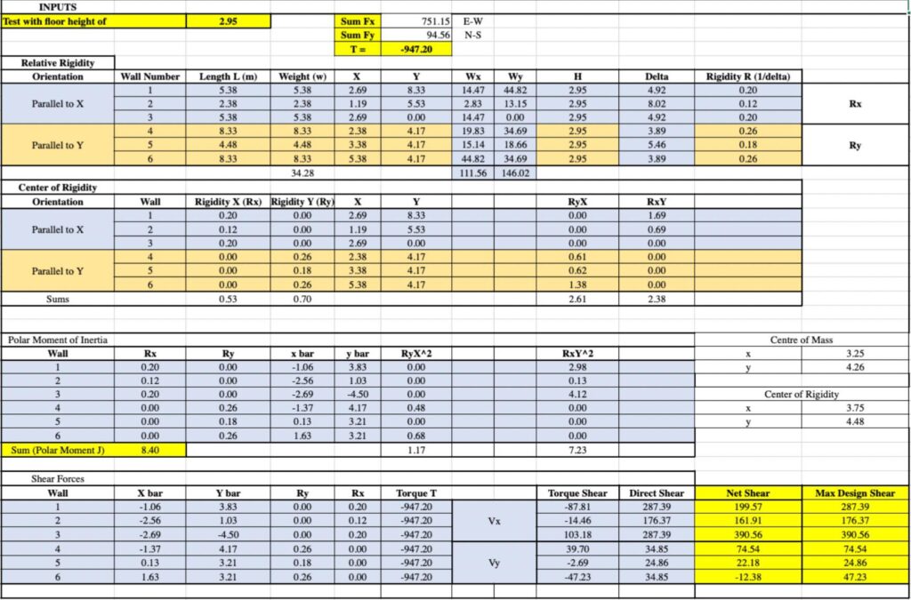
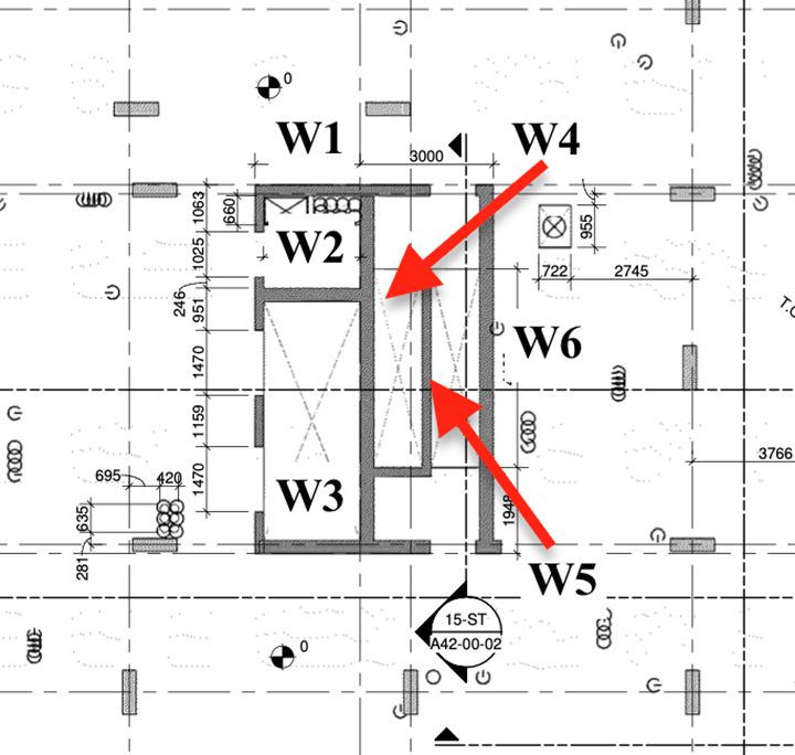
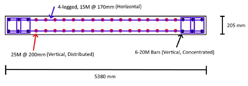
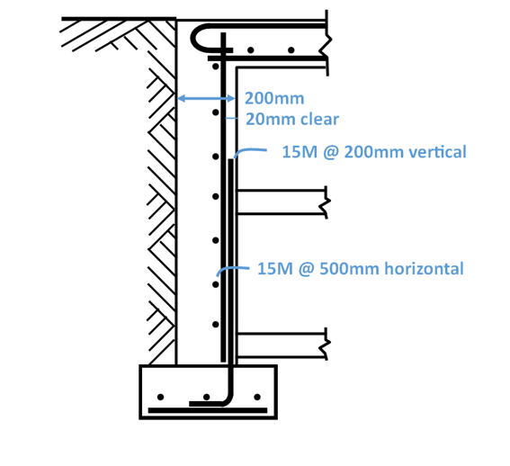
Lateral loads, such as wind and seismic forces, are resisted by the six shear walls that are concentrated in the center of the building. The architectural layout of the building provided a natural location for the shear walls, and they have been designed integrally with the stairwell and elevator shaft. Each wall is responsible for resisting a portion of the shear force experienced on each floor. Calculations were computed in an excel model, giving us the net factored shear force per shear wall. The wall taking the heaviest shear force was designed.
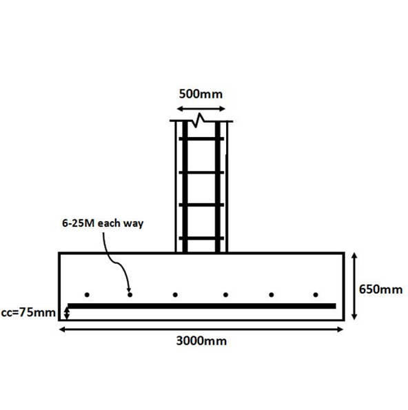
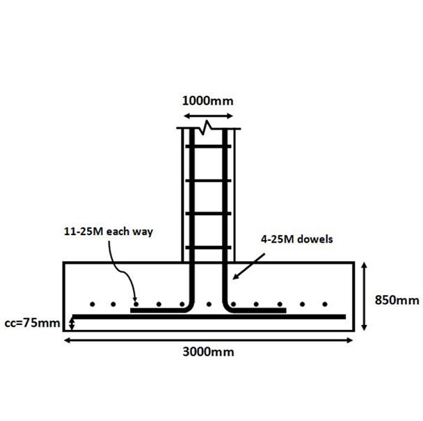
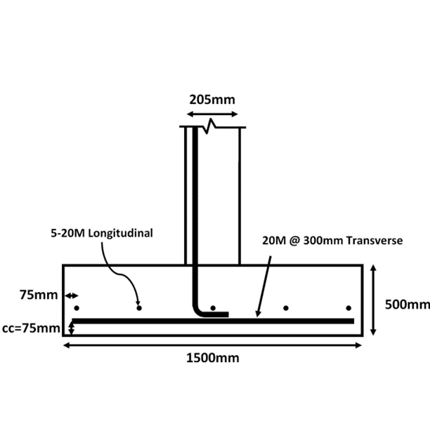
Finally, forces from the shear wall and columns are transferred to the foundation. Spread footings were designed to transfer forces from the columns and strip footings were designed to transfer forces from the shear wall. Footing types were chosen based on recommendations from the geotechnical report.
HOW WE VALIDATED OUR DESIGN SOLUTION
Our project adheres to the following codes and standards:
- National Building Code of Canada, 2010 Edition
- Alberta Building Code, 2019 Edition
- CSA-S413-07 (R2012): Parking Structures
- CSA-A23.1-09: Concrete Materials and Methods of Concrete Construction
- CSA-A23.2-09: Methods of Test and Standard Practices of Concrete
- CSA-A23.3-04 (R2010): Design of Concrete Structures
Because calculations were performed per floor, excel was used to expedite the process. For example, the model used to calculate shear forces in all six shear walls per floor is shown below.
Design calculations were discussed in depth during regular meetings with our advisors for validation and review. The knowledge of our mentors was extremely useful, as they helped us to see the practical side of design that comes with experience in industry.
The team utilized structural knowledge gained from previous courses. Other pertinent documents referenced throughout the design process included architectural drawings and the geotechnical report.
FEASIBILITY OF OUR DESIGN SOLUTION
We designed with feasibility in mind from the beginning of our project. To begin, we compared three different structural systems to evaluate which was best suited for the 17West Mixed Use Development, based on practical factors such as constructability and cost. Once we determined that the flat plate system was the leading solution, critical elements were designed accordingly. We looked into the location and loading of members such as columns, shear wall, slabs, and the foundation, and concrete dimensions and reinforcement were designed accordingly.
Our building uses concrete as the main structural material, due to its strength, durability, and built-in fire protection. Additionally, our design utilizes methods that are practical and common in the city of Calgary. As such, local trades would have the knowledge and resources to build our design.
Partners and mentors
We would like to thank NORR for providing us with the opportunity to work on this project. We would also like to thank our academic advisor, Dr. Neil Duncan, and our industry advisor, Adrian Todeila, who guided and assisted us throughout the entirety of our project and provided valuable help.
Our photo gallery
Structural Drawings
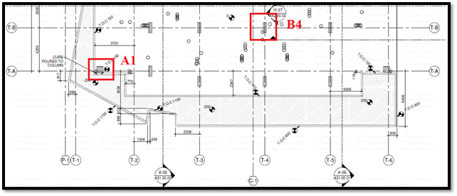
Superstructure Design
Substructure Design
References
[1] Truman Rentals . (n.d.). Seventeen West. Retrieved from https://renttruman.com/17west/
[2] Google. (n.d.). [Location of 17West Mixed-Used Development]. Retrieved from https://goo.gl/maps/gRE4Euws8jeBdira6
[3] Thwink. (n.d.). Three Pillars of Sustainability. Retrieved from https://www.thwink.org/sustain/glossary/ThreePillarsOfSustainability.htm
[4] Structure Point. (n.d.). Two-Way Flat Slab (Concrete Floor with Drop Panels) System Analysis and Design. Retrieved from
https://structurepoint.org/pdfs/Two-Way-Concrete-Slab-Floor-With-Drop-Panels-Design-Detailing.htm
