Project Category: Civil
Join our presentation
About Our Project
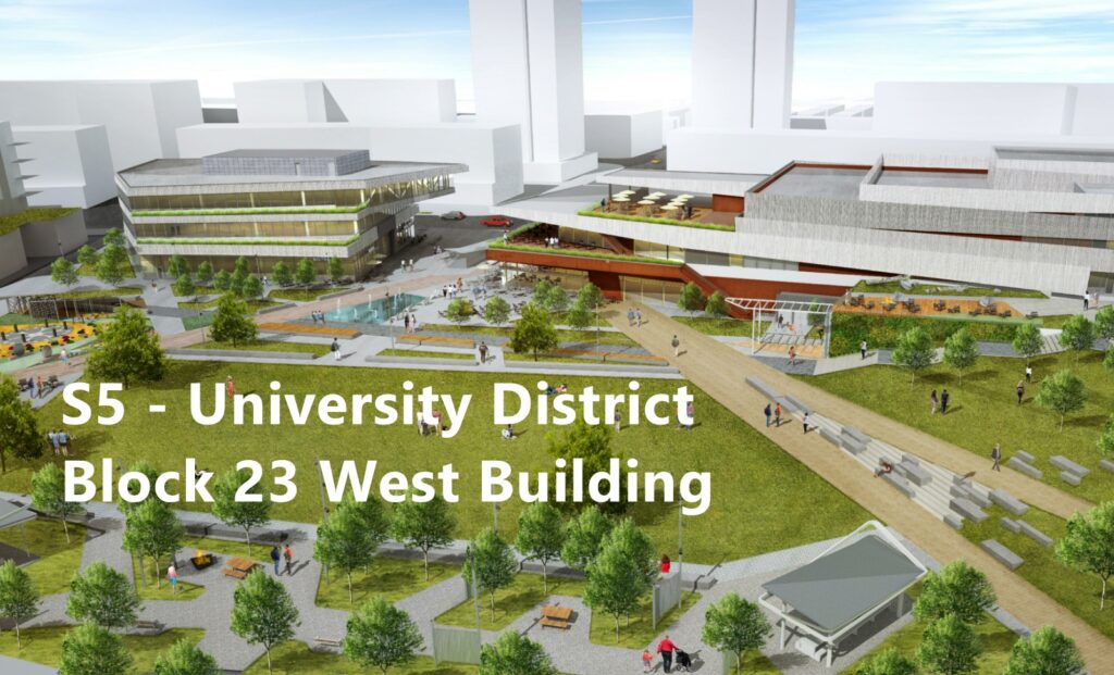
The three-story Block 23 West Building located in the University District of Calgary, Alberta. The University of Calgary Properties Group (UCPG) has planned for the development of two mixed-use buildings located in the University District. These buildings are the Block 23 West Building and East Building which share a common underground parkade and park area. The West Building is a complex that will provide spaces for offices, restaurants, and retailers. The development of the West Building is expected to be completed by the end of 2021 and will contribute to economic growth, the repurposing of under-utilized land, and create a more fulfilling community-style atmosphere for the University District. Elements considered by the Capstone group:
- Typical bay elements (columns, beams, slab) for each floor
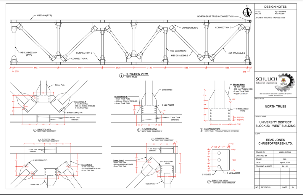
- Overhang (structural steel elements with connection to the concrete superstructure)
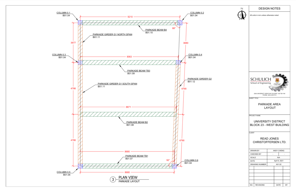
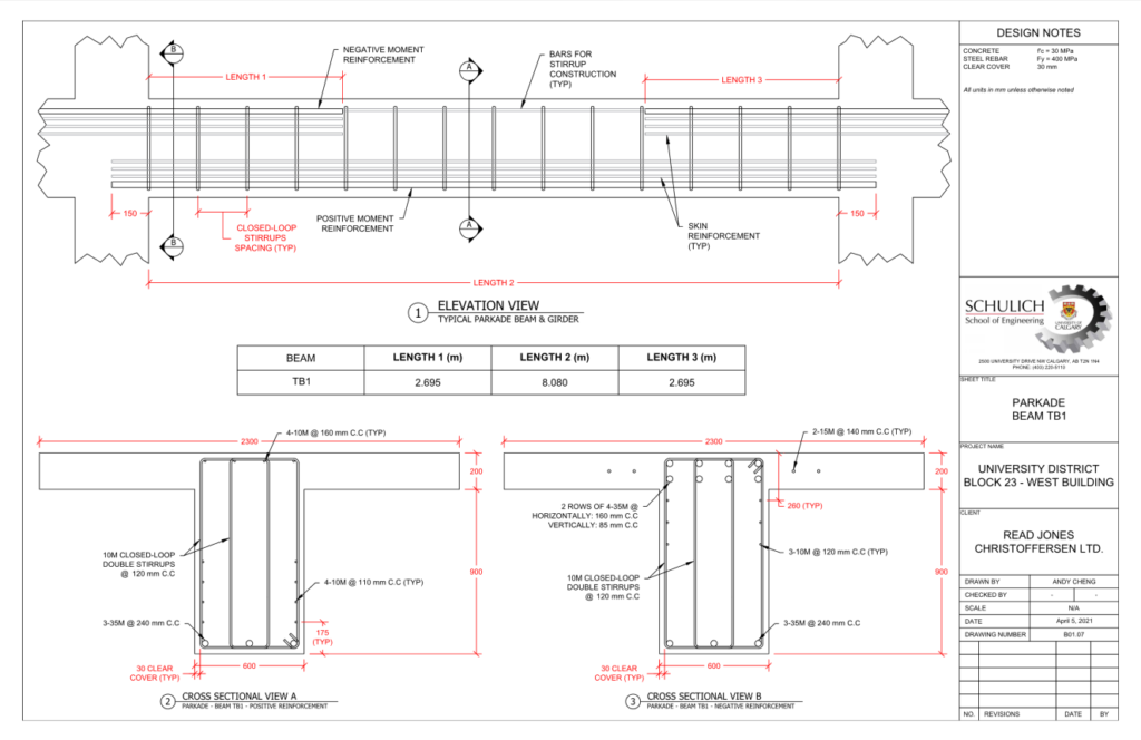
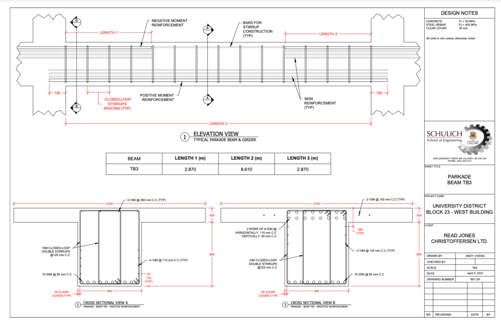
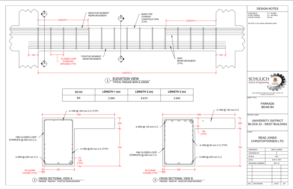
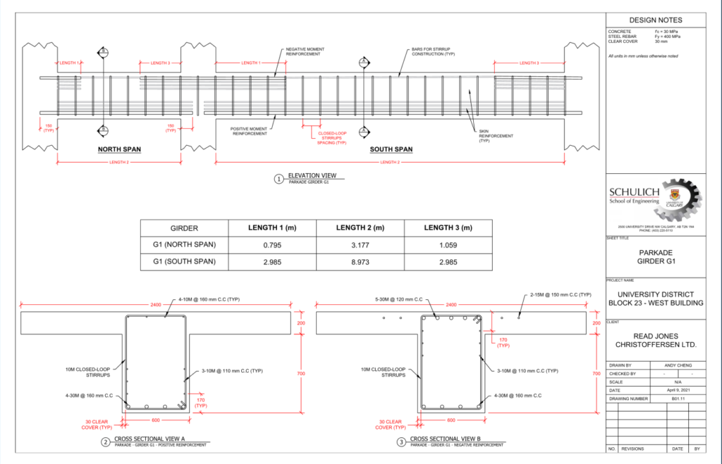
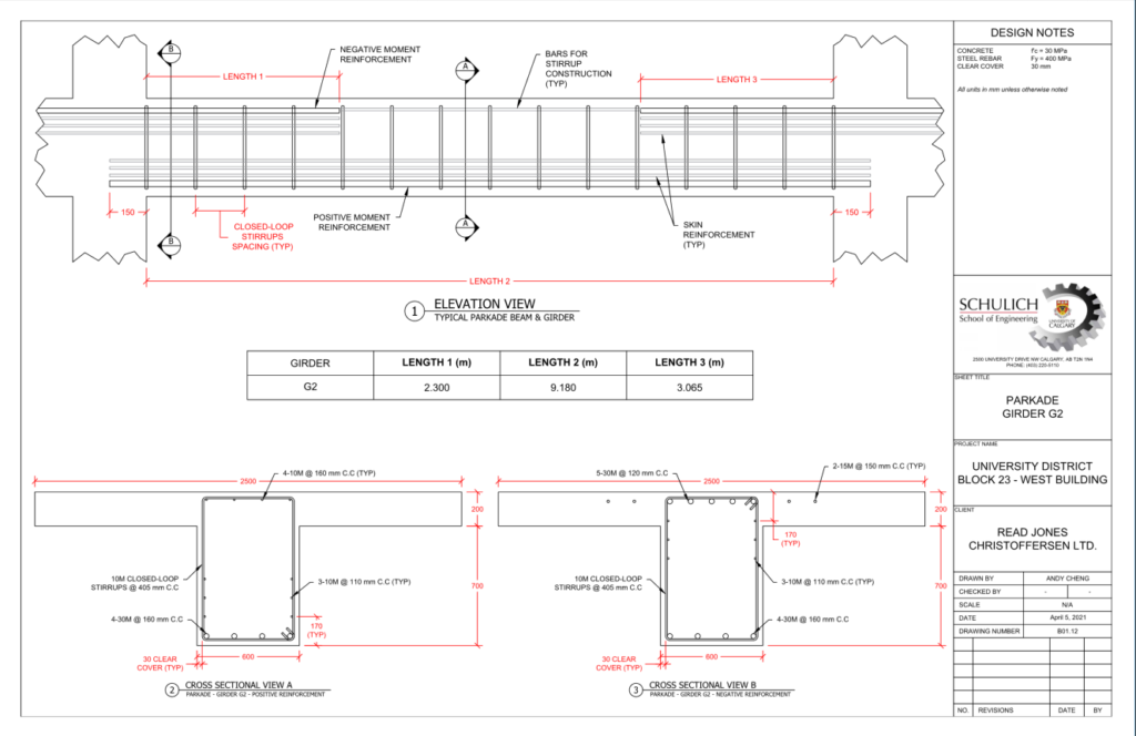
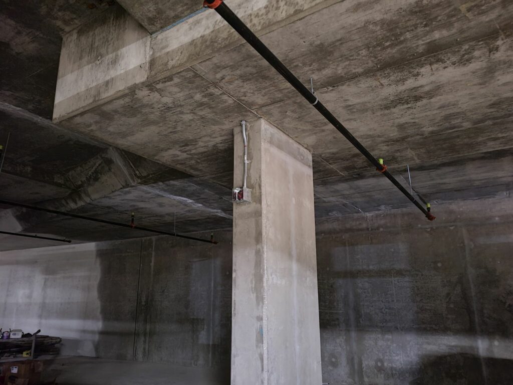
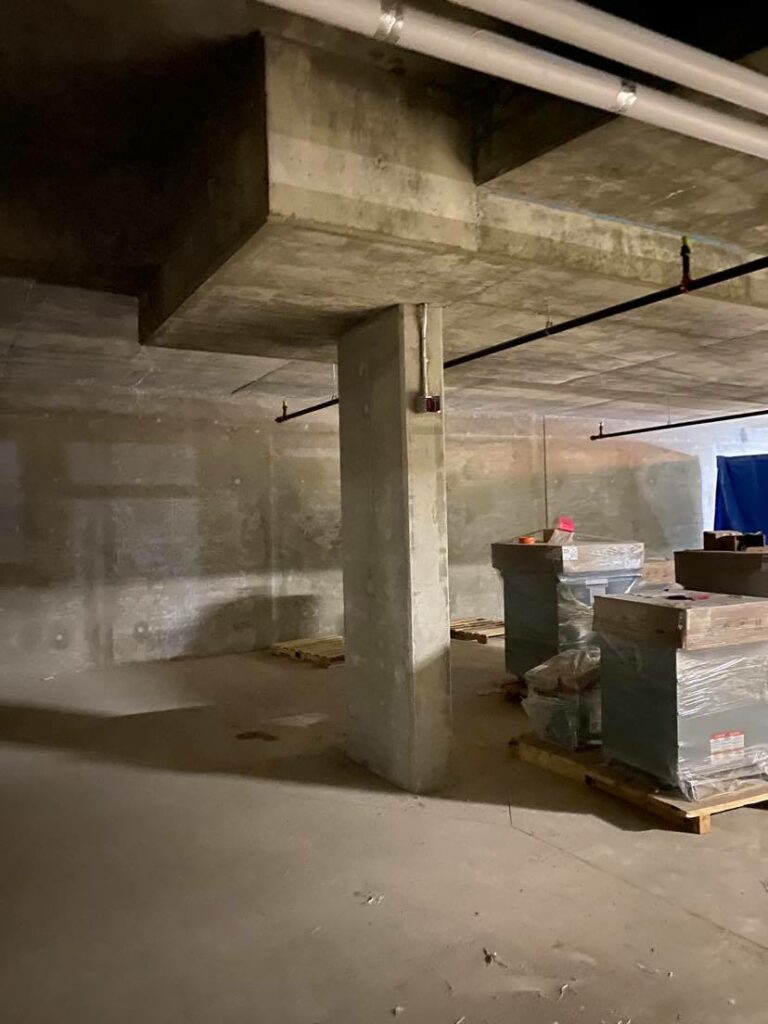
- The main floor transfer system (beams and girders transferring loading due to misaligned column placement in the parkade)
The goal of our design is to provide a feasible, cost-efficient, and sustainable solution to the structural requirements for the given architectural layout.

Meet Our Team Members

Li


Ma

Cheng

Muranets
Ngo

Chen

Day
Details About Our Design
HOW OUR DESIGN ADDRESSES PRACTICAL ISSUES
This project addresses several practical issues that arise in structural engineering projects. The overhang on the third floor creates a large cantilever load on the building, which we resisted with the use of a truss along the length of the overhang, and with a back span truss, spanning two-bay lengths to resist the load. The truss design was extremely critical, as it is both a major structural concern, as well as a significant concern architecturally. Due to a misalignment of columns between our first floor and parkade, we were required to design a main floor transfer system to transfer the load. The reasoning for the misalignment of columns is due to the parking stall locations dictating the orientation of the parkade columns. The main floor transfer system was designed as a concrete transfer girder and it is required at several locations in the building.
Overall Bay Model
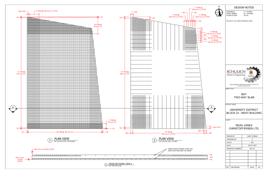
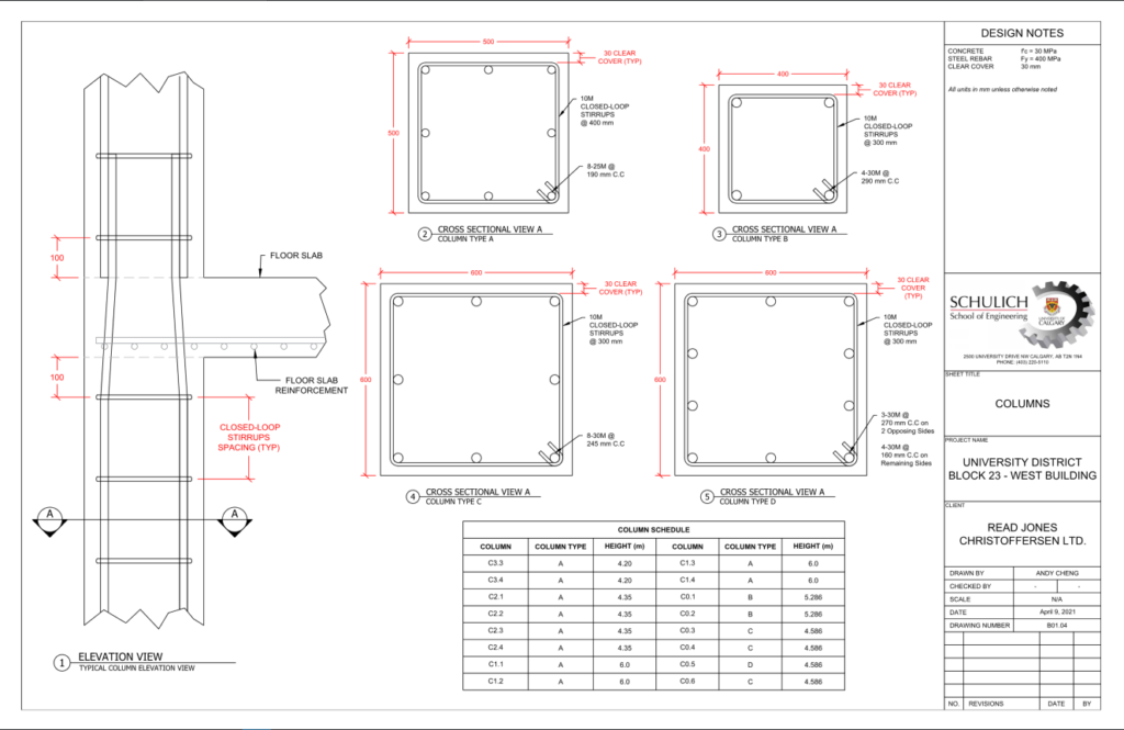
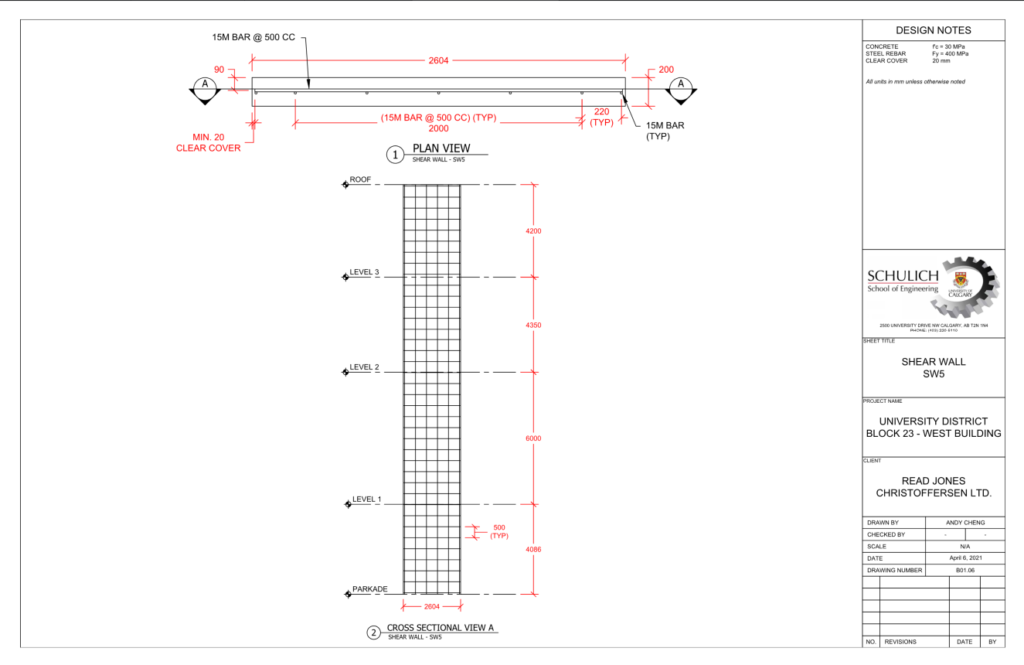
The main concern as a structural engineer involves designing both the lateral load resisting system and the gravity load resisting system. We designed several shear walls to resist the lateral loads in both directions, which are located around the center of the building. The gravity load resisting system we used consists of concrete two-way slabs, beams, girders, and columns, which transfer the load into the foundation. The soil foundation is relatively weak at this site which made the design of the foundation challenge. This issue was addressed through the design of larger shallow foundations, which can accommodate the low bearing pressure accordingly. In conclusion, our design properly addresses all the structural issues in a manner that is consistent with the industry standards and codes.
WHAT MAKES OUR DESIGN INNOVATIVE
For our capstone project design, we incorporated innovative designs primarily from two aspects: an architectural/structural perspective and from a sustainability perspective.
The unique geometry of the building and the need to adhere to the architectural plans presented various challenges in the design phase that required innovative and creative designs to address:
- The typical bay is not perfectly square and required irregularly shaped tributary areas.
- Certain columns do not fully extend through the entire building. Column misalignments require a transfer system on the first floor.
- The overhang requires a completely different design method and material compared to the rest of the building.
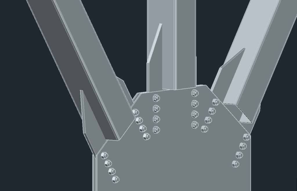
In particular, the overhang on the third floor presented challenges due to its shape which must be addressed using innovative designs, since the same concrete design method for the rest of the building cannot be used. The overhang was designed as a truss using HSS sections so it will be lighter weight, strong and able to resist the factored loads without excessive deflection. A truss design also allows for windows to be installed to adhere to the architectural plans.
Our design also promotes sustainability through innovative design by using green concrete for the foundation and columns, installing photovoltaic cells, and incorporating the use of windows. Green concrete has a high proportion of fly ash which increases the time required to reach its designed strength. Because the foundation and columns will not immediately experience the maximum designed load while the building is constructed, these elements are ideal to be cast with green concrete. Additionally, photovoltaic cells are to be installed to decrease the building’s operational carbon footprint print throughout its life. Finally, in addition to being an architectural feature, windows can allow natural sunlight to enter the building and even contributes to heating the building; although windows can also be a major source of heat loss during cold temperatures as well.

WHAT MAKES OUR DESIGN SOLUTION EFFECTIVE
In our design, we took into the consideration of available space, material and cost effectiveness. Transfer beams were strategically placed only at locations where there is a need to transfer the column loads from floors above. This reduces cost and provides more openness in the parkade. Furthermore, certain columns in the parkade were either removed or rearranged such that they are more evenly spaced apart to provide additional space efficiency and more balanced load distribution.
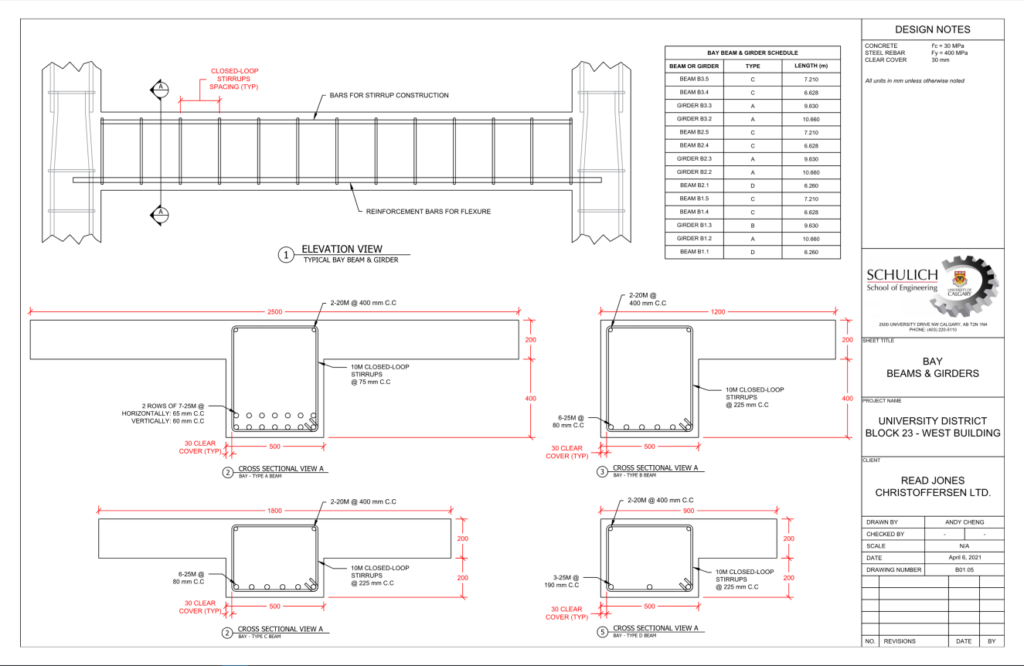
Another space effective feature in our design is that we did not use any columns in the main bay area to provide more usable space for tenants. Our bay design utilizes consistent dimensions and repeating elements throughout the three floors to simplify construction of the structure.
When selecting material and cross-sections, we minimized the use of steel in most of the buildings. Compared to steel, concrete was more cost-effective for the size of members designed and provides more flexibility in construction. In addition, we designed our overhang truss using square HSS steel members. These are more structurally favorable as they would reduce the superimposed dead loads due to their high strength-to-weight ratio. This is particularly crucial as the overhang is a self-supporting structure.
Overhang Truss
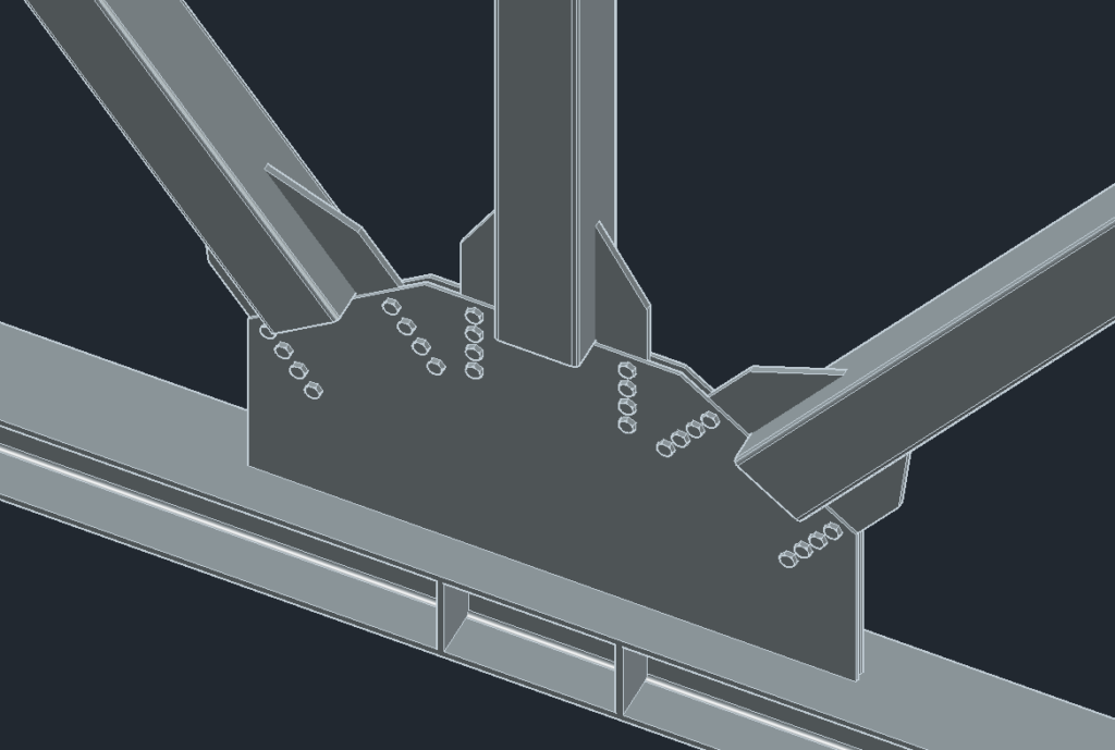

Typical Bolted Connections
HOW WE VALIDATED OUR DESIGN SOLUTION
The validation of our design solutions consisted of the following:
- Designing based on relevant codes and standards which include:
- National Building Code – 2019 Alberta Edition
- CSA A23.3-19, “Design of Concrete Structures”
- CSA S16:09. “Design of Steel Structures”
- Handbook of Steel Construction – 11th Edition
These codes set clear standards as to the minimum requirements that we needed to meet when conducting our design of the building. Relevant codes that we used consisted of safety factors, formulas to calculate resistive strength of members, deflection limits, etc.
2. Checking our design approaches and verifying our methodology with our group’s industry and academic advisors. Our advisors are experienced and knowledgeable in areas of structural design, as such, we explored any suggestions they made.
3. Utilizing software to verify finalized values after completing hand calculations. Software that we used were:
- AutoCAD
- Microsoft Excel
- SAP 2000
FEASIBILITY OF OUR DESIGN SOLUTION
To assess the feasibility of our proposed design for the West Building Complex the team first conducted a review of all technical requirements and available information about the project. We then researched outstanding information and compared designs of several alternatives before selecting our design solution. The feasibility of our proposed solution was evaluated based on constructability, risk, architectural intent, and cost. The chosen design solution aimed to minimize risk and cost while maximizing ease of constructability and adherence to architectural intent. To accomplish this, we incorporated typical elements that can be found in a multi-story complex such as beams, columns, and girders. We chose locally accessible materials for construction to minimize cost and designed the truss overhang to minimize the number of pieces that had to be bolted on site.
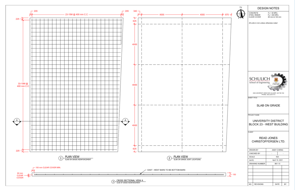
DRAWING SET



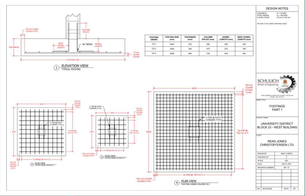

Partners and Mentors
We would like to thank our academic and industry advisors: Dr. Duncan, Dr. El-Badry, and Mr. Kevin Zwaagstra respectively, for their oversight and educational mentoring that helped facilitate our project success.


Our Photo Gallery
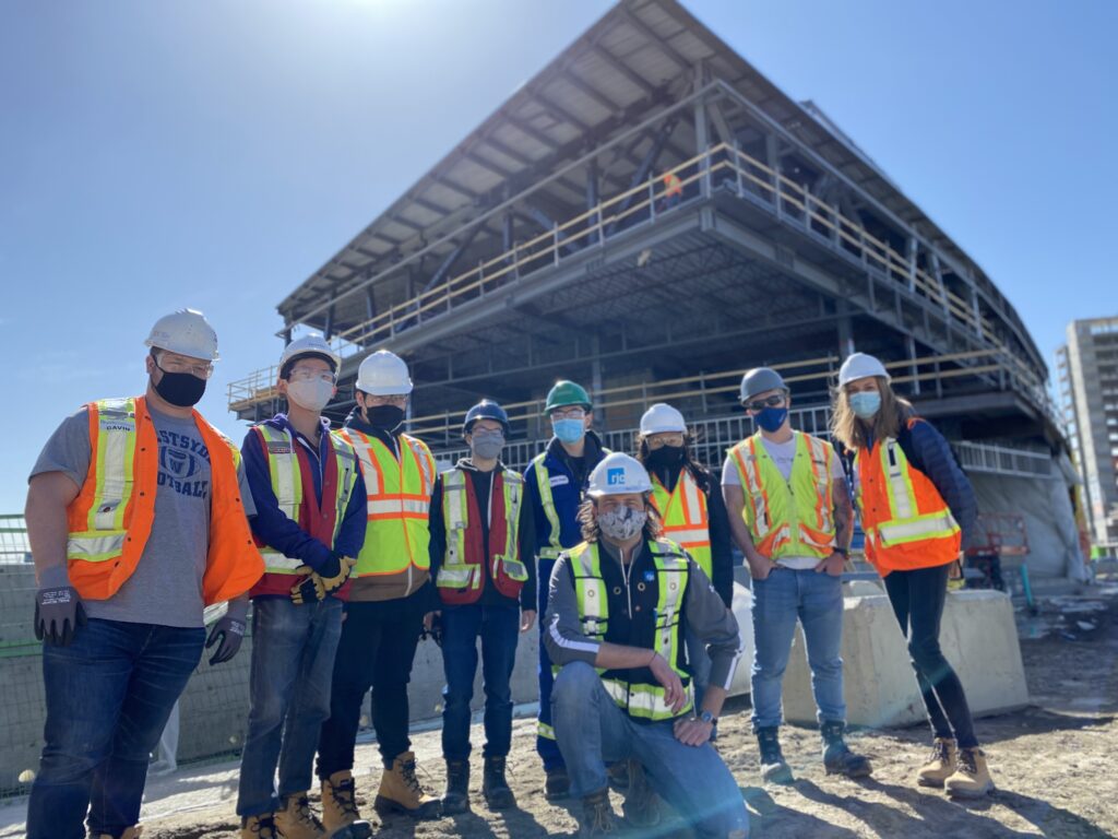
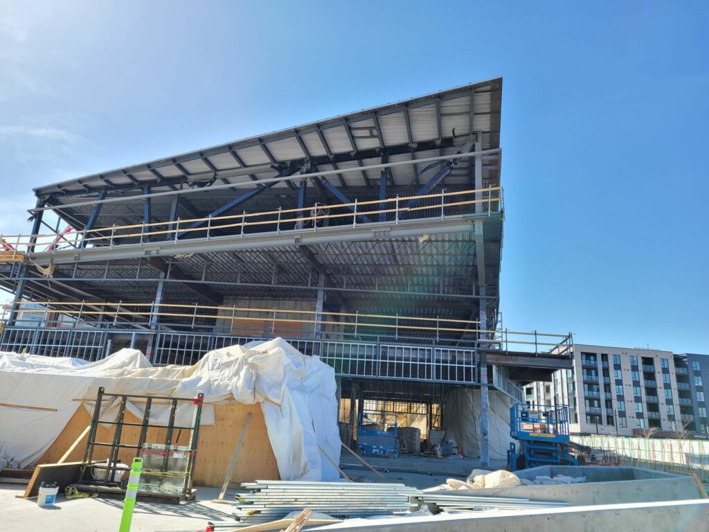
Overall View of The West Building
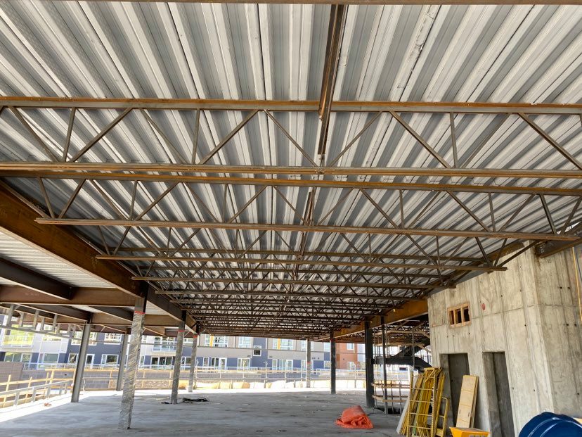
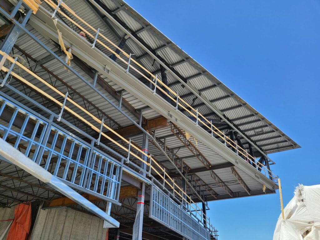
Beam Supporting the Third-Floor Overhang
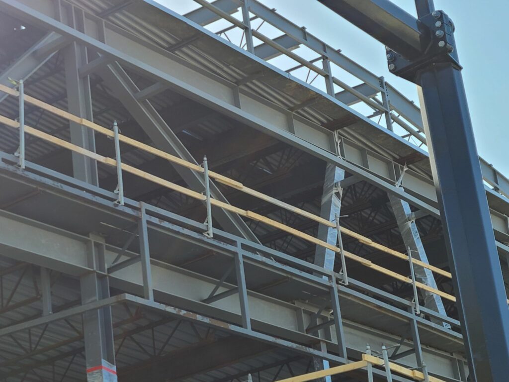
Truss On the Third-Floor Overhang
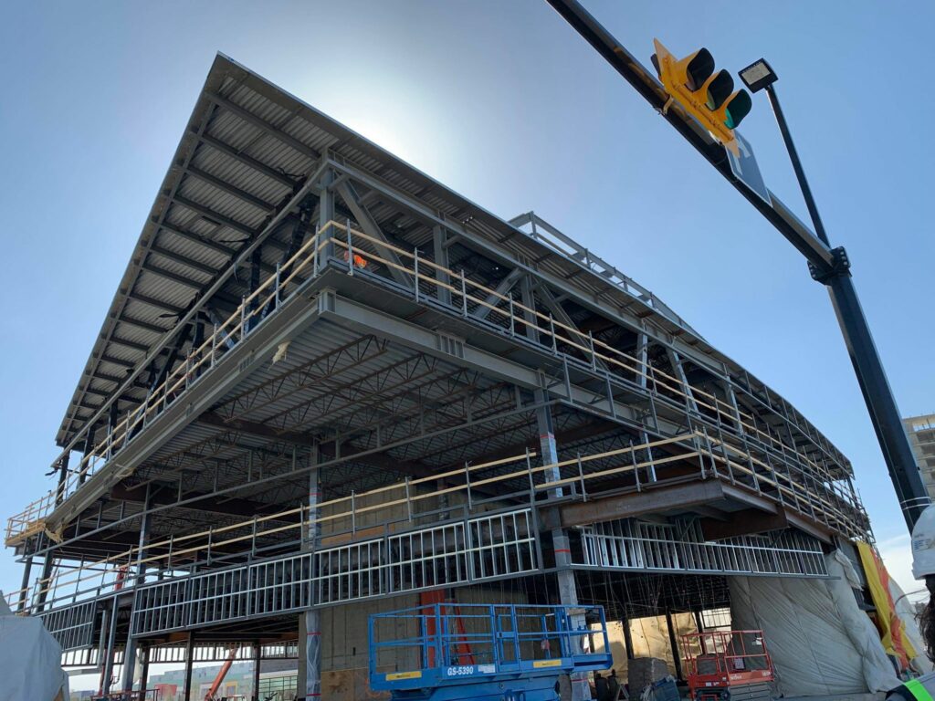
Overhang and Truss Support
