Project Category: Civil
Ask the team questions about our project here:
About our project
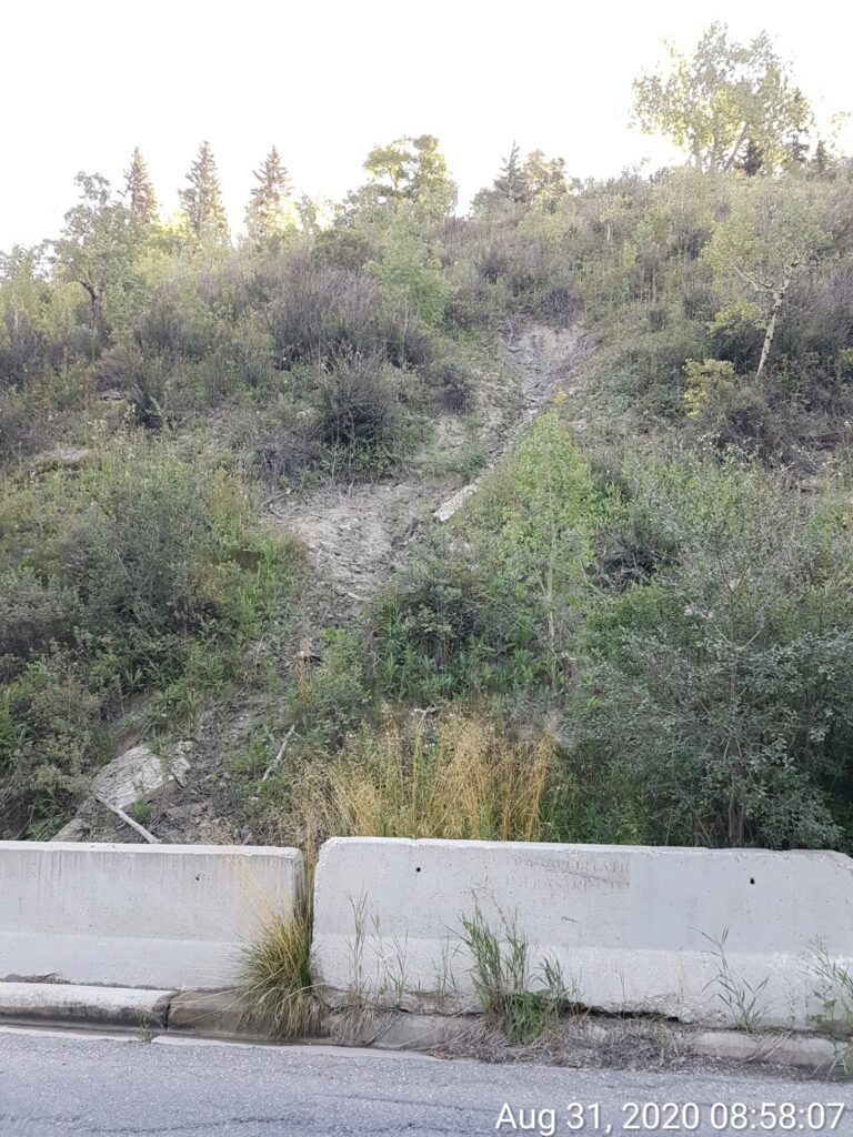
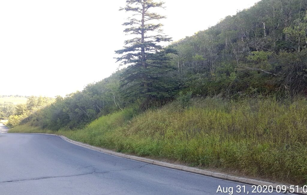
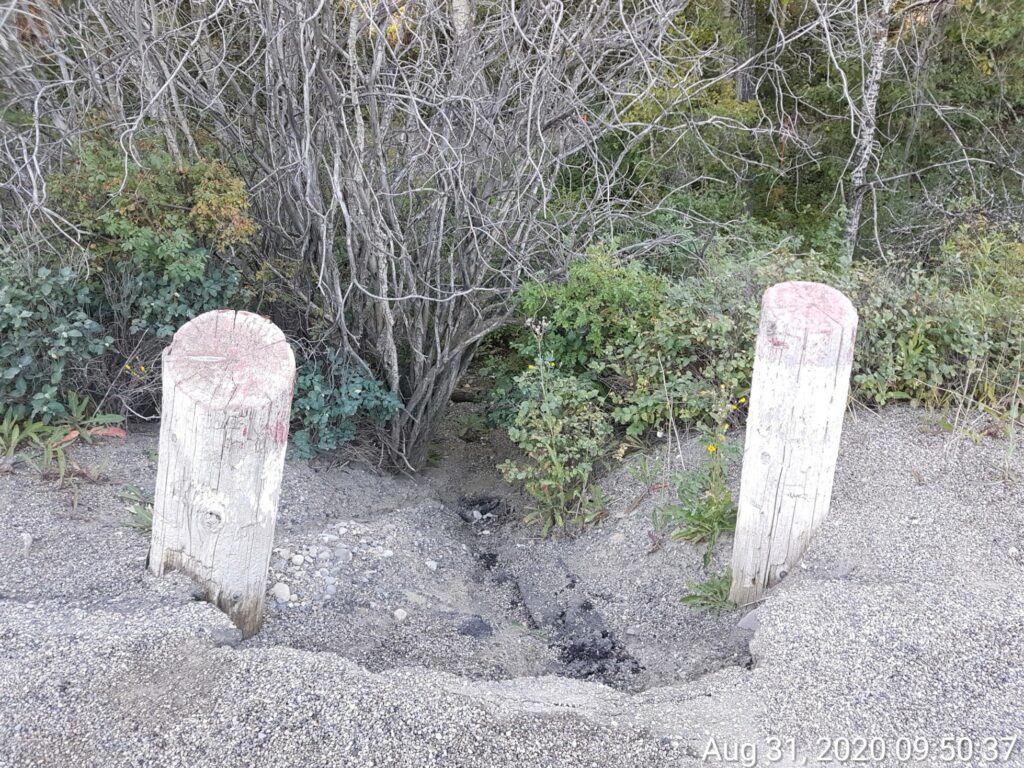
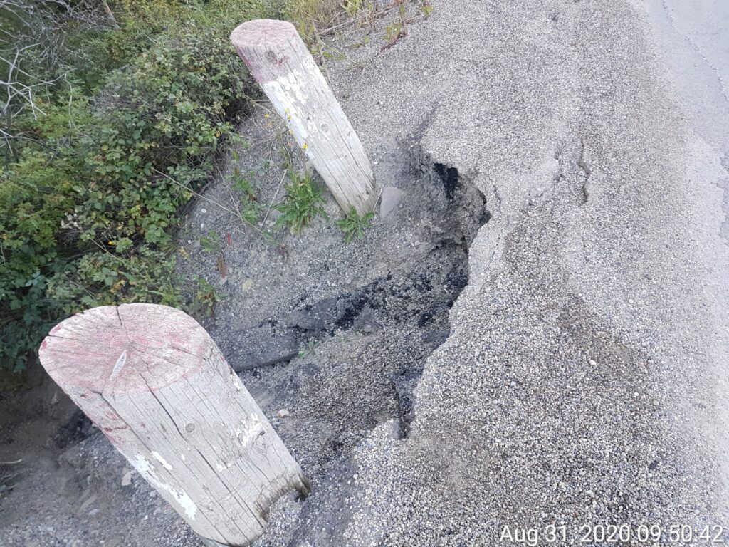
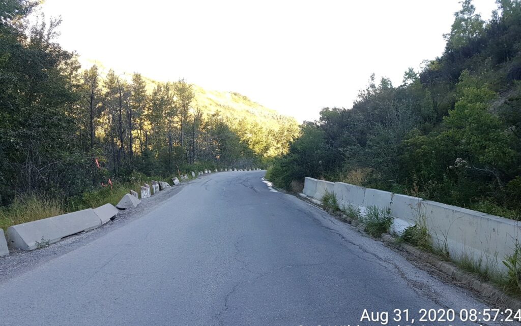
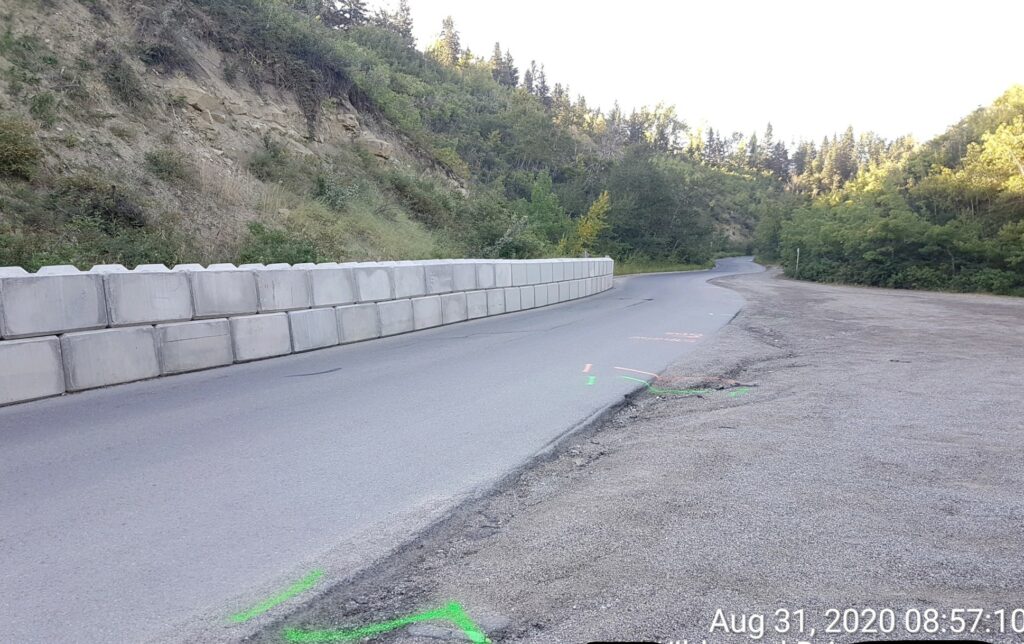
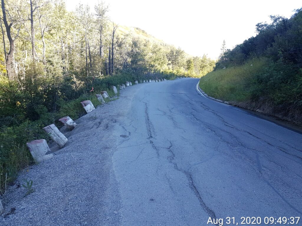
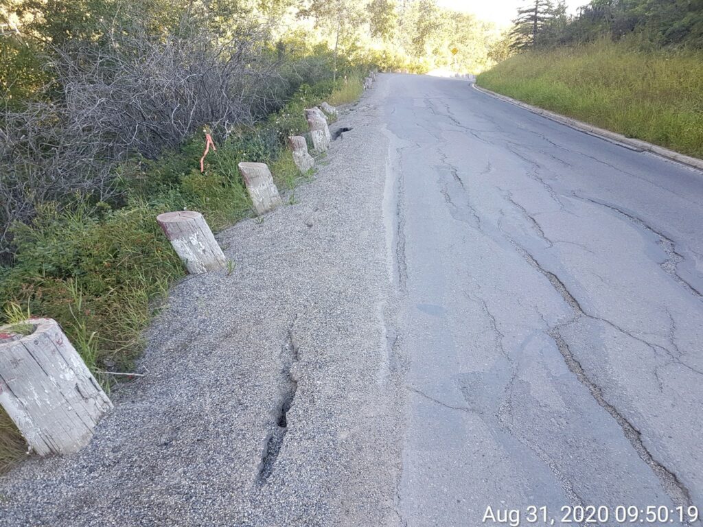
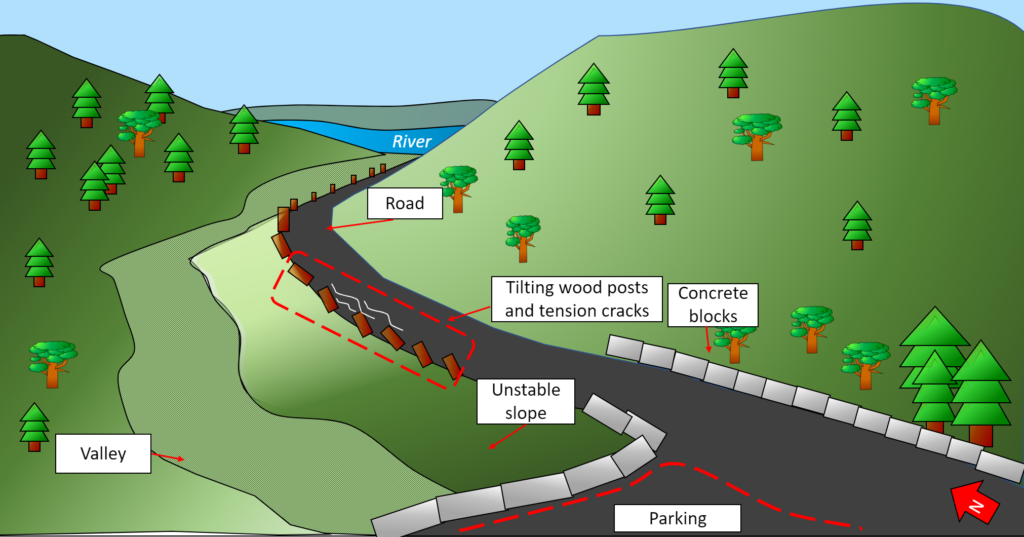
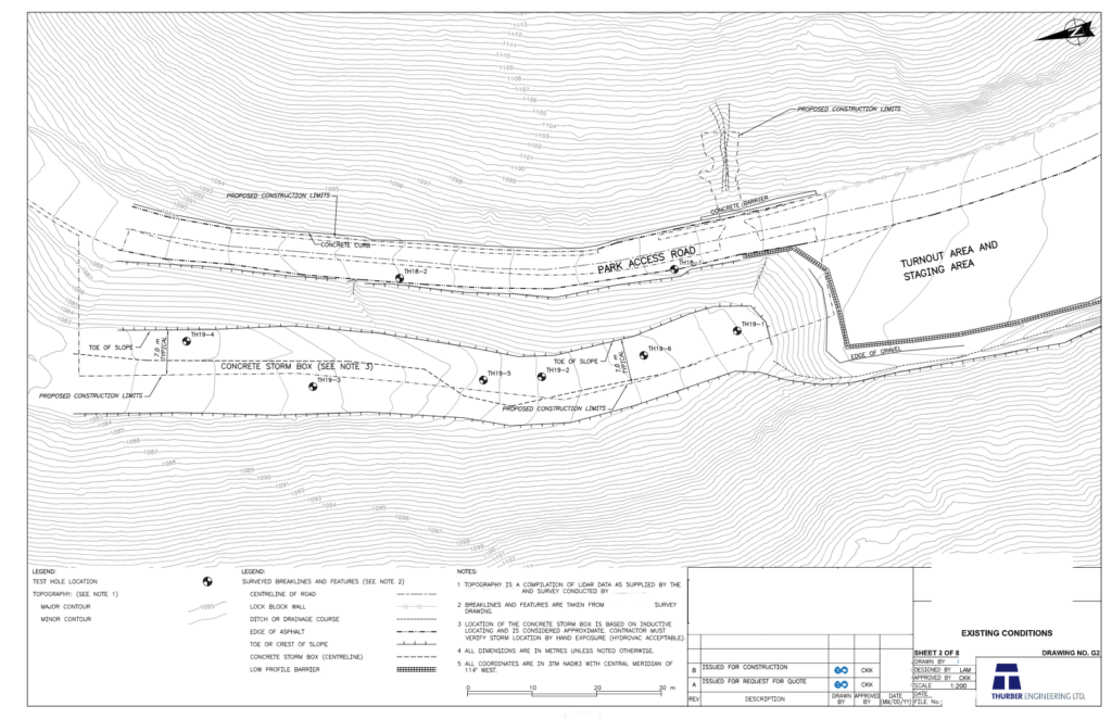
The City of Calgary (COC) has identified an unstable slope on the west shoulder of a road leading into the valley of a park located in SW Calgary. Evidence of surficial sloughing, tension cracking of the road and tilting of wooden posts along the valley indicate the slope’s instability. A geotechnical investigation of the site was conducted by Thurber Engineering. By analyzing the site’s borehole log data and performing a slope stability analysis, a failure mechanism (possibility of slope failure) was identified in the slope, with the need for slope remediation for the continued use of the access road into the park.
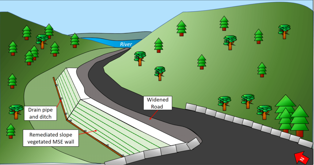
The Earthmovers designed a mechanically-stabilized earth (MSE) wall to ensure the stability of the slope is compliant with COC requirements and allowed additional ground clearance for a future road widening project. The wall features a sloped design with a vegetated exterior, allowing the wall to blend in with its natural environment.
Meet the Earthmovers


Design Parameters
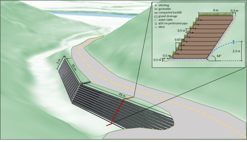
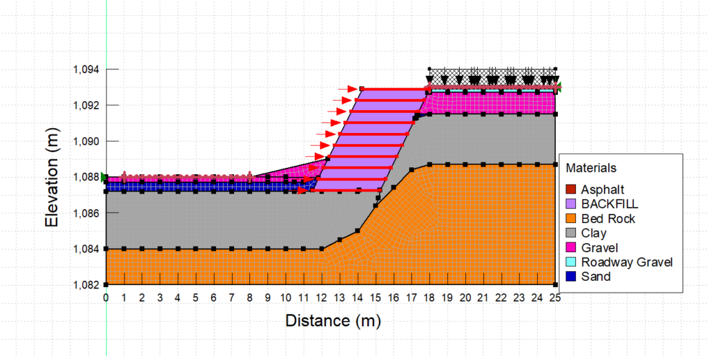
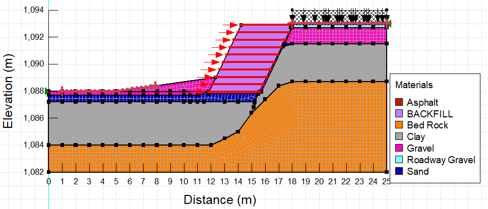
The retaining wall is a mechanically-stabilized earth wall made up of ten lifts. Each lift consists of geotextile material laid as the base and covered with a layer of backfill material, with the geotextile then being wrapped around the front of the backfill layer and stitched to another section of geotextile material to create the base for the next layer. A cross-section of the wall including specifications for each layer is shown in the diagram above. Additional Technical specifications are shown in the table below.
| Number of Lifts | 10 |
| Wall Slope | 64° |
| Lift Height | 0.5m |
| Lift Width | 4m |
| Lift Setback | 0.35m |
| Geotextile Overlap | 0.3m |
| Gravel Drainage Layer Width | 0.3m |
| Unit Weight of Backfill | 18 kN/m3 |
Details about our design
HOW OUR DESIGN ADDRESSES PRACTICAL ISSUES
Due to the nature of the site, with a wooded valley at the toe of the slope and a narrow road at the crest, space there is limited room for materials and equipment. After the initial excavation, geotextile and soil layers can be constructed by following a simple, repeatable process requiring a small team of workers.
Software analysis has been conducted for the intermediate steps of the construction phase to ensure the slope remains stable during construction, including the effects of seepage into the stability of the slope.
Additional loading that may be incurred by the wall due to the planned widening of the access road at the crest of the slope has also been considered. Our wall will remain stable and allow for the road to be widened by up to two meters.
WHAT MAKES OUR DESIGN INNOVATIVE
The following aspects of innovative design were influence by the COC’s guiding principles for the long-term vision for Calgary city parks, as outlined in the COC’s ImagineParks guide:
SLOPED DESIGN
A sloped design was chosen instead of a more traditional vertical MSE wall. This is advantageous to the site requirements and limitations as it minimizes the amount of material to be excavated from the slope. This is also a gentler landscape transition from the road to the valley below, making the landscape more please to park visitors and aligning with the principle of “Make people a priority”.
VEGETATED EXTERIOR
A layer of topsoil will also be added to the “steps” of the wall, allowing for vegetation. Upon completion, the wall will be a safe, aesthetically pleasing remediation method, blending into its natural environment. This aspect of the design aligns with the principle of “Conserve biodiversity and the natual environment”.
WHAT MAKES OUR DESIGN SOLUTION EFFECTIVE
DESIGNED FOR SAFETY AND STABILITY
Our MSE wall design adds stability to the slope. Adequate factors of safety are achieved for wall sliding, bearing capacity, overturning, and overall global stability as outlined by the COC. The design also addresses the future widening of the access road at the crest of the slope and will allow for the road to be widened by up to two meters.
| Criteria | Factor of Safety |
| Sliding | 1.5 |
| Bearing Capacity | 2 |
| Rotation | 2 |
| Global Stability | 1.5 |
CONSTRUCTION PROCESS
The construction methods required for MSE walls are repeatable. The layering of geotextile and backfill is simple. The process can be done in segments along the wall to streamline construction processes.
HOW WE VALIDATED OUR DESIGN SOLUTION
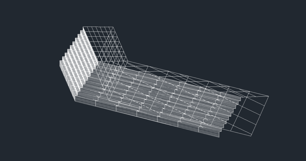
SOFTWARE MODELLING
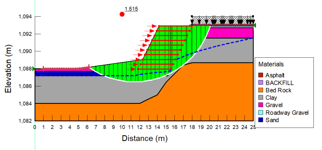
A geologic model was developed from site borehole logs in order to assess preliminary site conditions on the Geostudio platform. Our final design as well as intermediate construction stages were evaluated for global stability and seepage using this model. Global stability and drainage of our design were tested using this model.
ITERATIVE DESIGN GUIDED BY CODES AND STANDARDS
Wall specifications such as number of lifts required, slope angle, and geosynthetic material length were calculated using a trial-and-error approach. The Canadian Standards Association: Canadian Highway and Bridge Design Guide (CSAS6:19) was used to ensure the retaining wall design followed established guidelines. When additional information was required, the American Association of State Highway and Transport Officials (AASTHO) codes were referenced. Design specifications were iterated on until acceptable factors of safety were achieved for all external and internal MSE retaining wall criteria.
FEASIBILITY OF OUR DESIGN SOLUTION
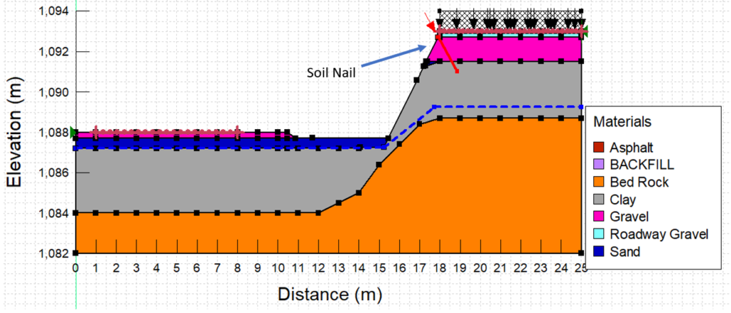
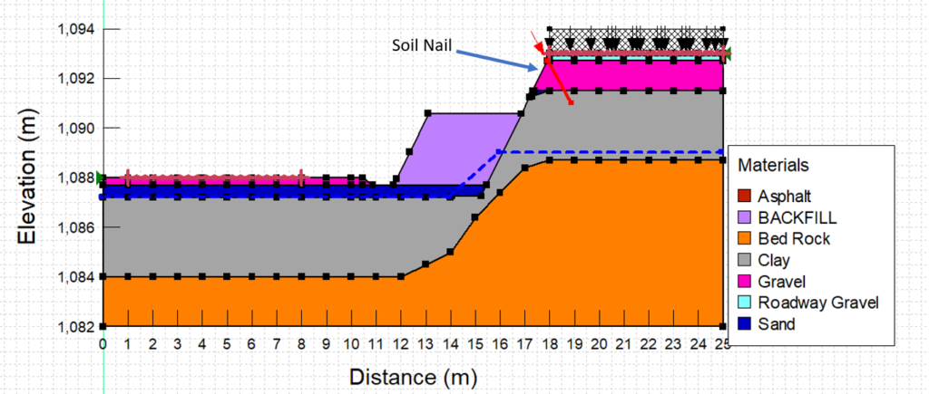
The construction process for the MSE wall was modelled in three stages: the slope after the initial excavation, after half of the lifts have been constructed, and the slope with the completed wall. Modelling and analyzing the stability of the initial excavation made it clear that additional slope stability measures would be required for the construction stages of the wall. We decided to add soil nails at the top of the slope in order to increase the stability of the slope after the initial excavation and ensure the access road would remain safe for use throughout construction.
To ensure the feasibility of our design the team researched local companies that supply materials required for MSE wall construction. Material specifications for the geotextile material was based on an option available from geotextile manufacturer Nilex in Calgary. Sourcing materials directly from local companies allows us to make more accurate cost estimations for our wall early in the design process.
Geologic Model
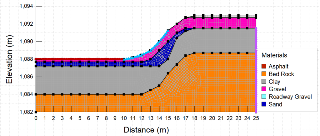
One of the biggest challenges for this project was creating the geologic model. Site-specific geology data was limited to nine borehole logs and a critical cross-section of the slope provided by our industry advisor and Thurber Engineering.
The soil layers were implemented from those found in borehole logs at the crest of the slope (the road), and the toe of the slope (the valley). Although the soil layers at these two points along the slope were known, we did not know how the soil layers manifested as the slope travelled down from the crest to the valley. Research was conducted into local geology was used to determine general stratigraphy in SW Calgary. A similar stratigraphy was then applied onto the critical-cross section to estimate soil layering that would be present on the slope. Upon consultation between the industry advisor and the team, it was decided that every GeoStudio analysis would be modelled using the critical cross-section to ensure the design would meet safety requirements along the entire slope in need of remediation. After various revisions, we developed the model shown below.

Material properties for each soil layer were determined from Soil Penetration Test (SPT) and Cone Penetration Test (CPT) values found on the borehole logs. Specifications for each layer are summarized in the table below.
| Soil Layer | Unit Weight (kN/m3) | Friction Angle (Degrees) |
| Clay | 27 | 29 |
| Sand | 15 | 32 |
| Gravel | 16 | 35 |
| Backfill (for wall construction) | 18 | 35 |
Partners and mentors
The Earthmovers would like to thank our advisors for lending their time and expertise to this project. We could not have completed this project without their guidance!
Academic Advisor: Dr. Richard Wan
Industry advisor: Charles Kwok, Thurber Engineering
Our photo gallery