Project Category: Civil
Join our presentation
We are available for questions via Zoom from 10 AM to 12:30 PM.
About Our Project
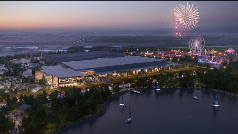
The Exhibition Park is the fourth oldest Agriculture Society which has been hosting events for over a century. The Park will receive a long awaited expansion and upgrades to further grow the community. The Exhibition Park will have four exhibition halls, three conference rooms, four meeting rooms, and a celebration venue as well as administration and office space. The stakeholder for this project is Exhibition Park.
Within the fall semester, the team split into two smaller groups to take on this project. Each group will focus on a specific structural system within the Exhibition Park. The first group, who included Geer, Sara and Ophelie, designed the two-story office/event center space. This section includes block 1 and block 4 that has a conference entrance, lakeview salons, meeting rooms and a mechanical room. The second group, who included Nur, Nida, Alex and Janae, designed the Exhibition Center. This includes block 2, 3, 5 and 6 (known as the Exhibition Halls), prefuntion corridor and back corridor. Each group presented two structural system designs consisting of joists, beams, trusses, columns, second floor slab and roof framing, then a cost-benefit analysis was performed to see which design option was the best. The main determining factors was weight, cost, materials, sustainability, ease of construction and lateral bracing needed.
In the winter semester, we focused on finalizing the design we have chosen in the fall semester. After it was finalized, the lateral load resisting system, roof diaphragm, connections, concrete block/shear walls, foundation piles, slab on grade and grade beams were all completed during the winter semester. The team was split up to many smaller teams in order to design all of the stated topics.
Click “VIEW OUR VIDEO” for a quick visual overview of our project!
Meet Our Team Members

Details About Our Project
HOW OUR DESIGN ADDRESSES PRACTICAL ISSUES
The two main practical issues that our team considered in the project were time and cost. To address the practical issues our team opted to use a design that would require the least material to satisfy the structural requirements. To find the optimal design, we came up with multiple layouts for the gravity load system. The gravity load system which consists of steel beams, girders, and trusses were selected based on the criteria that required the least members used. Choosing the optimal system not only reduces the cost and material but will reduce the time of construction. Having fewer members will result in fewer connections and less time required to connect all the members on site. We used this process for the different sections of the building, exhibition hall, and office areas. For the lateral system, the roofing diaphragm took on part of the lateral loads from wind loads, which reduces the amount of lateral support needed. Rigid connections for the lateral system are more expensive and takes more time to construct and were avoid as much as possible. The use of lateral bracing was prioritized due to its relatively easier connection and is less expensive.
WHAT MAKES OUR DESIGN INNOVATIVE
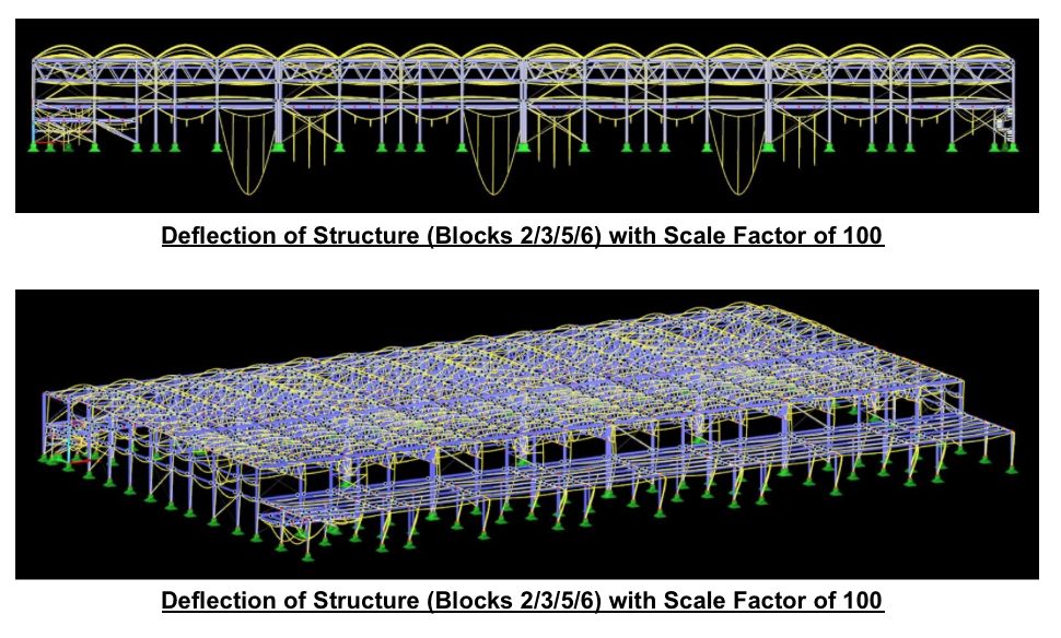
Our design is innovative because we considered many different types of materials throughout the building and designed based off the windy weather that Lethbridge encounters. We used a software called Dlubal to model the structure of our design, as it evaluates the load and wind on the building which was further used in the design process. The building consisted of many aspects that needed to be designed such as the precast concrete panels, concrete masonry walls, concrete foundation piles, and the steel framing. Therefore, the team explored the advantages and disadvantages of each material that could be used for each topic. With the knowledge we learned from school, our internships and doing our own research, the team was able to chose and design to the needs of the building and the people who would be using it.
WHAT MAKES OUR DESIGN SOLUTION EFFECTIVE
Our design solution is effective because we researched many different approaches to our solution and identified the best and most economical solution. We started with having two different designs for the joist, beam, and column layout and ranking them based on how economical they were and how easy they were to build. Based on the chosen final design, we started with the most economical design for the connections, bracing, walls, and piles, which we then adjusted depending on the structural analysis (for example, the design for the connections started as bolted connection since bolts are more economical than weld). Careful consideration was given to the type of material we used and it’s sustainability. We used structural analysis programs (like Dlubal RFEM and IDEA StatiCa) to double check all of our hand calculations and ensure the safety, stability, and performance of the building.
HOW WE VALIDATED OUR DESIGN SOLUTION
We have taken multiple steps to ensure our design solution is valid and correct. At first, the designs for each part (connections, piles, walls, etc.) were performed by hand using calculations and concepts learned within our university courses as well as referencing all other design codes such as the Canadian Standard Association (CSA) Concrete Handbook, Handbook of Steel Construction, and the National Building Code (NBC). Once we had completed the designs, we were able to model them using software to make sure our designs did not fail and met all design requirements. Some software we used to assist us in design are S-Foundation, S-Line, Dlubal, etc. Our design was further validated by consulting advisors and incorporating their feedback to ensure its practicality and real-world applicability. Our initial design, completed using hand calculations, served to teach us the theory behind our design before utilizing software to confirm it. This allowed us to enhance our theoretical knowledge while taking advantage of all available resources.
FEASIBILITY OF OUR DESIGN SOLUTION
Prior to starting a project, site appraisals with soil and borehole information are important because it determines what type of foundation is required. The geotechnical report was given to us and deep foundation piles were designed to accommodate the soil strength.
In terms of economic feasibility, due to the large size of the project, the team was advised that calculating the exact costs of our design is not within our scope. However, as mentioned in a previous section, the chosen design is effective while being sufficiently structurally stable. Because the selected structural members are standard and conventional, they should be readily accessible and affordable.
Another important factor is feasibility would be the constructability of our design – that is, if it is possible for general contractors to construct the building. Since the design contains typical structural members that have been used in previous projects, it is reasonable to assume that construction execution is possible used case studies as examples.
Standard construction procedure for structural members in our project would start with the foundations, then the structural steel and metal deck. The slab on grade and slab on deck would be poured when applicable. Masonry block would commence, followed by the exterior steel studs. The primary focus at this stage in construction would be on closing up the building to start the building envelope.
Details About Our Design Process
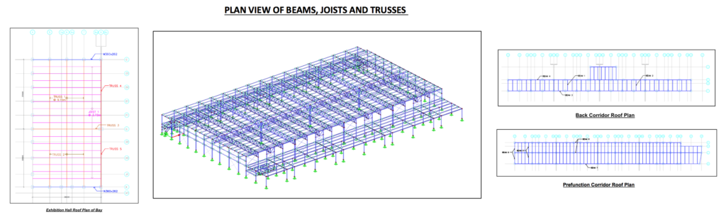
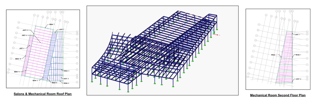
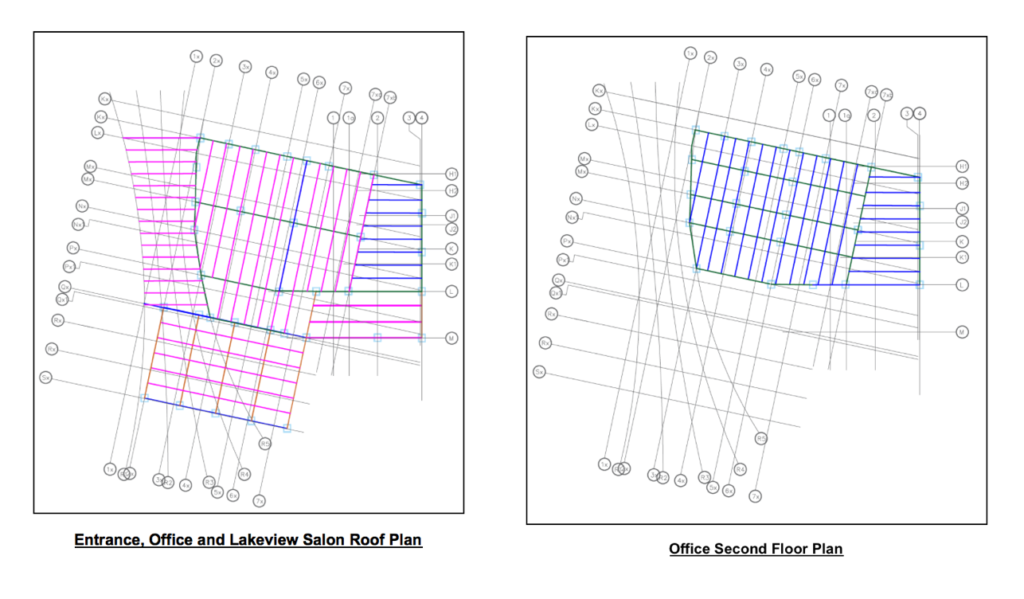
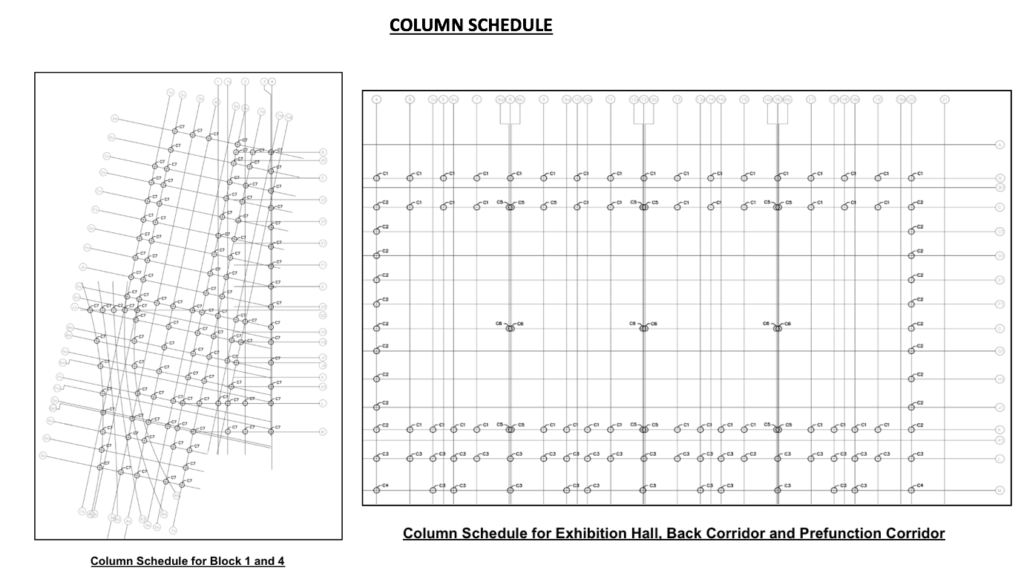
BEAMS, JOISTS, TRUSSES, COLUMNS
After selecting the material to be used in our designs, we moved on to the design process, which included determining the loads that were applied to the general roof and second floor plans. The selection of the type of roofing and flooring, as well as the types and sizing of sections were picked, which included beams, joists, and trusses. The columns were designed afterwards. This design was done during the fall semester but finalized during the winter semester. Refer to the photo gallery for the column schedule and the plan layouts of the Exhibition Hall, Back Corridor, Pre-Function Corridor, Salons, Mechanical Room, Office and Lakeview Salons.
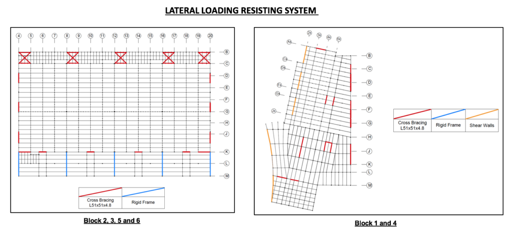
LATERAL LOADING RESISTING SYSTEM
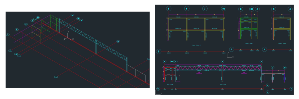
The lateral load resisting system (LLRS) consists of a combination of diaphragms, vertical cross bracing, rigid frames, and shear walls. Although the design of the LLRS is typically based on both wind and seismic analyses, only wind loads were taken into consideration for the purposes of this project, which is reasonable as wind loads govern over seismic loads in Lethbridge, Alberta. The wind loads were determined according to the static procedure or section 4.1.7.3 of the 2019 NBC(AE).
In order to transmit the wind loads from the roof to the vertical LLRS, the roof of the building was designed as a diaphragm. The specifications and design procedure in the Canam “Steel Deck Diaphragm” catalogue were followed to determine the correct size, type, and spacing of fasteners to ensure that the roof deck is rigid enough to act as a diaphragm, shown in the Photo Gallery as Diaphragm Design: Exhibition Halls.
In the exhibition centre, cross bracing was placed wherever architectural constraints permitted. Most of the cross bracing was focused in the walls of the exhibition hall since they had minimal openings, with some in the “back of house” corridor. In the pre-function corridor, rigid frames were used in lieu of cross bracing due to architectural constraints.
The office & salons relies on the lateral load resisting system of the adjacent exhibition centre for stability in the east-west direction. For lateral load resistance in the north-south direction, cross bracing was placed in the wall shared between the two areas of the building, as well as concrete block shear walls.
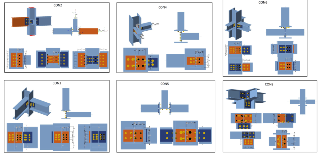
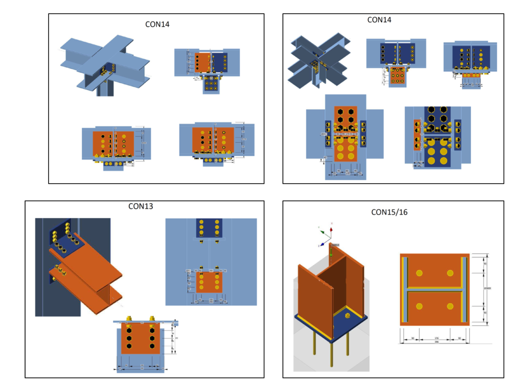
CONNECTIONS
Connections are very important structural elements that join different members together. As there are numerous connections within the building, the first step in our design process was to select a frame and group connections that were similar in load and configuration and create typical designs. Common configurations within our building include beam-to-column, beam-to-beam, OWSJ-to-column and column-to-base plate. Two main types of connections include bolted and welded connections, and they would be checked for their respective failure modes such as shear, bearing, tension, and material failure.
PRECAST CONCRETE PANELS & CONCRETE MASONRY WALLS
Two exterior walls that we designed for the Lethbridge Exhibition Hall are precast concrete insulated sandwich panels and concrete masonry block walls.
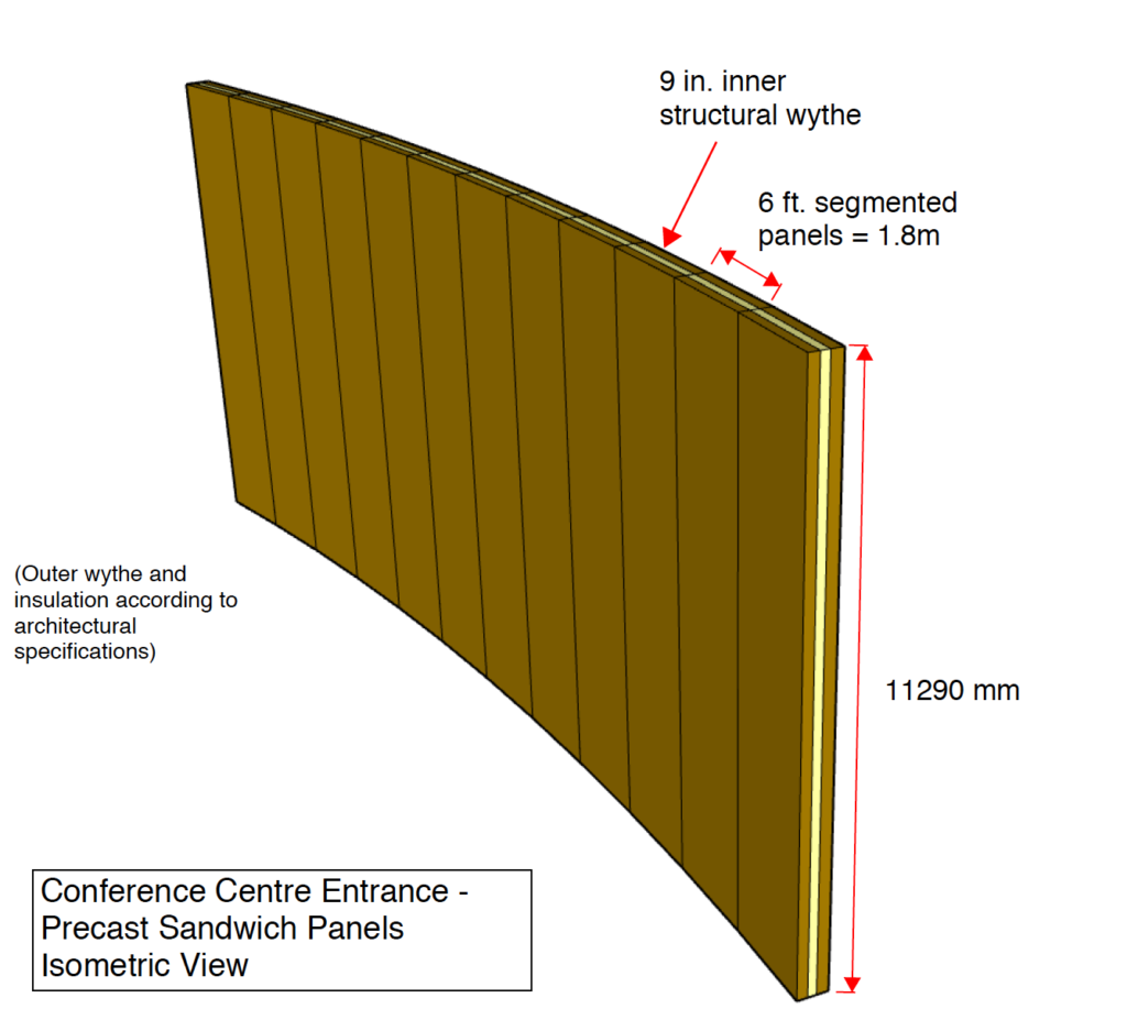
The precast panels are located along the exterior of the salons as well as at the entrance of the conference center. These precast panels are designed to be load-bearing, and must withstand the gravity loads from the roof along with lateral wind and seismic loads. The panels have an exterior wythe, an intermediate insulation layer, and an interior thicker wythe which acts as the primary structural member of the wall. Using the given loadings, the thickness of the interior layer was calculated and connections were designed.
The precast panels in the salons had a lower height and allowed for longer length panels. However, at the entrance the panels were designed to appear to have a curvature. Since curving precast concrete was not recommended due to the costs and practicality, it was decided for each segmented panel to be built at an angle to create the impression of a curving wall. These panels needed to have a greater height, and thus they were shorter in length and also thicker to accommodate a greater self-weight.
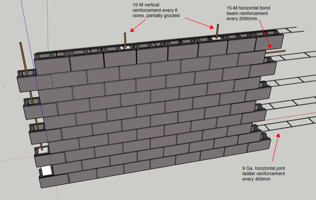
One of the exterior walls in the exhibition hall were designed to have an interior layer with 2700 mm high concrete masonry wall and steel stud resting on top, and an outer layer with brick veneer and insulated metal panels. These walls were designed to be non-load bearing due to the beams at the top transferring the forces to the columns, but the wall was required to resist lateral wind and seismic forces, along with their self-weight.
Another exterior wall on the east side of the exhibition centre was designed to have concrete masonry brick wall going from ground floor to the underside of the second floor. Special attention was needed to accommodate for the L-shaped and T-shaped configuration, and having a taller height than the previous concrete masonry walls.
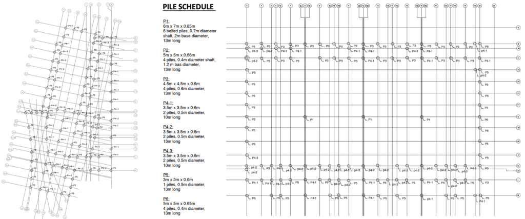
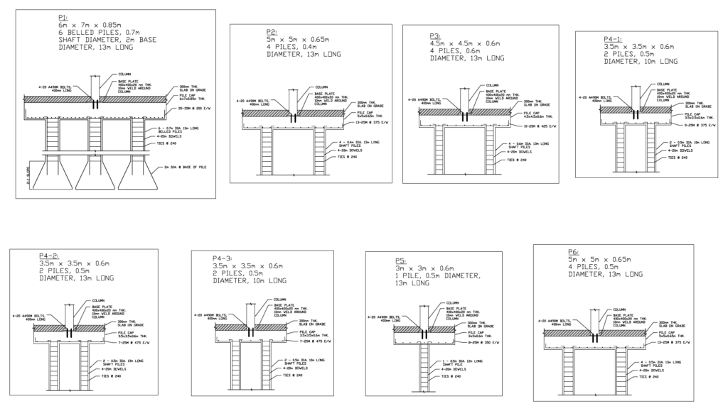
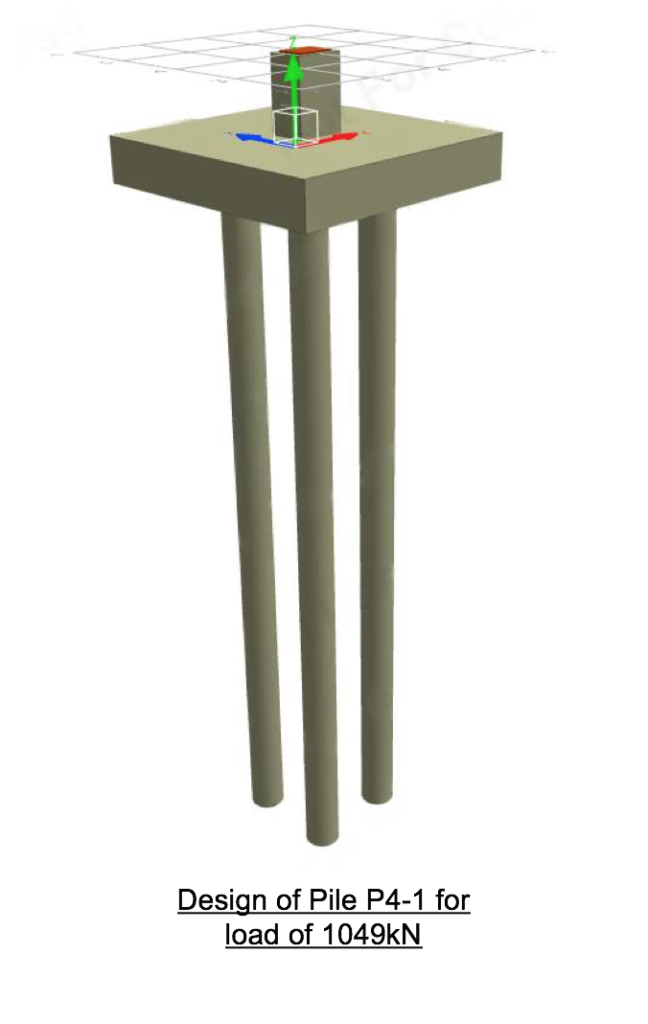
FOUNDATION PILES
The piles are used as a medium to transfer the gravity load and lateral loads to the ground. We determined all the column loads in the building and grouped the loads into seven groups. The groups are determined by how close the loads are. For each group, we designed a pile cap and piles for the highest load in the group. We checked one-way, two-way shear, and the bearing capacity of the concrete. These checks are guided by the CSA concrete handbook to ensure the concrete can withstand the load. We also designed the flexural reinforcement in both directions for the pile cap. After designing the pile cap, we determined the number of piles, pile diameter, and length of piles. The piles are calculated and checked to withstand the total load from the column loads, pile cap weight, grade beam loads, and wall loads.
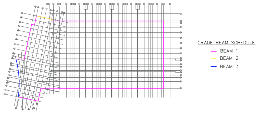
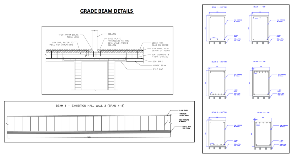
SLAB ON GRADE & GRADE BEAMS
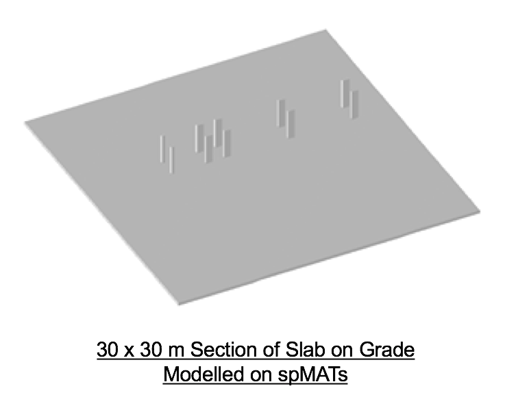
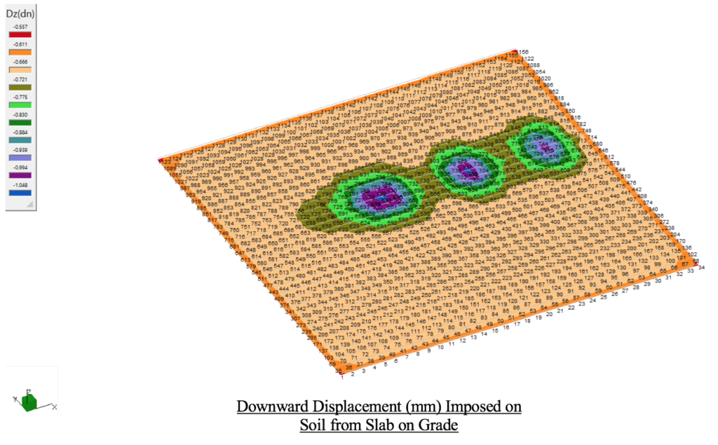
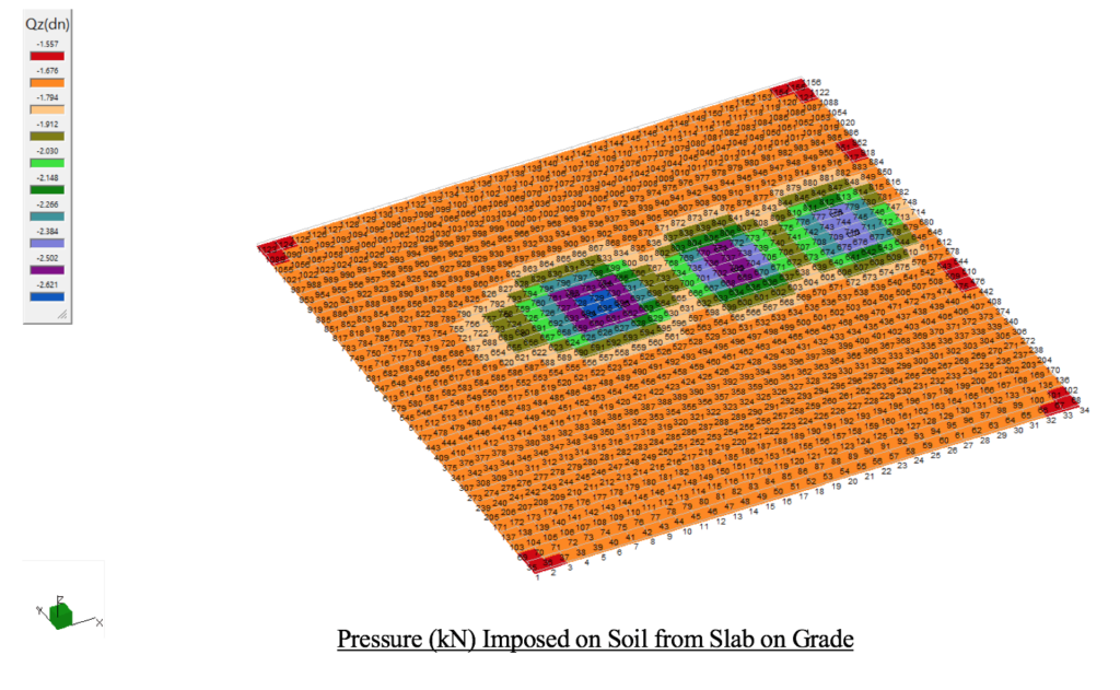
The slab on grade is a concrete foundation that lies on top of the ground. While designing the slab on grade, heavy truck loads needed to be considered. The exhibition hall would hold many different types of events in the future. As a result, multiple vehicles and trucks would be driven into the exhibition hall to be able to set up for these events. Therefore, the slab on grade had to be designed so it can withstand a heavy truck load. The CL-625 truck loading was used in order to determine the loads from the truck that would be applied on to the slab. Once the loading was determined, the slab thickness was calculated, and a section of the slab was modelled on spMATs. The CL-625 wheel loads, live loads, and the nodal springs were all modelled on the software to be able to determine the downward displacement and the pressure being applied to the ground below. The values obtained were compared with the maximum displacement and pressure values given to us within the geotechnical report.
A grade beam is a concrete reinforced beam that runs along the perimeter of the building. The purpose of the grade beam is to transfer the loads from the structure to the ground. The grade beam connects the outer piles and transfers the load from the walls to the pile caps. We started the design of the grade beam by determining the loads from the exterior walls and drawing the bending moment and shear force diagrams. We were able to identify the highest positive and negative moments as well as the largest shear force being applied to each span of the beam. These values were then used to design the flexural and shear reinforcements. Three different beams were designed with different reinforcements in order to accommodate the different loads from the building. A void form of 100mm was applied to the bottom of all beams. Void forms are there to provide space between the concrete and the soil. The void form is put in place to provide space for the soil to expand without cracking the concrete. It also helps support the concrete as the concrete cures and strengthens.
Partners and mentors
We appreciate and want to thank the people who helped us with this project. Our civil engineering professor, Dr. Raafat El-Hacha, and our industry advisor from DIALOG, Gamal Ghoneim, who guided us through the design process with knowledge and great advice.

Our Photo Gallery