Project Category: Civil
Join our presentation
About our project
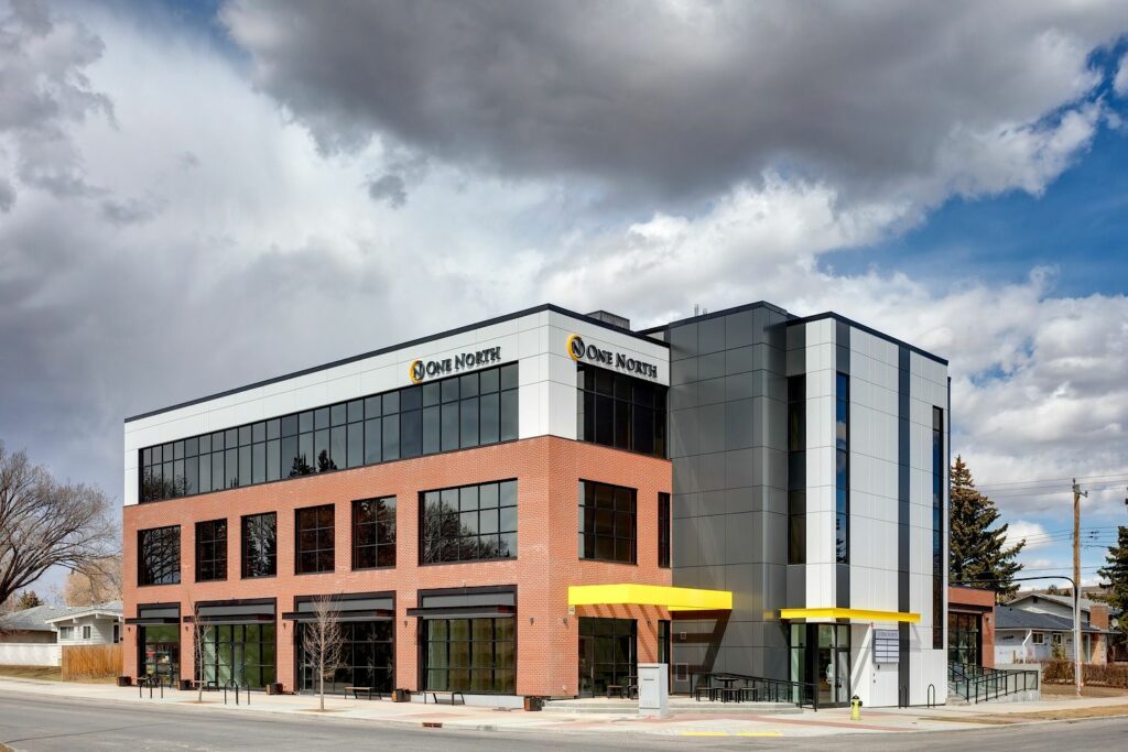
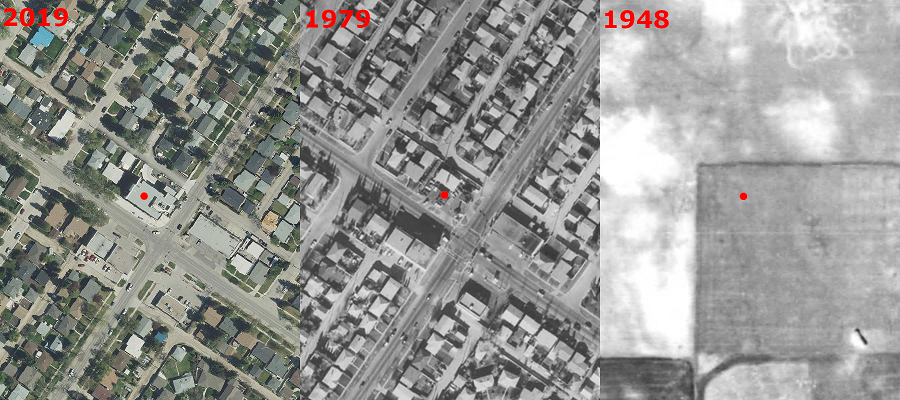
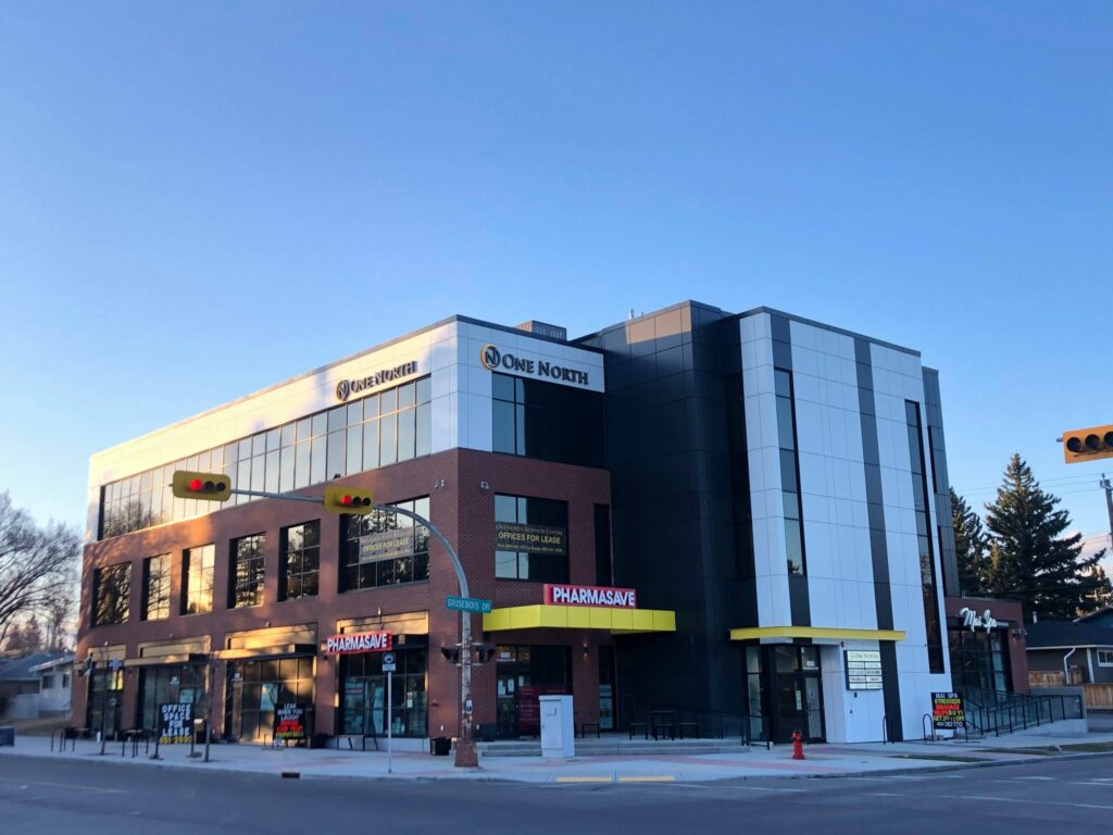
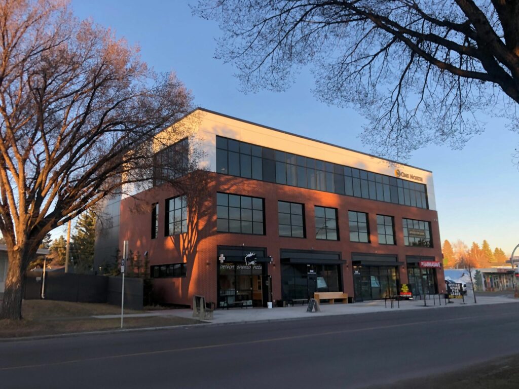
The One North Building is located in the community of Brentwood in the North-West quadrant of Calgary. It consists of three stories of mixed use commercial and retail units, two stories of underground parking, and provides commercial and retail services to the surrounding communities.
Our group designed its structural system to resist gravity and lateral loads. The One North Building went through conceptual, preliminary, and detailed design phases. Three different materials were considered during the conceptual design: wood, steel, and concrete. These materials were compared according to their cost, sustainability rating, and risk. The preliminary design of the building was completed in all three materials, allowing us to compare the alternatives. Concrete was selected for detailed design mainly due to its durability, reduction in the height of the building envelope, and increased scheduling efficiency of trades on site.
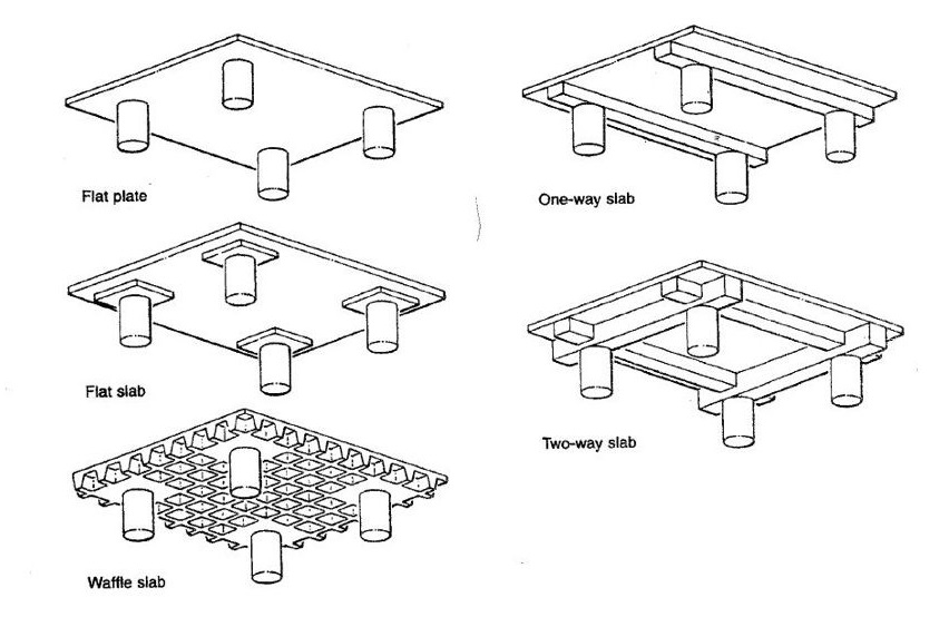
Two way flat slabs and columns were selected for the roof and floor systems, since they reduce formwork costs and give room for mechanical systems. The shear walls have been designed as an integral part of the stairwells, where they effectively resist lateral loading from all directions of the building. The foundation walls have been designed as a retaining wall in conjunction with a footing to resist sliding caused by the lateral earth pressures of soil, water and surcharge. The foundation system beneath the final parkade slab are piles, which efficiently transfer the large building loads to the soil without creating settlement issues.
[1] https://www.rentfaster.ca/ab/calgary/rentals/office-space/brentwood/332672
Meet our team members

Giuseppe Dagalea

Peter Bulger

Daniel Asfeday

Colby Fraser

Stephanie Erlendson

Shane Dorchak
Details about our design
HOW OUR DESIGN ADDRESSES PRACTICAL ISSUES
Cost was the main practical issue to overcome in our design. It was influenced by the bare cost of materials, equipment, and labour, sustainability of our building, and the degree of risk.
Base costs for different alternatives in wood, steel, and concrete were measured by developing a schedule of quantities for each design option and multiplying those quantities by a unit rate to produce the total cost. The unit rates were taken from the detailed rates in the 2012 Hanscomb’s Yardsticks, and were adjusted by the rate of inflation to dollars in 2020.
Sustainability was more difficult to measure. Our team considered sustainability from a Lifecycle Analysis perspective. What environmental impacts would the procurement, extraction, and transportation of materials have? Do certain materials require more maintenance? What does it look like to demolish and dispose of a building made out of wood versus a building made out of concrete? These are the kinds of questions we considered.
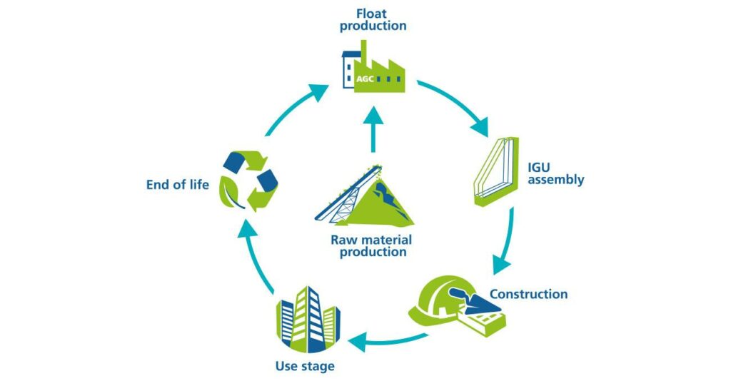
To make these qualitative questions easier to compare, we reduced them to their quantitative impact in terms of tonnes of CO2 released. This is definitely a coarse and reductive measure, but it made it sufficiently clear that wood was by far the most sustainable material, followed by steel and then concrete.
However, sustainability was only one of the criteria we judged our design alternatives on; and ultimately we went with concrete, the least sustainable of all the materials. Fortunately, even concrete can be made more sustainable, so we looked into options like substituting cement with fly ash (SCMs), and using the least amount of material possible to keep environmental impacts to a minimum.
Yet the fact that concrete is not a sustainable material continues to stare us in the face. It underlines our limits as engineers to influence the decision making process. We are the ones providing a service to decision makers, meaning we can at best put forward recommendations and nudge a client towards sustainability.
Risk was another difficult to measure criteria. We want to reduce engineering risks to ensure the building is safe and stable; and we want to reduce project management risks to keep cost low and the client satisfied. Since risks affect the cost of a material choice, we decided to calculate risk as a percentage of the alternative’s price.
Based on these criteria we selected concrete. Concrete has a built-in fire rating, which eliminates the need for additional fireproofing. It is also durable, which is an advantage in the substructure for the parkade. Concrete is available locally; whereas steel imported from the US is at risk of carrying tariffs, which may increase the price. Furthermore, wood and steel are both discontinuous with the shear walls and the substructure, leading to problems with connections, and having multiple trades on site at once. Wood and steel also yield a taller building height than concrete, meaning elevated costs for cladding. For these reasons, concrete recommended itself as the material best suited to addressing practical issues.
[1] https://www.agc-glass.eu/en/sustainability/environmental-footprint/epd-life-cycle-analysis
WHAT MAKES OUR DESIGN INNOVATIVE
At first glance, concrete design offers little room for innovation. Various standards and codes set forth procedures and methods for implementing a design, constraining our freedom of design to a large degree. That freedom was further constrained by the need for the structural system to conform with the architectural drawings, and to the norms behind the client’s expectations. However, we were still able to innovate on parts of the design.
We innovated in our design through the way we transferred loads in our structure. For example, by transferring the parkade loads to the foundation wall instead of exterior columns, it adds resistive force that prevents movement due to lateral earth pressure. Other simple changes in load paths further helped us to save cost in our design, and also eliminated the need for extra load transfer elements. For example, our team decided to continue the columns from the superstructure to the bottom of the excavation, instead of building them on top of the foundation wall. This eliminated the need for extra structural elements like corbels to help with moment and shear transfer.
Another place structural innovation affected our cost was in the use of the flat plate and column system. This system eliminates the need for beams, allowing us to save space and make mechanical placement (like HVAC ducts) much easier. It also reduced excavation costs and building height since our ceiling widths only consist of the 300 to 400 mm thick slabs. So, while it is true concrete design is a mostly standard process, the way we transfer the buildings loads is our proud feat of structural innovation.
We also innovated in our group structure. In contrast to the traditional team which has a hierarchy and established roles, our team featured shared leadership and fluid roles. Although Shane served as the Project Manager, in practice he acted more as a facilitator, allowing all group members to participate in leadership activities such as delegating work, setting deadlines, and deciding on a design direction. Furthermore, our team members crossed between their areas of expertise, with people working on columns helping those working on loading when needed. Our flat and flexible structure allowed us to play to our strengths and absorb shocks. It also encouraged and made room for innovative ideas to be expressed by individual members on equal standing with each other.
Most of these innovations were the spreadsheets used in various parts of the design. We cannot change the method of concrete design; but we can streamline it. This we did for the columns and the slabs, since they repeat every floor with minimal variation. Our spreadsheets allowed us to design these elements quickly and efficiently after the first iteration.
We further innovated by seeing our deliverables as active tools to build the future, rather than passive records to crystalize the past. For example, every draft of our brief was also a space where our group could meet with the stakeholders and seek their input in an effective and efficient manner. We worked on the brief in an iterative process, presenting parts of it to our advisors so they could provide input and feedback on a tangible piece of communication. This reduced risks and uncertainties while also ensuring our stakeholders got the product they wanted.
WHAT MAKES OUR DESIGN SOLUTION EFFECTIVE
Our design uses concrete throughout the structural system. Concrete first gained a foothold as the most effective material when we considered the substructure. It was well suited to the foundation walls and slabs because of its corrosion resistance and durability.
We chose the most effective material by considering steel, wood, and concrete for the superstructure design. Although steel and wood perform better in terms of sustainability and cost, concrete came ahead because of its durability, corrosion resistance, and continuity with the concrete substructure. This continuity reduces engineering risk by eliminating the need to design connections between different materials, and reduces project management risk by ensuring there is minimal trades (concrete and rebar) on site to coordinate.
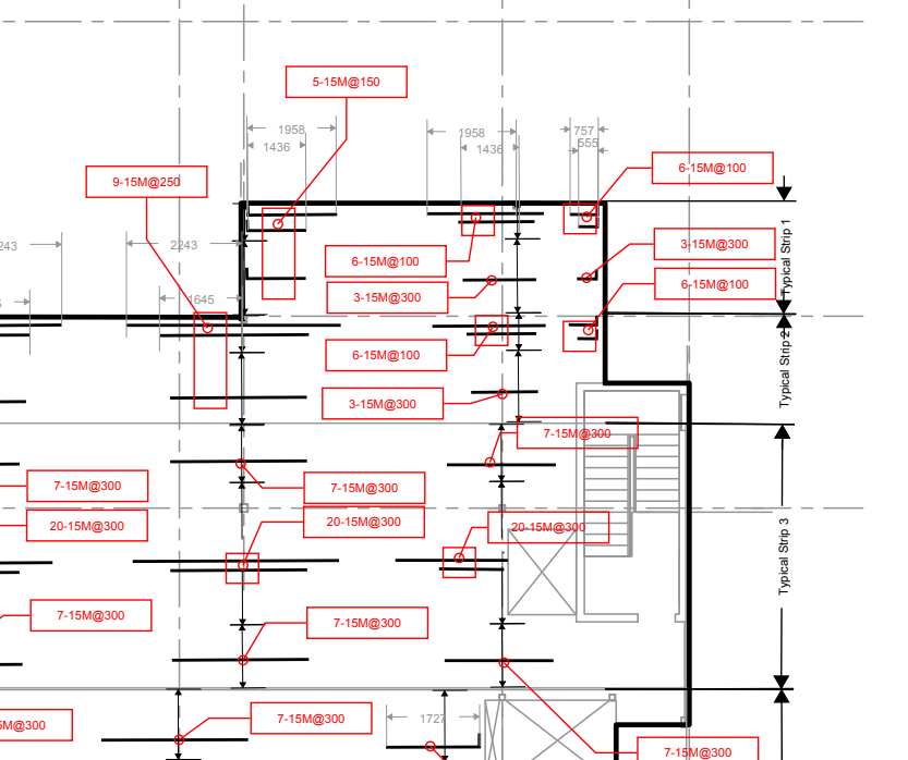
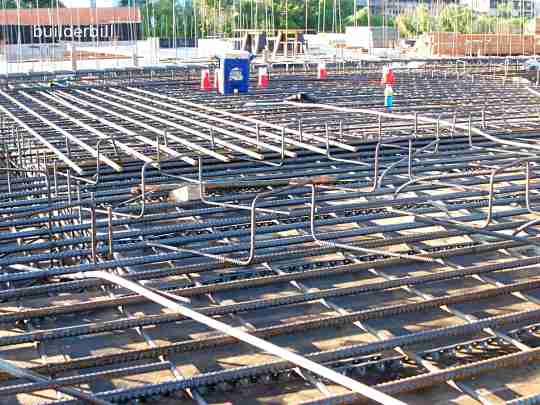
With concrete selected, we moved into the detailed design. We designed the Roof, Main Floor, Floor 2, and Floor 3 as 300mm thick two way reinforced concrete flat plate slabs. Flat plates are floors made out of concrete having a uniform thickness, which are easy to construct, and provide room for mechanical systems such as air ducts and plumbing.
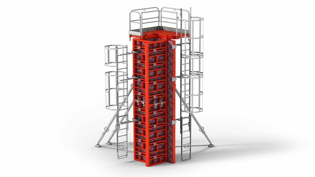
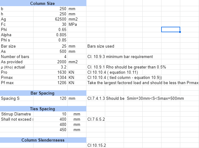
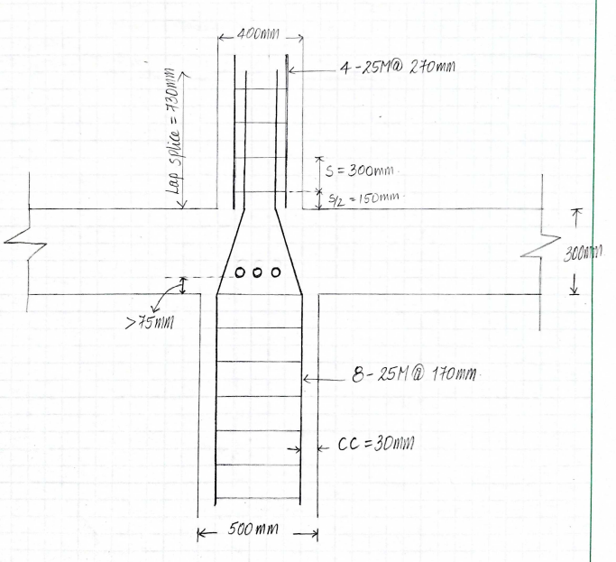
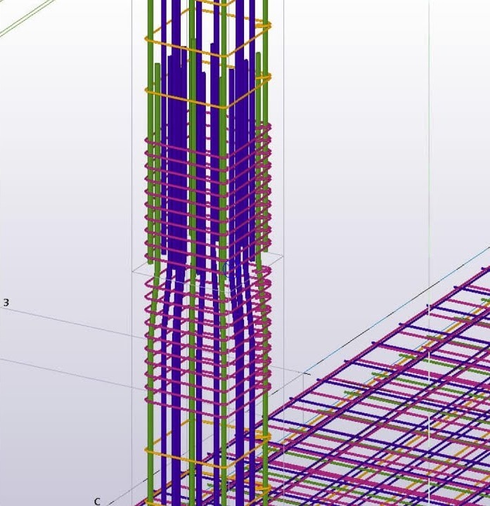
These horizontal plates allow the gravity loads on the building to flow into concrete columns. To most effectively transfer the load, we designed each column by location and floor to keep the material costs low. The size can be changed easily thanks to steel forms that are commonly available to quickly form columns in a number of sizes, and are shown below:
The gravity force resisting system for the suspended parking floor consists of a 400mm thick two way reinforced concrete flat plate slab supported on reinforced concrete columns. The greater slab thickness was required to bridge the longer spans in the parkade, as we needed to keep the area free of columns to provide room for vehicles to maneuver. A slab on grade is provided at the lowest level of the parkade, which is a concrete slab poured on the ground below.
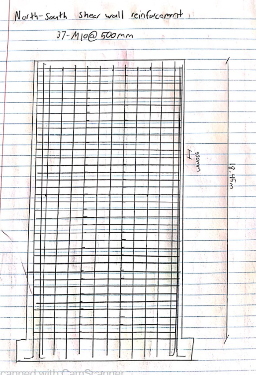
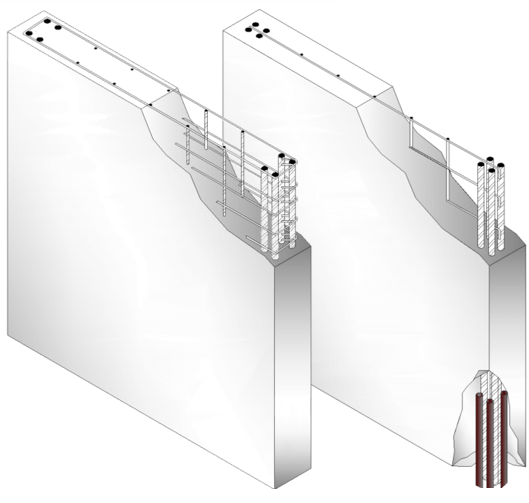
While the slabs and columns are transmitting the gravity loads, the shear walls are transmitting the lateral loads from wind and seismic forces. We chose to design the shear walls integrally with the stairwells in order to double up on function and reduce costs. These stairwells are located on the sides of the building, which allows the shear walls to provide the greatest resistance against torque forces.
The columns and shear walls ultimately transmit their load through piles into the ground. These piles were designed to be one size and depth, and the loading below each column is dealt with by changing the number of piles. We chose friction piles because the geotechnical report recommended them, and they are preferable to mat foundations because of the low bearing capacity of the soil.
[1] https://www.peri.ca/products/formwork/column-formwork/trio-column-formwork.html
HOW WE VALIDATED OUR DESIGN SOLUTION
Our design solution was validated through several different methods, which are listed below in descending order of reliance:
- Applicable codes
- National Building Code of Canada
- Canadian Standards Association A23.3-04: Design of Concrete Structures
- Application of these codes through in-house excel sheets and hand calculations
- Discussions with advisors
- Reliance on our own academic and industry experience
- S-Frame, a structural design software.
Applying the applicable codes can be tedious, so we widely employed spreadsheets to help streamline calculations. This proved especially beneficial for slab and column design, where the repetitive nature of the design meant the spreadsheet paid dividends on every iteration after the first.
We also checked our designs through the analysis software SAP, which was especially useful for specifying the reinforcement in the columns. We also drew on the knowledge of our mentors, as well as our own academic and industry knowledge. Most of us have encountered structures like the One North Building through assignments and internship experience, providing us with a quick way to make sure we were on track.
FEASIBILITY OF OUR DESIGN SOLUTION
The feasibility of our design solutions increased along with the solution itself. Our first step was choosing the most effective material out of concrete, wood, and steel. Choosing concrete gave us a material we could trust for its durability and corrosion resistance, and which kept engineering and project management risks to a minimum.
Having chosen concrete, we conducted iterative design in this material. Iterative design allowed us to size the building elements progressively closer towards an optimum between cost and strength. We ultimately selected a system of flat plate slabs, columns of varying sizes, combined shear walls and stairwells, and friction files to transmit the load.
All these elements are typical of structures like the One North Building. Furthermore, the labour, materials, and equipment for a building like the one we designed are readily available in Calgary, making it a feasible design to implement.
Partners and mentors
We would like to thank the many people who helped us with this project. Our academic advisor Dr. Neil Duncan from the University of Calgary and our industry advisor Adrian Todeila from NORR guided us through the process with patience and great advice. Additionally, we would also like to extend our gratitude to Saeed Bamasood from NORR for generously preparing a lecture for us on wood design.
Our photo gallery
http://www.ocm-inc.com/view.asp?id=71&productid=241

https://www.fprimec.com/performance-of-reinforced-concrete-shear-walls/
http://www.builderbill-diy-help.com/reinforced-concrete.html
https://www.youtube.com/watch?v=S9eVHSDgFP4
