Project Category: Civil
Join our presentation
View our presentation and join us for a Q&A session on zoom
Join the zoom link here:
https://us02web.zoom.us/j/2747586292?pwd=bnpiQUppNUVKVVpmNkxSZnA2akhIQT09
Meeting ID: 274 758 6292
Passcode: zUss3C
If you cannot access the link, please email me and I will respond promptly.
kobedaniel.malagueno@ucalgary.ca
About our project
The main purpose of Sunrise Timber Design is to assess the feasibility of using timber products as the main structural component of a large-scale building. The standard in construction for the past millennia has been to use concrete and steel as main materials for office buildings. While this practice is popular in North America, a shift to the use of timber as the primary material has been researched. This trend directly relates to the overall shift in today’s concerns regarding climate change and sustainability. In terms of energy, timber requires much less to produce than its concrete and steel counterparts, respectively demanding 4 and 60 times the amount of energy as timber, per ton produced. Moreover, as a long-term solution, timber is a renewable resource that can reduce carbon dioxide accumulation through carbon capture.
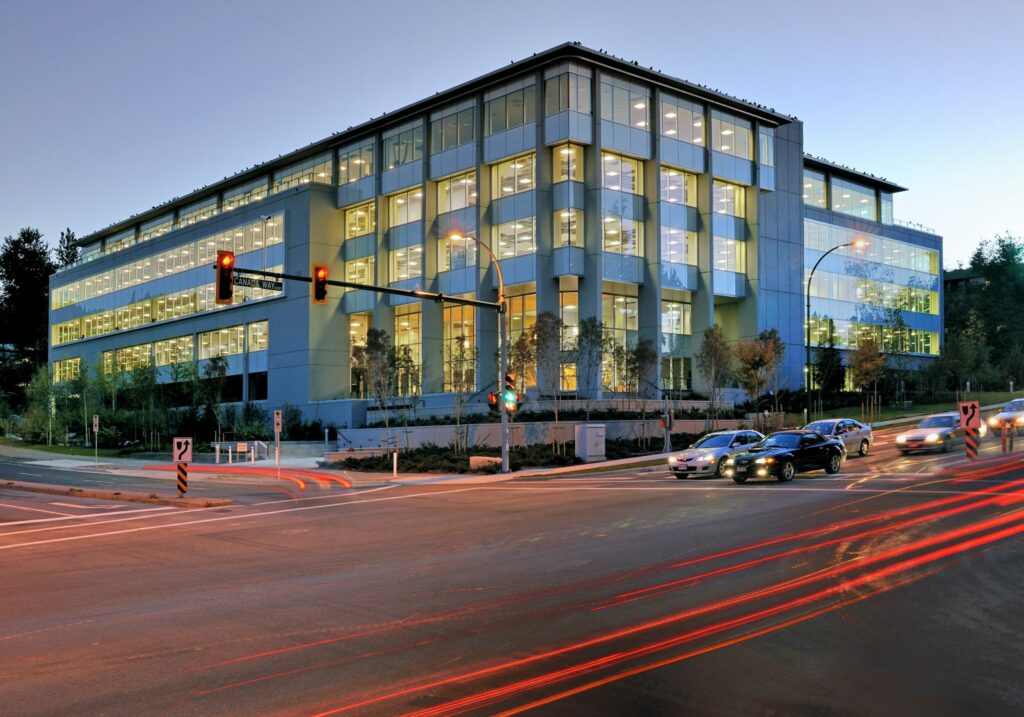
Our design goal is to redesign the already existing Building 12 in Burnaby, B.C, which is at 72 000 sq. ft and 5 storeys high while maintaining its original structural layout. The focus is to keep the original open concept and the other structural components such as cores, stairs, and envelope using mainly timber. This design project only considers the structural considerations of using timber and excluding its cost. Represented below is the findings of using timber as a structural component. If you have any additional questions, join the zoom Q&A above.
Meet our team members


Details about our design
Unique Timber Products Used
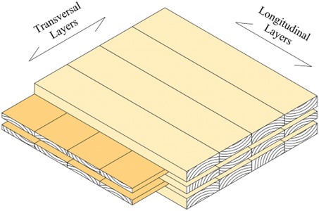
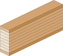
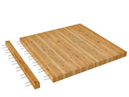
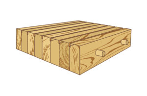
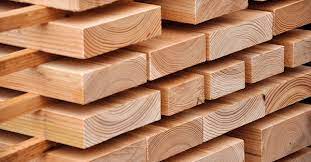
This design implements many different types of timber products such as Cross-laminated timber (CLT), Glued laminated timber (Glulam), Nail-laminated timber (NLT) and Dowel-laminated timber (DLT). CLT is stacked in perpendicular layers to compensate for the anisotropic property of wood; it was used for the exterior walls. Glulam consists of multiple layers of wood glued together and has high strength when loaded in one direction, it was used for the beams and columns. NLT consists of fastened layers using nails or screws, has high strength and is good for fire resistance, it was used for our slabs. DLT consists of fastened layers using dowels and has a high fire resistance, it was used for the cores and stairs. The following images below show each product:
Building Layout & Drawings
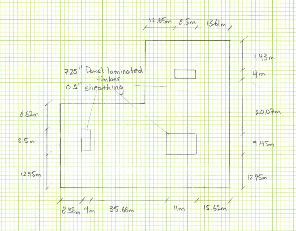
Structural drawings were created to show the layout of the building. Building 12 is L-shaped using CLT walls and glass panels as the envelope. The glass panels are present on the sections G to J and 6 to 9 facades on the 1st and 2nd floor of the building for openness and welcomes natural light. On the top and left side of the building, the two rectangles represent the staircases and the large rectangle at the bottom right represents the core, depicting the location of the elevator shaft. The black dots represent the columns of the building.
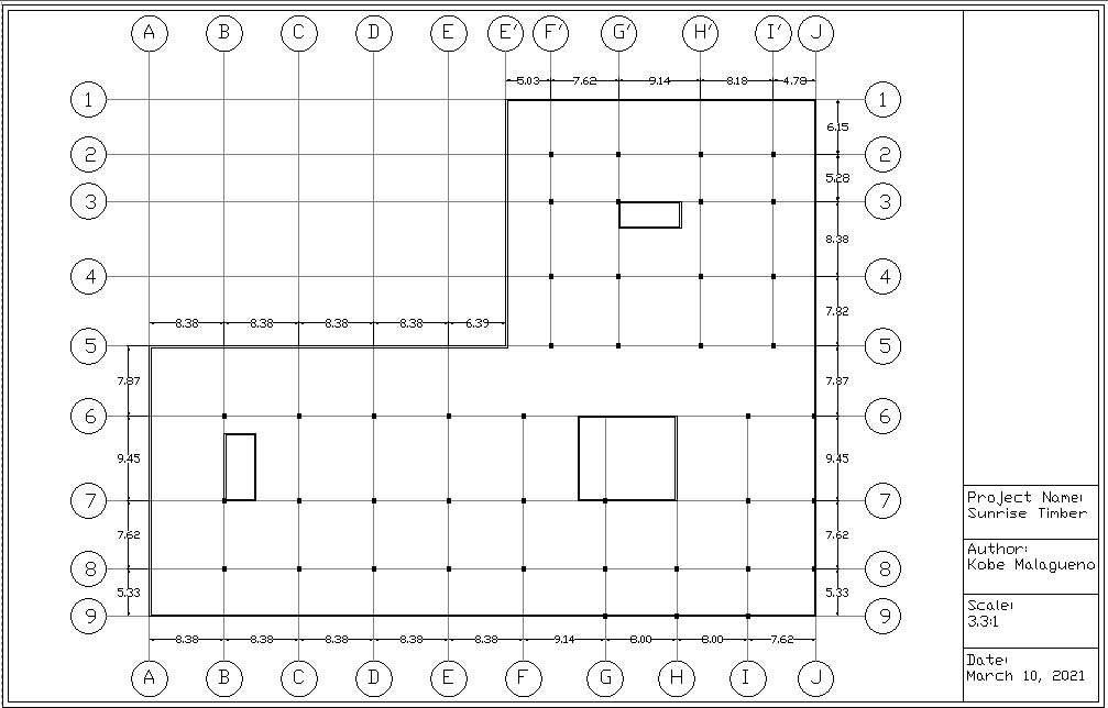
The drawing below shows a clear beam layout. The beams within the building are represented using red lines. The blue lines represent the 365×608 beams used for the largest span of 9.45m.

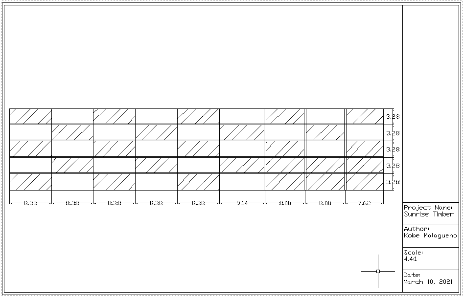
The drawing below displays the elevation view of the building from the east side. The panels with a diagonal pattern represent glass, the panels without a pattern represent CLT.
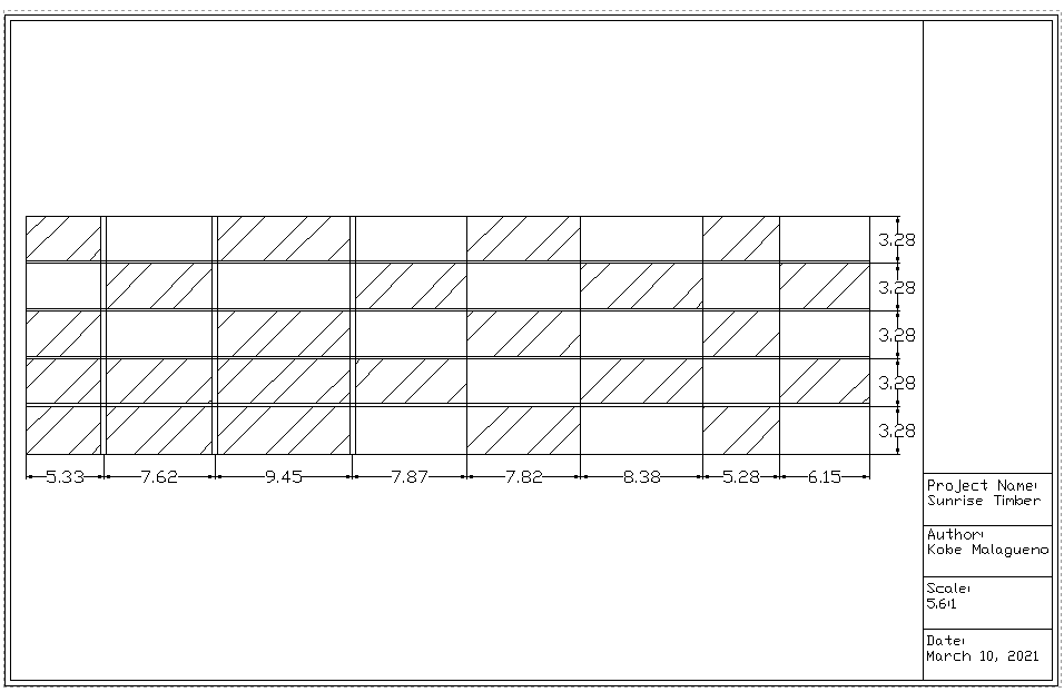
The drawing below displays the elevation view of the building from the north side. The panels with a diagonal pattern represent glass, the panels without a pattern represent CLT.
Structural Specifications
The main part of the design was to size every structural member and ensure that they were safe for use and occupancy, as well as service limit state conditions. The sizing process for each member is: consider the tributary spans affected, convert to a linear distribution, factor every load using ULS design, find maximum axial, shear, moment and deflections that are safe in accordance with the National Building Code 2019. Then, designing the section in accordance to a 90 min fire rating, highlighted by Wood Design Manual 2017. After assessing the loads and the sizes of all the members throughout the building, the values were run through the WoodWorks software to model the connections. Only the members with the maximum loads were designed and used throughout the building.
IMPORTANT: Please visit Our Photo Gallery at the bottom of the page to view the visual representation of each structural member designed. Here are the size specifications for each member:
- Slabs: Made from NLT. 140mm thickness for floors 1-5 and 184mm thickness for the roof.
- Beams: Made from Glulam. 365x608mm for the beams having a span of 9.45m, 365x532mm for the beams having a span of less than 9.45m , 265×342 for redundant beams.
- Columns: Made from Glulam. 365x456mm for floors 1 to 3, 365×342 for floors 4 and 5.
- Exterior Walls: Made from CLT. 175mm thickness throughout.
- Core and Stairs: Made for DLT. 2×8 inch panel thickness throughout.
- Connections: Made from Steel bolts. 4 different connection types specified in our photo gallery.
Challenges Using Timber
While there are advantages in using timber, it also has some challenges. These challenges have always impacted the construction industry but have a greater impact on timber designs. Therefore, additional efforts were required with respect to the following risks and challenges.
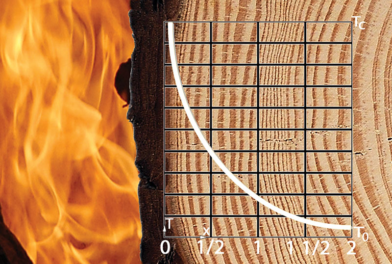
- Fire Rating: The biggest concern that arises from using timber over concrete and steel is that it does not perform as well in the case of a fire. Using the Wood Design Manual 2017, the building was adequately designed for a high fire rating of 90 minutes of fire evacuation. The common problem was that to satisfy the fire rating requirements, members had to be heavily over-designed. Smaller cross-sections could have been used for most members if fire safety protocols were not considered.
- Deflections: Since wood has a lower stiffness, it performs poorly in resisting deflections. This was particularly challenging when designing for long spans. For example, referring to the structural drawing, the span between 6 and 7 is 9.45m, which is the longest span, a 365x608mm was used. This beam is atypical and would need to be custom-made. However, for all the other beams, 365x532mm was used instead.
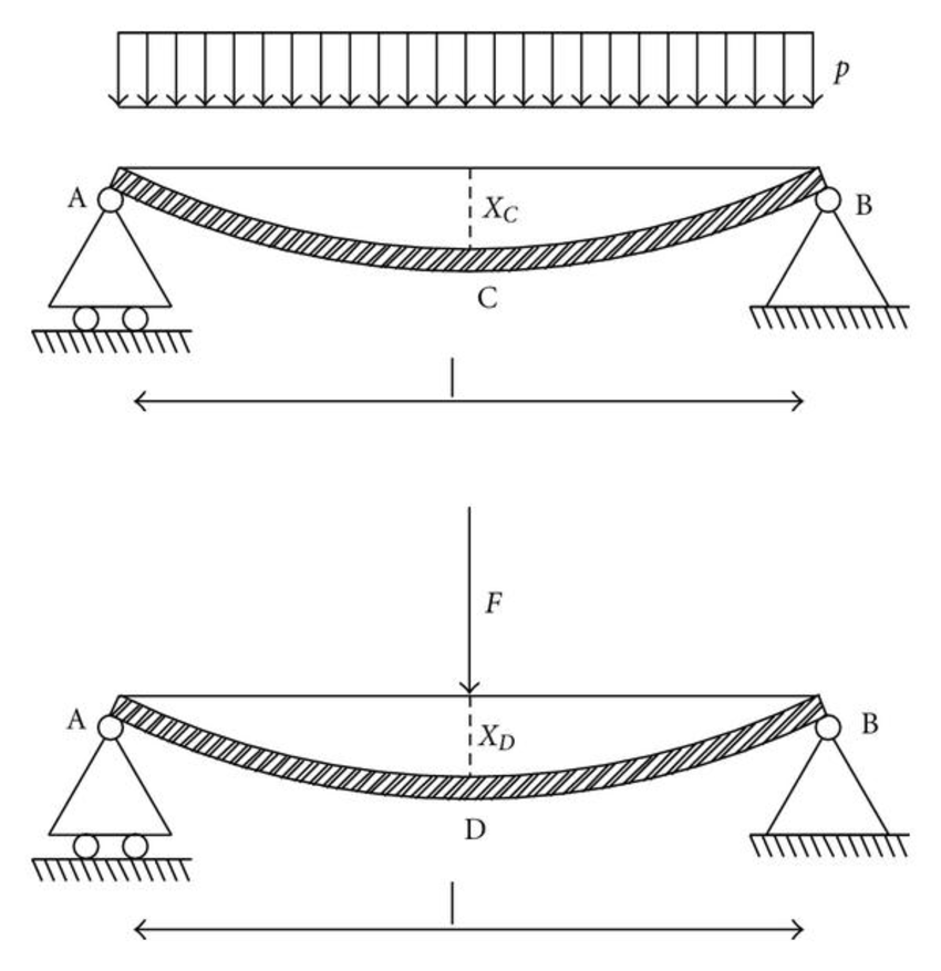
- Vibrations / Lateral Forces: The most important aspect when designing floors and beams are the vibrations, usually governing its design. To reduce the magnitude of vibrations, a thin 50mm concrete cover was added atop the slabs. A moisture barrier is added between the concrete cover and the slab to prevent moisture damage from the concrete cover. Another design challenge is lateral force resistance. Since this building is proposed to be assembled in Calgary, high wind and earthquake loads are negligible, thus, the cores are sufficient to support the lateral loads.
Alternative Methods and Iterative Processes
In the original design of Building 12, the cores were made of concrete. In the proposed concept shown in Figure 7, Nail-laminated timber (NLT) cores were proposed as a timber alternative. In the actual redesign of the building, Dowel-laminated timber (DLT) cores were used instead due to their better fire rating. As such, the thickness of the cores was reduced.
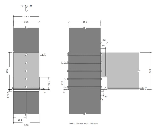
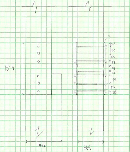
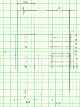
From floors 1-3 and floors 4-5, the column sizes are 365x456mm and 365x342mm, respectively. The columns are continuous for each set of floors; however, a connection was required between floors 3 and 4. It was proposed to have a steel hollow structural section (HSS) with welded plates which are then screwed into the columns, as shown in our “column to column” drawing. This is an unnecessary complex connection requiring more designing and a simpler connection can be used instead. As such, the connection is made of 3 welded steel plates which are then bolted to the column.
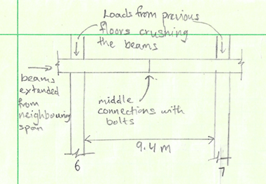
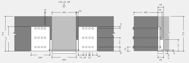
A beam with a span of 9.5m was required, however, readily available glulam beams do not meet the adequate moment resistance. As a solution, a stronger material such as a steel beam was suggested. To be consistent with the wood aesthetic, the use of a steel beam was not aesthetically engaging. As an alternative method, beams from neighboring spans were extended and connected using bolts, as shown in our “beam to beam” drawing. On the other hand, it was not a viable option with respect to the continuous columns. This is due to the beams being crushed by the columns because of the anisotropic nature of wood. Another alternative method was to have 2 separate beams going from side to side. This method would increase the resistance of the beams almost doubling its resistance. The drawback is that it would require more bolts going through the columns which would weaken the column. Therefore, the better option was to have a beam with a higher cross-sectional area which is not readily available and would require being custom made.
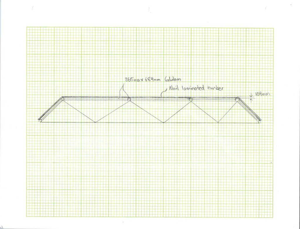
The concept requires a curved glulam roof. However, a curved glulam roof is not feasible option due to a large span and the size unavailability of any curved glulam beam. Even if, the longest curved glulam beam was used and connected using steel plates, the calculations would be too complex, and it proved as such. Therefore, the alternative option was to have the columns erected up to the roof and have the columns bear the loads leading to a roof with slanted sides instead of a curved roof as shown in our “roof truss” drawing.

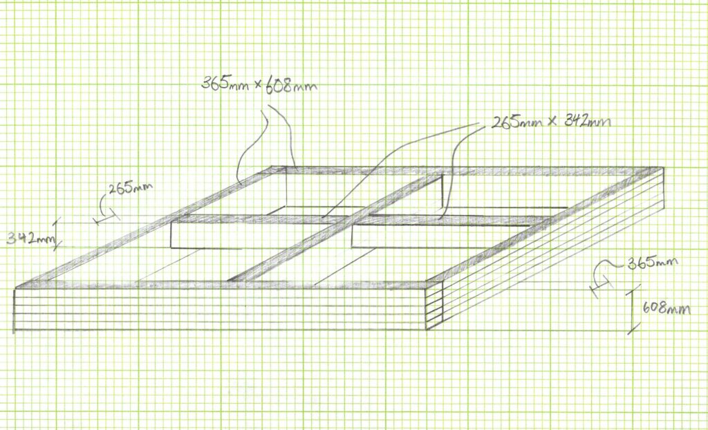
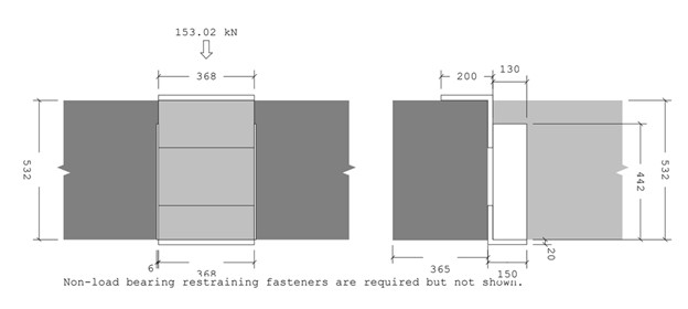
Due to the thickness of the girder, the use of bolts as a connection is inadequate since it is weakening the girder. The addition of bolts to the girder, weakens the girder causing splitting in the girder. Therefore, the solution was to use a top hanger connection, that is hanging the beam directly on top of the girder, eliminating the use of holes in the girder.
HOW OUR DESIGN ADDRESSES PRACTICAL ISSUES
The standard in construction for the past millennia has been to use concrete and steel as main materials for office buildings. However, the use of these materials brings a major concern for energy consumption and sustainability. Many countries have been politically inclined to design environmentally friendly structures for a sustainable future. This can be seen through implemented policies such as carbon tax. Since 2011, China has experimented with a cap-and-trade system, which will be implemented in the concrete and steel industries since being the country emitting the most cement-related carbon dioxide. The European Union also implemented a cap-and-trade system to reduce carbon emissions. Overall, encompassing the issue of engineering design and politics for a sustainable future.

WHAT MAKES OUR DESIGN INNOVATIVE
The use of timber in a large-scale building instead of concrete and steel is what makes this design innovative. Throughout the design process, using concrete or steel would have been an easier alternative, but the use of timber products was maintained. For instance, the use of a concrete core is common due to its high lateral forces resistance. Alternatively, DLT was used, thus, using as many structural members out of timber as possible. Through the application of innovative design, every structural member was designed using timber products as listed in the “Unique Timber Products Used” section over a hybrid solution.
WHAT MAKES OUR DESIGN SOLUTION EFFECTIVE
The effectiveness of this design is shown through timber products having the same performance as concrete and steel. As mentioned in the “Challenges With Timber” section, the main design challenges that are specific to timber are fire rating, deflections, and vibrations/lateral forces. The sizing of each structural member throughout the building was carefully assessed and chosen to provide an excellent resistance to all possible loads on the building. Structural members that can resist axial, shear, and bending while overcoming these challenges were met. The building was designed to be as safe as possible.

HOW WE VALIDATED OUR DESIGN SOLUTION
The design solutions were validated using contemporary practices of wood design and with advice from experienced engineers within the industry. The most up-to-date practices of wood design were used such as National Building Code 2019 and the Wood Design Manual 2017. After verification of the structural members using these design manuals, the WoodWorks software was used to check for the connections between members ensuring safe transfer loads throughout the system.
For constant verification, regular check in meetings were done with our academic advisor, Dr. Dann, and our industry advisor, Adam Robertson. He has specialized in wood design. Whenever there were any uncertainties, the ideas were run by him for any feedback and common practices and considerations.
FEASIBILITY OF OUR DESIGN SOLUTION
After the evaluation of all the design solutions, this design is very feasible. Timber structures are already popular in countries such as Norway, Japan, and Sweden. These countries have discovered many ways to successfully use mass timber structures for all types of buildings such as convention centers, schools, stadiums, and large offices – directly relating to this project. The goal now is to get the push to start using timber in North America. As highlighted previously, concrete and steel are the main components in North American buildings. According to this Capstone project, there are many practical advantages to using timber for large-scale buildings that are feasible.

Partners and mentors
We are grateful to everyone who made this project a success. Our academic advisor, Dr. Dann who met and encouraged us on a weekly basis for this capstone project. Our industry advisor, Adam Robertson who guided us with his knowledge of timber design, teaching us about the many design considerations. Our course coordinators Jacob Lamb and Neil Duncan, who provided an excellent framework helping us learn and succeed throughout our Capstone project.
Our photo gallery