Project Category: Civil
Join Our Presentation
About Our Project
Vivo for Healthier Generations, formerly Cardel Place, is a recreational centre located in northeast Calgary. The facility is currently undergoing a $65M expansion project. Vivo will be expanded to include an indoor park, a six-lane 56-meter lap pool, an expanded fitness centre, and other facilities. The goal of the expansion project is to increase Vivo’s capacity to “raise healthier generations in Calgary and beyond.”
The objective of the indoor park is to provide year-round access to community greenspace, even during harsh Calgarian winters. Having recognized the utility of this concept, our team’s focus was directed to the structural design of the indoor park. The scope of our design included the following structural components within the indoor park:
- Roof framing, primarily considering a steel truss system
- Interior and exterior columns
- Lateral load resistance system
- Connections between structural members
- Concrete foundation design, primarily considering foundation piles, pile caps, and grade beams
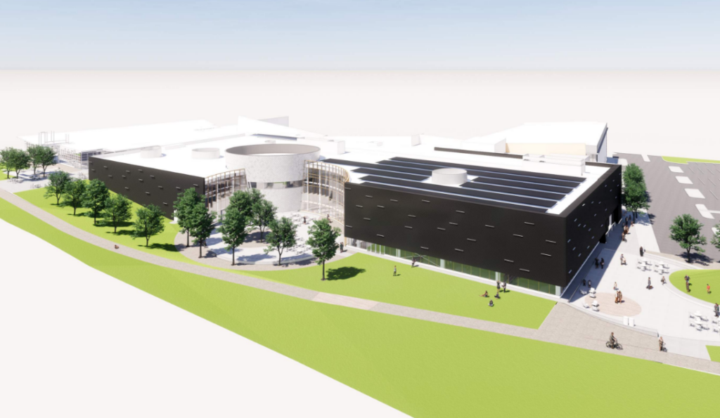
Courtesy of DIALOG
The objective of our design was to meet the structural requirements in an efficient and sustainable way without undermining the utility of the indoor park.
Meet Our Team Members


Details About Our Design
HOW OUR DESIGN ADDRESSES PRACTICAL ISSUES
The most prevalent structural challenge within the indoor park was the ~70m x ~33m unsupported span, as shown in Figure 2. In order to preserve the functionality of the park, there were no interior columns to serve as intermediate supports for the roof span. Given that the roof needed to span ~70m x ~33m, it was crucial to develop a strong yet lightweight roofing system. Though we initially aimed to implement relatively light steel W-beams, we ultimately designed a Warren Truss (Figure 3). Using Warren Trusses running N-S, the critical loading conditions were supported while maintaining allowable deflections.

Original drawing courtesy of DIALOG
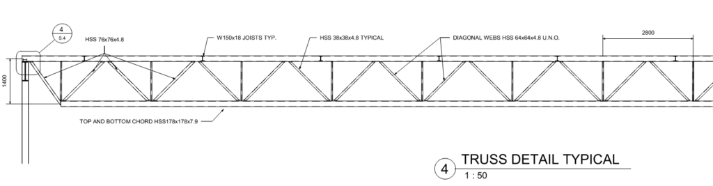
In order to preserve the natural feel of the indoor park, the architects planned for a large skylight to provide natural light. As shown in Figure 2, the skylight disrupts the uniform distribution of trusses and purlins. The spacing of the members was adjusted to avoid having members running directly under the skylight and casting a shadow over the park.
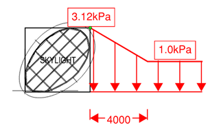
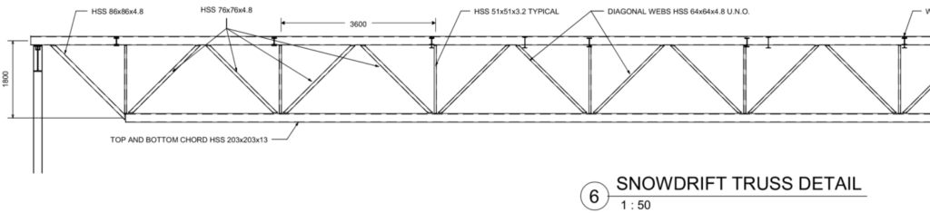
More importantly, the raised skylight creates the potential for snow drifts to form around it. The snow drift magnitude was calculated in accordance with the National Building Code (Figure 4). Further, the snow drift was considered in four directions as shown in Figure 5. The standard truss (Figure 3) was not structurally sufficient in areas where snow drifts may form. Figure 6 displays the larger trusses designed for the critical regions.

WHAT MAKES OUR DESIGN INNOVATIVE
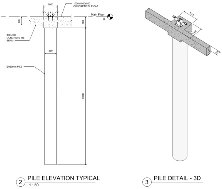
One unique goal of expansion projects is limiting interruptions to the existing building during construction. Due to the proximity to Notre Dame High School and the existing Vivo facility, the foundations team determined that less common Continuous Flight Auger (CFA) piles were best suited for the job. CFA piles produce less noise and vibration when compared to more common piling techniques. The foundations team relied on the information provided in the geotechnical report to verify the compatibility of CFA piles with the site’s soil conditions. Figure 5 displays the piles designed by the foundations team. Figure 8 illustrates the installation process of a CFA pile.
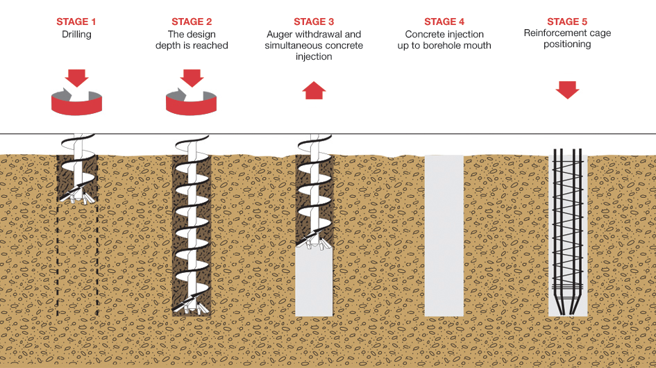
Courtesy of El-Gindy Contracting
Considering that the indoor park’s roof is flat, another practical issue is the potential for rain ponding. Due to the large area of the roof, there can be a considerable amount of water collected on the roof during a rainstorm. Our design team assumed that all drainage was clogged/non-functional in order to assess the impacts of ponding. Should the ponding occur at the roof’s midspan—where deflections are largest—there is a high potential for catastrophic failure. This issue called for innovation in the design process, so the roof was ‘warped’ to direct rain to a favorable location. As shown in Figure 9, two differing slopes were used to direct the pond to the perimeter of the building. Design checks confirmed that the structural members could sufficiently support any potential ponding in the location shown.
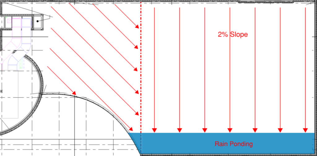
Original drawing courtesy of DIALOG
WHAT MAKES OUR DESIGN SOLUTION EFFECTIVE
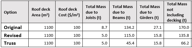
As stated, the design of the indoor park roof was initially completed using steel W-beams (Revised, Table 1). Pivoting to the use of Warren Trusses (Truss, Table 1) allowed us to satisfy the structural requirements while saving roughly 69.6 tonnes of steel (Table 1). In addition to the material savings, the implementation of Warren Trusses will better serve the objectives of the indoor park. Replacing large steel W-beams with Warren Trusses will allow for a more ‘open feel.’ Most importantly, natural light entering the park through the skylight will have a much wider reach thanks to the large openings within the truss.
Achieving structural stability—while limiting costs and environmental externalities—is the hallmark of an effective structural design.
HOW WE VALIDATED OUR DESIGN SOLUTION
The following codes were used to inform our design process:
- National Building Code of Canada 2015 (NBC 2015)
- CSA O86 Engineering Design in Wood 2014
- CSA S16 Design of Steel Structures 2019
Our design teams built Microsoft Excel spreadsheets in order to support an iterative and everchanging design process. As conditions and considerations changed, the results of our calculations could be updated easily.
In order to validate the results of our calculations, we relied on the assistance of our Industry Advisor, Mr. Ralph Hildenbrandt. Thanks to Mr. Hildenbrandt’s wealth of experience in structural engineering, he was able to review our work and identify issues.
FEASIBILITY OF OUR DESIGN SOLUTION
During the early stages of the project, our team designed multiple preliminary designs that made use of different materials and layouts. We selected a preliminary design to further develop based on the following criteria: Cost, sustainability, and constructability. The steel framing system described above was the design that best satisfied the aforementioned criteria. As stated, replacing the solid W-beams with Warren Trusses directly benefited the design in terms of cost and sustainability. Regarding constructability, welds were implemented in the connection design wherever possible to minimize the amount of on-site fabrication required. By identifying the guiding design criteria—especially constructability—in the early stages of our project, we were able to ensure that the final product was feasible.
Furthermore, the feasibility of the design was preserved by the formulaic nature of structural design. As a team, we drew inspiration from similar structures. For example, the interface between the trusses and the girders was inspired by the roof layout at Westside Recreational Centre. By designing elements of the structure based on similar buildings, we affirmed the feasibility of our own design.
DRAWING SET
POSTER
Partners and Mentors
Our success as a team would not have been possible without the guidance of our industry and academic advisors. Mr. Ralph Hildenbrandt of DIALOG frequently challenged us to step outside of our comfort zone. That said, he always made himself available to guide us through new concepts. Dr. Neil Duncan was a constant source of positive affirmation. Dr. Duncan kept us on track and constantly reminded us that we were doing a great job.
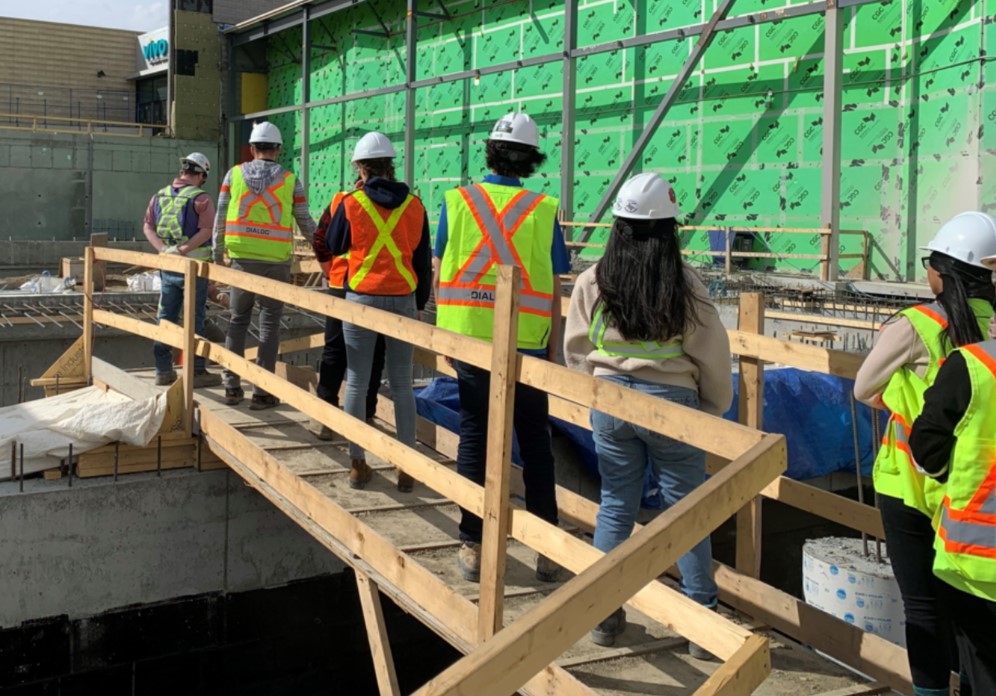
Additionally, we would like to thank Dr. Ron Chik-Kwong Wong for guiding the foundations team throughout the duration of the project. Another thank-you to Dr. Mamdouh El-Badry for offering support to our structures team. We also owe a big thank-you to Mr. David Pesta of DIALOG for taking the time to guide us through a comprehensive site tour. Finally, a thank-you to Jacqueline Vera for her effort to keep the project fun and engaging.
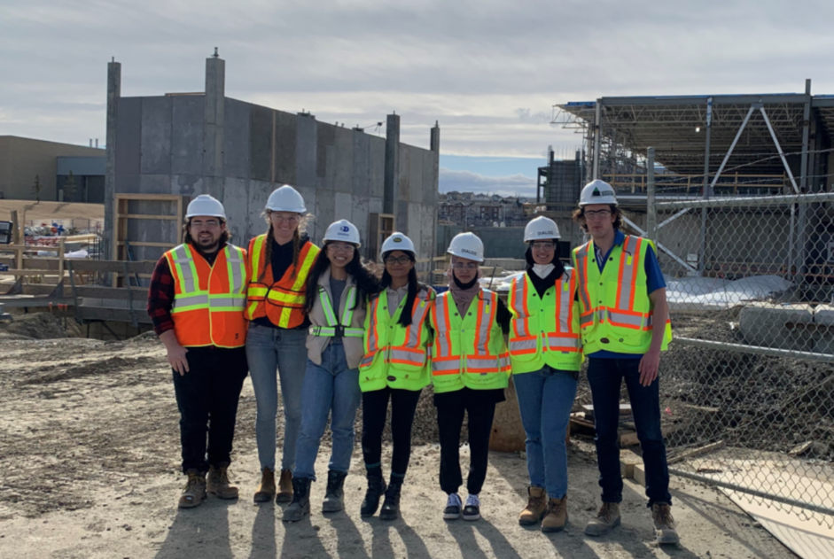
Our Photo Gallery