Project Category: Electrical
Join Our Presentation
About Our Project
Background Problem
Our sponsor SKF currently offers G5 Magnetic Bearing Controllers that are used in specialized motor control systems. As demand for these systems increases, it has become apparent that their current approach of manually testing each controller is a bottleneck for their productivity. Each fully assembled controller requires 16 hours of manual testing by production staff and any non-conformance requires additional investigation time. In preparation for projected demand, SKF wishes to transition to a more automated, reliable, and efficient way of validating their controllers.
Our Solution
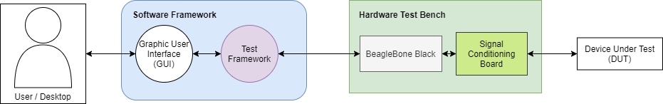
Our team designed a solution that includes a software framework for the automation of circuit card validation. We used our framework to validate the G5 BNC Circuit Card with a custom hardware interface that we built. The test framework is responsible for defining specific tests, communicating those tests to the hardware interface, and processing the results sent back. Our design modules are highly extensible and equip SKF with the means to automate their G5 Controller circuit card testing far beyond just the BNC Card.

Our Team Members

(Hardware Design)


(Hardware Design)

(Project Manager)

(Software Design)

(Software Design)

Details About Our Design
SKF uses a thorough manual testing procedure to ensure their controllers meet high performance and quality standards expected by their customers. However, manually testing each controller takes significant time and effort. Here are the primary issues that can result from manual validation of the controller at a system level:
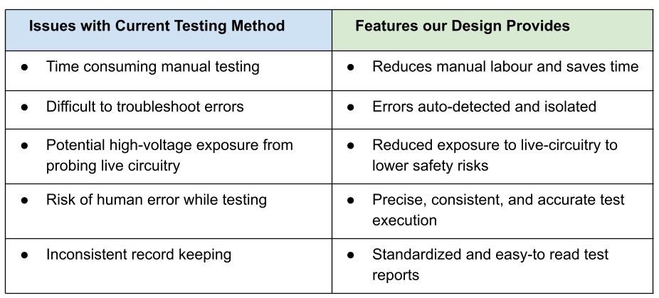
Our modular design provides a versatile product that solves the issues presented by manual testing, outlined by the diagram below. We used our design to validate the BNC Front Panel circuit card in the G5 Controller, and also designed the system to be easily extendable for other circuit cards.
With our software framework and custom hardware interface, we are able to automate testing of the following aspects of the BNC Front Panel circuit card:
- Digital logic of 19 inputs and outputs on the circuit card
- Termination resistance on 4 input BNC connectors
- I2C communication to enable and disable termination resistors
- I2C communication that controls switches and digital logic
- Current and power draw
HOW OUR DESIGN ADDRESSES PRACTICAL ISSUES
Here is how our design addresses the issues presented by manually testing the BNC Front Panel circuit card:
- Sends automated tests through the test bench using custom test framework, reducing manual labour and saving time
- Detects circuit card failures before full system assembly saving many hours of troubleshooting and repairs
- Minimizes interactions between the user and live circuitry, decreasing potential exposure to high voltages
- Produces reliable and reproducible results with highly accurate automated testing
- Makes test setup and monitoring intuitive using a graphical user interface
- Automatically generates test reports and organizes results
- Allows the user to test other devices in the future with custom tests which can be easily defined and modified
WHAT MAKES OUR DESIGN INNOVATIVE
Software:
- Utilized Robot Framework test automation libraries to create reusable testing software extendable to any circuit card
- Designed to be human readable and intuitive
- Allows straightforward definition of new tests and manipulation of existing tests
- Integrated manual tests (such as visual checks) with automated tests for flexibility
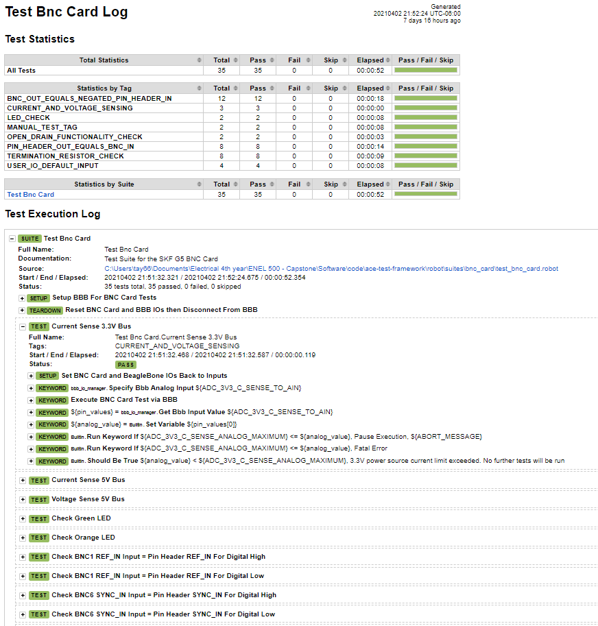
- Implemented an automated excel test result report generator
- Modular software design that allows for smart code reuse, and easy parallelization of work between the Test Framework and the BeagleBone server
- Low dependency between test framework tests and hardware
- Requests tests from the server in a JSON format
- Server runs test and sends the results as a JSON
- Provided a simple interface for production staff to enter test metadata, start tests, and monitor tests
- Checked for proper signal definition using a programmatic suite validator
Hardware:
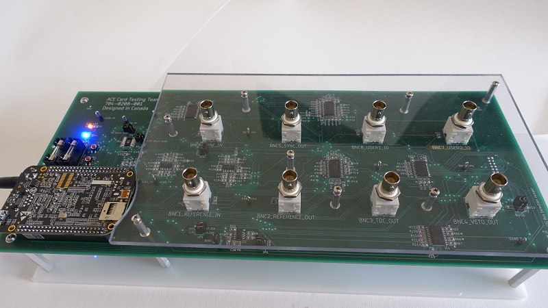
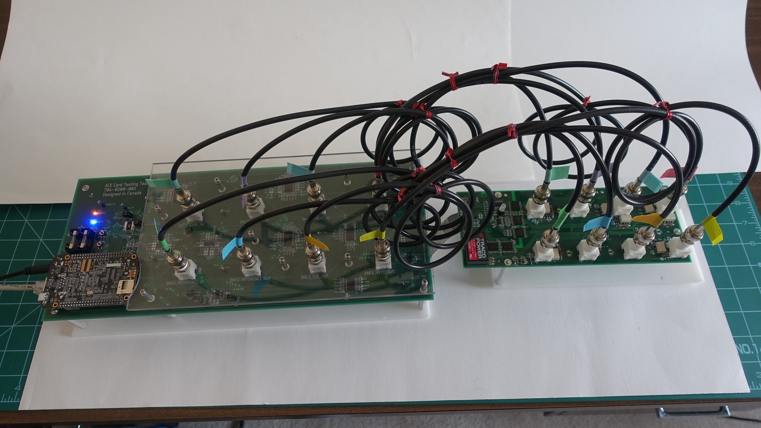
- Designed custom PCB for the hardware interface to condition the signals to be compatible with the BNC Card

- Utilized the BeagleBone Black development board as the core module of the board to handle computer to hardware communication
- Substantial number of pins available for digital and analog signal definition
- Accommodates communication with additional external peripherals if needed
- Reusable for design of future hardware interfaces
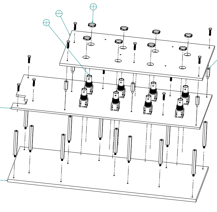
- Designed and assembled custom mounting plates and panels for the test setup
WHAT MAKES OUR DESIGN SOLUTION EFFECTIVE
- Our framework and hardware interface will be used by SKF to validate their BNC cards during production
- The G5 controller product line only requires small batch testing which makes it suitable for test set up that contains both automated and manual aspects
- SKF will be able to further develop our design in-house, reducing external cost requirements
- The design was made iteratively with constant feedback from sponsors and testing with production staff to ensure the solution best meets SKF’s needs
- Our framework is highly abstracted and intuitive, making it easy to extend to other circuit cards
- Our design is well-documented and detailed for successful handover to SKF
HOW WE VALIDATED OUR DESIGN SOLUTION
We validated our design solution by creating detailed test plans to verify our design at each major milestone. Prior to validation, we held internal design reviews among our team, and held external reviews with our sponsor to ensure we met their requirements and schedule. Our software was tested extensively when new features were added to ensure compatibility with the system. Our hardware design was thoroughly reviewed by our sponsor, and we additionally created and executed a detailed test plan to ensure the assembled hardware functioned correctly.
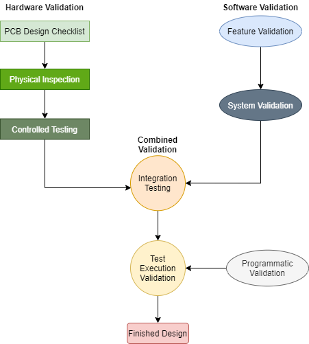
Software:
- Verified all BeagleBone input and output pins could be controlled and read via computer commands prior to any hardware integration
- Performed incremental code reviews facilitated by Git revision control to ensure code changes functioned correctly prior to system integration
- Developed programmatic validator to ensure signal definitions were correct before generating any signals on the hardware interface
Hardware:
- Created a detailed design specification to ensure all design decisions were logical and appropriate for our solution
- Validated our PCB schematic, layout, and component libraries using SKF procedures and checklists
- Verified correct component placement and values during PCB assembly, and conducted a full physical inspection after completion
- Performed continuity checks on critical signal paths to ensure correct connections
Integration Testing:
- Supplied controlled inputs to the hardware interface to validate specific signal paths
- Incrementally integrated software and hardware components to ensure no signals were misconfigured before full system validation
FEASIBILITY OF OUR DESIGN SOLUTION
Key factors that made our design solution feasible were:
- Using the existing input and output control libraries of the Beaglebone board along with peripheral control libraries
- Using hardware components that did not require complex control signals
- Prior experience with Robot Framework on the software team
- Planning and testing designs in advance of deadlines leaving extra time for refinement
- Allocating time to implement improvements on the minimum viable product allowing us to exceed design expectations
- Defining clear technical specifications for both hardware and software ensuring that all stakeholder expectations were met
- Limiting the scope of our design to test a single unique circuit card creating more time for our software framework
- Regular support and feedback of 2 senior electrical engineers from SKF
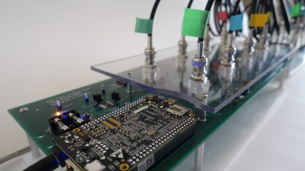
Photo Gallery
Signal Conditioning Board 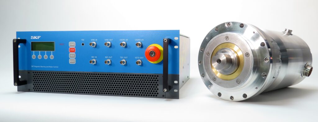
SKF G5 Controller and Motor 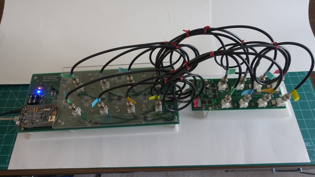
Signal Conditioning Board (left) Interfacing
with BNC Card (right)
Partners and Mentors
The success of our project would not have been possible without the support of others outside of our team. Our sponsor SKF was critical to our success as a team and we would like to acknowledge Greg Smith and Udell So for the dedication of their valuable time and consistently offering their expertise. We are incredibly thankful to have a sponsor that was willing to work so closely with our team and offer insights and resources that were instrumental in our success. We also want to thank our faculty advisor Dr. Denis Onen for his helpful feedback and suggestions that were key considerations in our design. Special thanks to Dave Yoner from Trilogy-Net for offering to support us with our PCB. Additional thanks to Zahra Kabirkhoo and Dr. Hamid Zareipour for supporting us in this course.
