Project Category: Electrical
Join our presentation
About our project
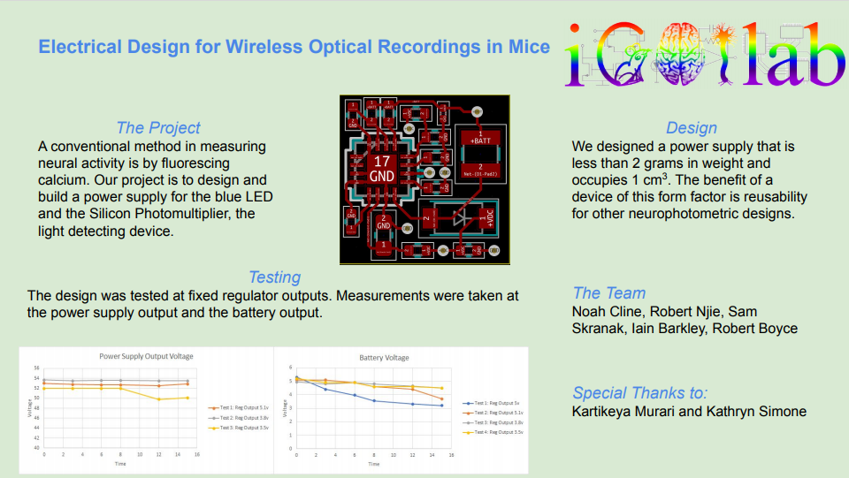
Fiber photometry is a method used in neuroscience research that uses calcium imaging to detect neural activity. It primarily used to record the neural activity of deep brain structures within freely-moving animals, such as rats and mice, by recording the fluorescence emitted from specific, experimentally relevant cells. The optical signal can then be correlated with observed natural behavior to discern possible roles the targeted neural population may contribute in orchestrating complex behavioral sequences. Conventionally, an optical fiber relays excitation and emission light from the animal’s neural tissue to an optoelectronic system on the benchtop. This technology has matured to achieve ultra-low power operation for applications that involve long-term and repeated measurements such as those related to learning and memory. However, the fiber impedes the animal’s natural motion and prevents the ability to observe naturalistic behaviors, especially those related to social phenomena. Wireless photometry systems that operate without an optical fiber have been proposed to address these challenges, but they typically require high light levels that degrade the signal over time, precluding highly valuable applications in 24-hour monitoring. The Integrated Circuits and Optical Imaging Lab at the University of Calgary have previously validated the use of a silicon photomultiplier (SiPM) as a suitable photodetector for this purpose. The animal’s size and weight further constrains the dimensions of the wireless photometry systems to prevent encumbering the animal.
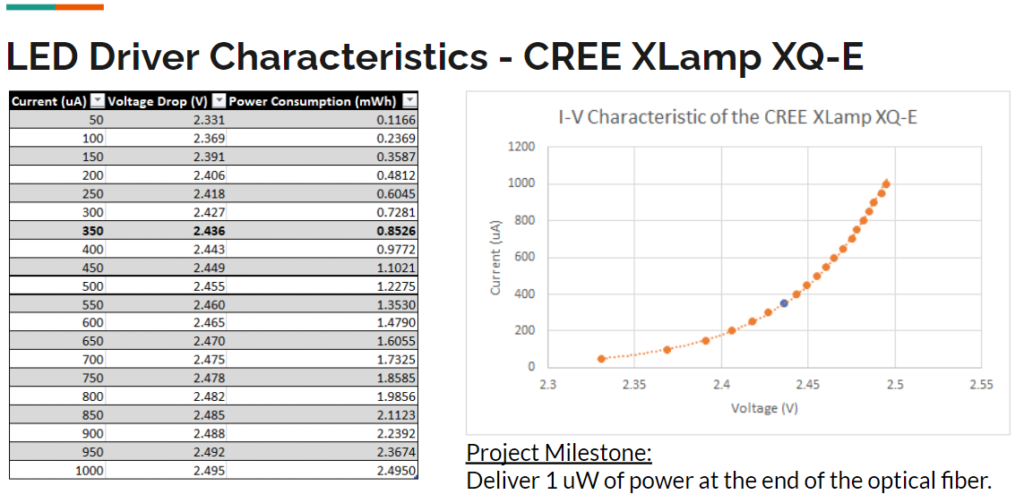
The objective of this project is to complete and validate the electrical design on a PCB for an ultra-low power wireless photometry system that can power a SiPM and an LED driver for 1 hour, weigh less than 1 gram, and be smaller than 1 cubic centimeter, While outside the scope of the capstone, the system will incorporate a PIC microprocessor to control the device’s operations, and all modules will eventually be integrated together on a miniaturized PCB. Finally, and with time permitting, we will design and validate a suitable low-noise analog front-end amplification circuit making use of a coherent detection technique for best signal integrity (i.e. analog or digital lock-in amplification), capable of delivering 1 uW of excitation power and detecting 0.5-1 pW of received optical power, both in the visible spectrum (465 nm +/- 20 nm excitation, 525 nm +/- 25 nm emission).
Meet our team members


Details about our design
HOW OUR DESIGN ADDRESSES PRACTICAL ISSUES
Our design is trying to solve the issue of a small form factor power supply that is able to power a silicon photomultiplier, which is a sensitive photodetector that needs an operating voltage of 60 Volts. Since lithium ion battery cells have the highest energy density/gm out of any commercially available battery, we have decided to use a coin cell battery with a nominal operating voltage of 3 Volts. Our power supply is designed step 3 Volts to 60 Volts for one hour with a PCB design that is no larger than 1 cubic centimeter and weighs no more than one gram.
WHAT MAKES OUR DESIGN INNOVATIVE
Power supplies are tricky to work with and the innovation comes in the form of creating a power supply that is able to meet our very specific needs. Since the device will be mounted on a mouse, the size and weight constraints the space of practical solutions. Our solution is the most innovative because it has the highest output input voltage ratio for its weight and size.
WHAT MAKES OUR DESIGN SOLUTION EFFECTIVE
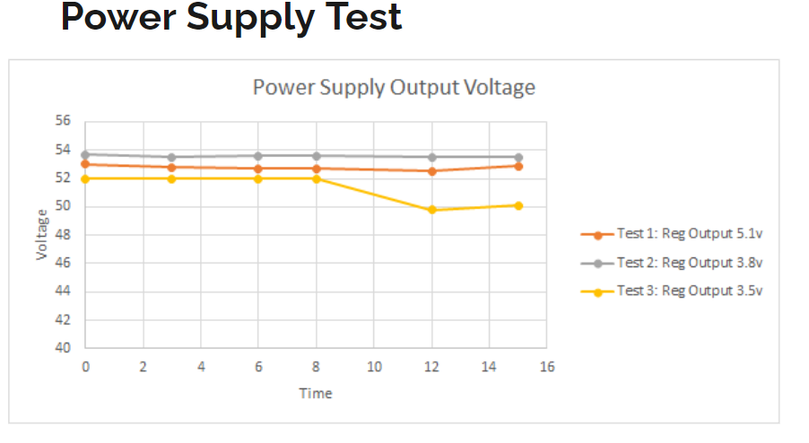
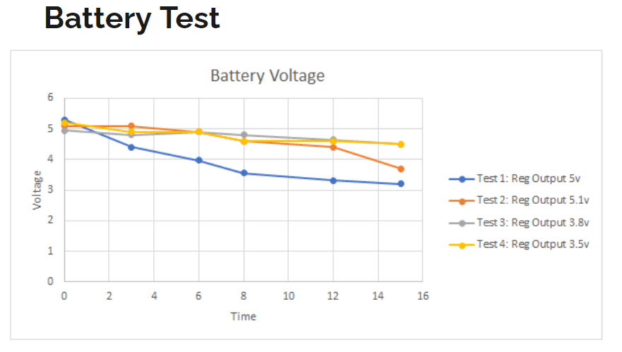
Our design solution is effective because it is able to keep the size requirements needed for practical testing of the mouse. Due to the limitations of the chosen power supply we altered our design to include an additional battery. This battery has been implemented in series at 6V and is able to output our desired voltage at 60 V. The operation time is another important factor since this is going to be used for testing. Our prototype phase was able to sustain a high voltage output for 15 minutes with minimal drop in voltage which is reasonable due to limitations caused by the difference in size of components compared to a PCB. Unfortunately, there was unexpected spikes in current which prevented us from testing for the full hour. However, we believe these discrepancies were caused by testing breadboard size components and not on the PCB.
HOW WE VALIDATED OUR DESIGN SOLUTION
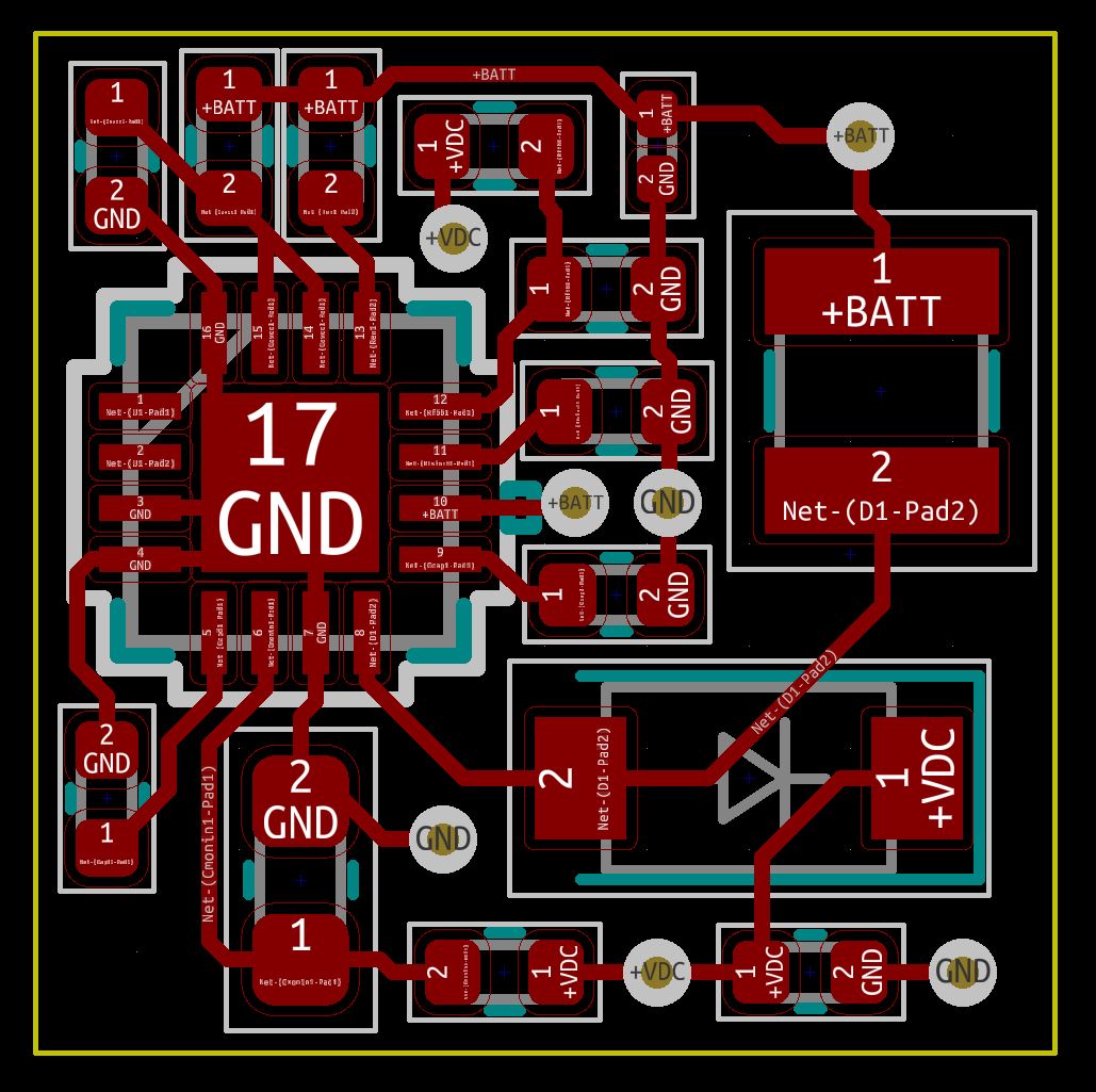
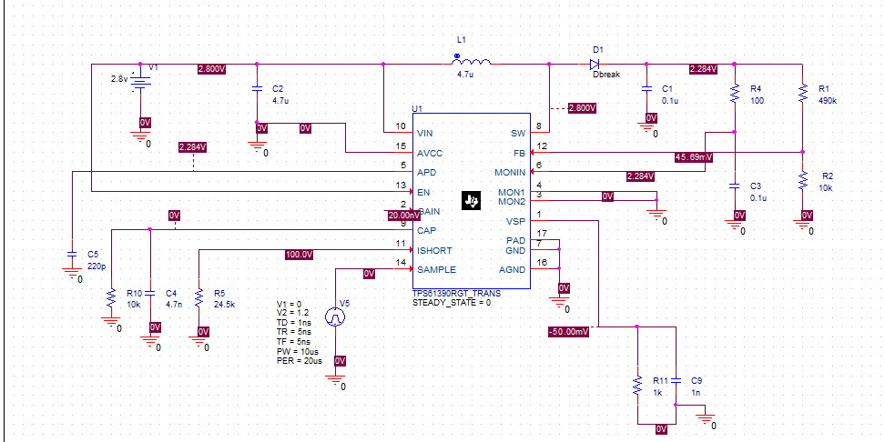
Designing Printed Circuit Boards to fit a small form-factor application proved to be a challenge. Even with modern electronic component package sizes, attempting to fit an entire power supply within 1 cm^3 requires a lot of placement manipulation; however, we were able to meet our design requirements while also maintaining some feasibility when it came to component selection. As shown in our schematic, our board uses SMD packages which creates some efficiency when it comes to soldering as reflow ovens can be utilized. Speaking of efficiency, our PCB design allows us to manufacture multiple (~25) boards for the price of one common $10 board. Finally, the extremely small nature of our board means that we will be able to achieve seamless integration with the rest of the “on-mouse” device as a majority of the entire device’s bulk comes from the power supply.
FEASIBILITY OF OUR DESIGN SOLUTION
The feasibility of our design is uncertain due to the discrepancy between our model and experimental predictions. Our simulations demonstrated that we could power the SiPM at 60V with 50 microamperes for one hour using one 3 Volt battery. However, our experimental validation showed that we needed 5.5 volts to generate a 60 V output with 2 mA. We are still unsure of the explanation for this discrepancy, but we have ordered our PCB along with our smd components to test if the difference was caused by our breadboard validation. Our PCB arrived on Monday, but we are unable to test it in time for this capstone fair.
Further directions include validating our PCB design, modifying our PCB for an LED as an input for the optical fiber, selecting and choosing a PIC microcontroller that can store data for one hour, and then testing it in a mouse.
Partners and Mentors
We would like to sincerely thank Kathryn Simone as our academic advisor for assisting using our design review, technical expertise, and feedback and design validation. We also would like to thank Professor Kartikeya Murari for giving us this project and providing us with his lab space, instruments, guidance, and feedback. Finally, we give our thanks to Zahra Kibrikoo for helping us navigate our course deliverables and advocating on our behalf.
Our photo gallery