Project Category: Electrical
Join our presentation
About our project
For this project we have redesigned the power systems for an upstream gas processing facility in order to contain modern modular components in an indoor facility with a small footprint for ease of maintenance. In a changing world and a changing political environment it is advantageous to build facilities with smaller environmental impact. Therefore this design will include a list of measures that improve the facility’s environmental impact by reducing fugitive emissions.
Meet our team members
Jacqueline Cottingham
Hailing from beautiful British Columbia, Jacqueline is focused on sustainable energy and sustainable building design. She completed her internship with BC Hydro working at 2 of the largest hydroelectric generating stations in British Columbia. During this internship she was supervised by maintenance engineers and worked closely with tradespeople who maintained the equipment. She hopes to utilize this experience on this project to design a facility that is functional and efficient to maintain.

Anita Rezaee-Anzabee
Anita is currently completing her final year of electrical engineering undergraduate degree. She has completed two internships in the fields of firmware and software development. She has taken part in multiple projects such as implementing BLE mesh network on IoT devices to expand the wireless network. After graduation, Anita will continue to learn new technologies and skills to work as a full-stack developer.

Austin Tang
Austin is a 4th year electrical engineering student. His technical electives focus on power systems including electrical machines/motors and photovoltaic systems. He has worked on several group projects at the University of Calgary including a course navigating robot and an automated greenhouse design. Austin is currently developing his AutoCAD skills in ENEL 584 – Electrical Systems in Commercial and Industrial Buildings in order to allow proficient work on the drafting aspect of this project.

Wilson Klym
Wilson is a 5th year electrical engineering student with a rich job history in many different facets of electrical design and automation. He spent two summers working with an Electrical Engineering company creating Automation and Electrical designs for Trans-Canada Pipeline Compressor Stations as well as another company designing the electrical systems of a large scale deep cut gas plant subcontracted for Bellatrix Exploration. This involved PCB design, AutoCAD drafting, PLC programming, and Engineering Documentation. Currently he is gaining experience doing systems management and facility operation at a Satellite tele-communications company working at a ground antenna array. This job provides insights into the ins and outs of RF communication, broadcast statistics, Unix programming, and 600V power system commissioning.
Details about our design
HOW OUR DESIGN ADDRESSES PRACTICAL ISSUES
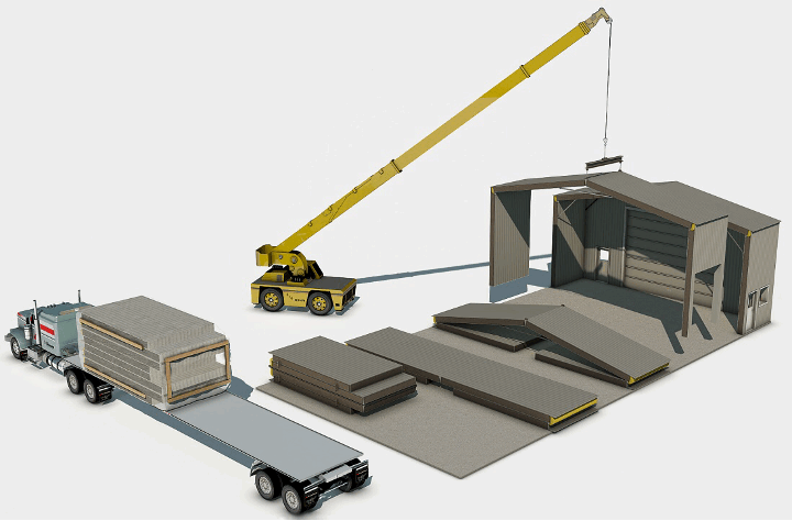
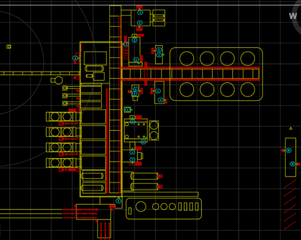
Modern modular components are not typically contained in a building and are usually spread out over a large area; as a result maintenance on these facilities is difficult, time consuming, and uncomfortable in many weather conditions. Designing a facility where these components can be contained indoors will result in easy maintenance and less exposure to the elements for equipment and staff. Reducing the footprint of the facility results in reduced materials costs for the building to contain the equipment.
WHAT MAKES OUR DESIGN INNOVATIVE
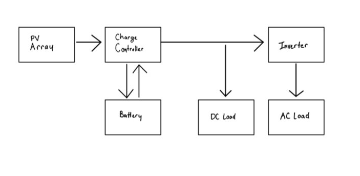
The design combines old and new techniques with the technology of the future for an oil and gas facility that is more environmentally responsible. Drawing inspiration from old oil and gas facilities which contained majority of equipment in a large permanent building, this design moves equipment closer together in a large modular building. However, this design uses modern equipment which is pre-fabricated, more modular and more economically efficient. Additionally, the design implements technology of the future including a photovoltaic system to reduce the gas burned at the facility. This design is a success because it selects the best technology from every generation of oil and gas facilities.
WHAT MAKES OUR DESIGN SOLUTION EFFECTIVE
Our design solution is effective because it features cost savings and reduced environmental impact due to major reductions in the following materials:
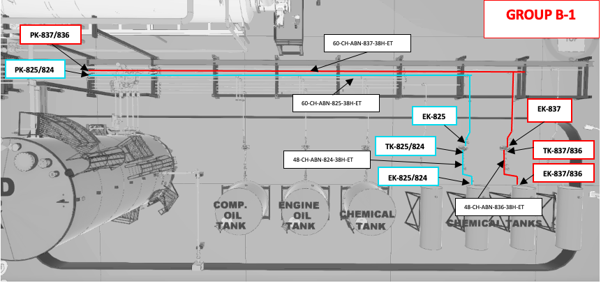
- Majority of the heat trace layouts and materials were able to be eliminated
- The total length of the cabling was reduced to half the original amount
- Heaters and lights see further reductions and increased cost savings
HOW WE VALIDATED OUR DESIGN SOLUTION
We validated our design based on:
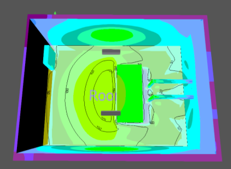
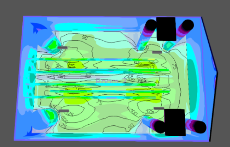
- series of cost benefit analyses were done to choose the lighting design
- compared the cable lengths to the original design which resulted in 48% reduction
- created an updated bill of materials for heat trace layout and compared it to the original bill of materials to show reduction in heater length, power kits, T-splice kits, and end kits
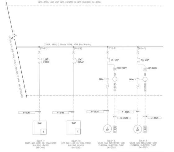
- The original facility load list was evaluated, and a load list for the new facility was created. A comparison of the lists revealed a reduction in power consumption by the facility
- Few design review stages were performed to present our designs to the sponsor and got feedback
- “Redline” drawings were created by peers within the members of the group to identify errors that needed to be corrected on the drawings
FEASIBILITY OF OUR DESIGN SOLUTION
Our design can be feasibly implemented in any new oil & gas processing facility because it uses widely available technology and equipment. Additionally, it is economically beneficial from construction through the lifetime of the facility. The project being more environmentally responsible than previous designs makes it more feasible to operate in a low carbon future.
Partners and mentors
We want to thank the many people who helped us with this project. During this project we got great guidance and advice from our sponsor Grey Owl Engineering and our academic advisor professor Chris Wood.
Our photo gallery