Project Category: Electrical
Join Our Presentation!
About the Torque Angle Sensor
The objective of the torque angle sensor is to aid Taifa Engineering in calculating the torque angle of a generator during maintenance and commissioning. Our project allows Taifa Engineering to measure torque angle without generator shutdown and also allows them to transmit this information up to 100 metres to a control station.
Currently, Taifa engineering measures torque angle by:
- Installing a piece of reflective tape on the generator’s rotor and using a sensor aimed at the piece of tape to measure when the rotor makes a full rotation.
- The sensor emits a 5V pulse whenever it views the reflective tape.
- An oscilloscope is used to measure this pulse in addition to the terminal voltage of the generator.
- The phase shift between the two signals when the generator is loaded will equal the torque angle of the system (calibrated with respect to a no-load reference point).
- Approximately 300 feet of cable is run between the contact sensor to the control room to get the reference terminal voltage.
The aim of this project is to prevent a shutdown of the generator for testing, maintenance and/or commissioning. The torque angle solution employs a through-beam sensor that creates a square wave as exposed bolts on the generator shaft interrupt the laser between the transmitter and receiver. The sensor is connected to our uniquely designed PCB which additionally functions to receive the terminal voltage signal from the generator for comparison. The embedded microcontroller compares these signals and employs our torque angle algorithm software to output the torque angle wirelessly for a range of up to 100 metres.
Meet our team members


Janam Marthak (Project Manager): Janam is interested in hardware and software design, specifically embedded systems. He worked on-site at the nuclear power plant Bruce Power, where he was part of the lifecycle extension program. One of the highlights of his experience was going into the vault to see how fuel cells are inserted. In his free time, he is very interested in learning about finance, capital markets and quantitative investment strategies to gain better business knowledge and strategies for product development.
Flaviu Manzat (Testing Lead): Flaviu is an electrical engineer interested in electrical energy and power systems. He worked with the federal government in the department of national defence on the sustainment and operation of arctic military infrastructure. In his role he worked with project engineers on system sustainment and asset life-cycle management alongside subject matter experts and government technical authorities.
Sourav Saha (Documentation Lead): Sourav has developed his interest in power systems, protection and renewable energy technologies through a mix of coursework and applicable industry experience. He has completed an internship with Suncor’s Firebag reliability engineering team. A highlight of this experience was a four month placement on site, where he worked with maintenance personnel and field engineers to implement an arc-flash mitigation program and participate in maintenance activities during turnaround (breaker and starter replacement, oil tank storage inspections, etc).He has also completed coursework in alternative energy systems, nanotechnology and transmission lines to gain a broad understanding of evolving power system technologies that will become relevant in the coming years with a push towards renewables.
Mikhail Karpushin (Technical Lead): Mikhail is passionate about the technical aspects of the power industry and power systems related material. Mikhail worked at Husky Energy in a SAGD oil sands field facility where he performed a range of projects in areas including lighting, heat tracing, motor relays, power redundancy, and power electronics. A key highlight of Mikhail’s experience working on-site was having the opportunity to photograph and observe first hand how electrical equipment was removed and tested during a turnaround (e.g. switchgear breakers, transformer windings, power factor correction capacitors, etc.)
Mahesh Aryal (Hardware Lead): Mahesh is interested in system engineering with focus on avionics systems. Before pursuing his electrical engineering studies, he worked as an avionics technician for more than 5 years. He recently completed his 14 months internship at Enerflex where he worked mostly in designing control systems and heat-tracing systems for Gas Processing Plants. He is also pursuing an Operations Management degree and he aims to analyze how organizations operate and increase their efficiency by optimizing the resources.
Devon Vipond (Software/Firmware Lead): Devon has interests in working on networking and embedded devices. He recently completed a 12 month work term at General Dynamics Mission Systems-Canada and a 4 month work term at Amazon, where he gained experience with working on embedded linux applications and web technologies.
Details about our design
HOW OUR DESIGN ADDRESSES PRACTICAL ISSUES?
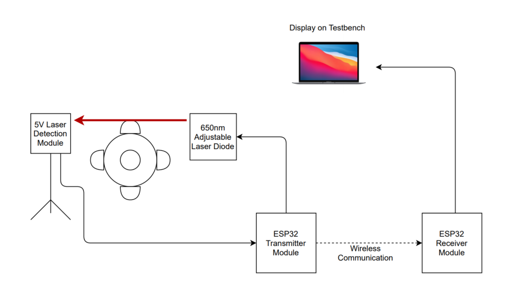
Simplified integration diagram of sensor and wireless solution
- We use a through beam sensor design to create a point of reference of the stator voltage signal at no-load condition. Upon loading, the comparison of the change in phase angle with respect to no-load allows us to calculate torque angle without generator shutdown needed.
- The ESP32 transmitter module allows us to wirelessly transmit the calculated torque angle up to a distance of 100 metres which eliminates the need to run cables to the control room.
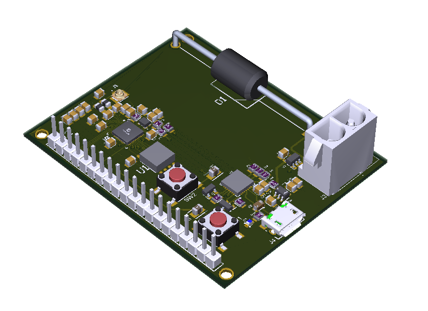
- The integrated PCB allows easy interfacing with the recommended sensor (to be used in the field) and seamlessly allows the microcontroller to calculate the torque angle using our torque angle algorithm.
WHAT MAKES OUR DESIGN INNOVATIVE?

Block Diagram of the Torque Angle sensor and Wireless Solution Interface
- The terminal voltage of the generator is fed through into a hysteresis comparator circuit which outputs a digital rising edge signal at moments of zero-crossing transitions into negative polarity voltages. This results in a periodic digital square wave signal from the stator voltage.
- The system allows the user to select bolt inputs during the setup procedure to establish a baseline of the system (to “zero” the system).
- The torque angle sensor (SmartEye-XPro) outputs timestamps of bolt protrusions after loading. The microcontroller compares the timestamp differences between adjacent array indices and compares that to the baseline in order to determine a torque angle.
- Our product warns the user when the generator is reaching a point of critical stability (any generator with torque angle above 90° becomes unstable).
WHAT MAKES OUR DESIGN SOLUTION EFFECTIVE?
Clock drift is the largest source of error in calculating the torque angle when transmitting wirelessly.
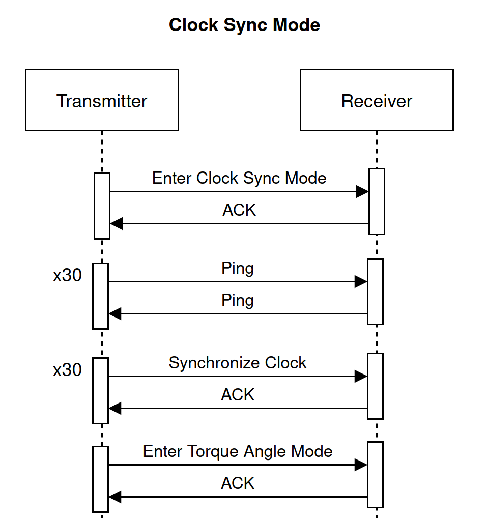
Clock synchronization is required to prevent clock drift. As we are using a cost-effective oscillator, we need to synch the internal clocks of both the transmitter and the receiver. During clock sync mode, the transmitter and receiver are solely focused on the task of clock synchronization. All extraneous tasks (e.g calculating torque angle, time-stamping sensor data) are halted.
The transmitter will enter clock sync mode once every two minutes. After entering clock sync mode, the transmitter will command the receiver to enter clock sync mode. The receiver will send an acknowledgement to the transmitter after it successfully enters clock sync mode.
After the transmitter and receiver have entered clock sync mode, the transmitter will time the RTT for 30 ping’s over the network. Then it will remove any outliers from the RTT dataset. Finally, it will take the average of the remaining RTT’s to find the average RTT of the network.
After determining the RTT of the network, the transmitter will send 30 clock synchronization packets to the receiver. Before the receiver can use this data to sync its clock, it will need to remove any outliers from the dataset (approximately 10% of the packets will take far longer than RTT/2 to traverse the network).
Since our solution provides a cost-effective way of wireless transmission of the sensor data with a high degree of accuracy, we are able to achieve accurate transmission using the internal clocks of the microcontroller without adding any additional oscillators.
HOW WE VALIDATED OUR DESIGN SOLUTION?
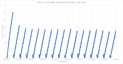
The figure on the left shows the results of our verification for the clock synchronization mechanism. We can see that every 160 seconds, synchronization of the clocks almost eliminates the torque angle error caused by clock drift. As time progresses, the error begins to linearly increase at a rate of 0.145 degrees/second until the clocks are synchronized again.
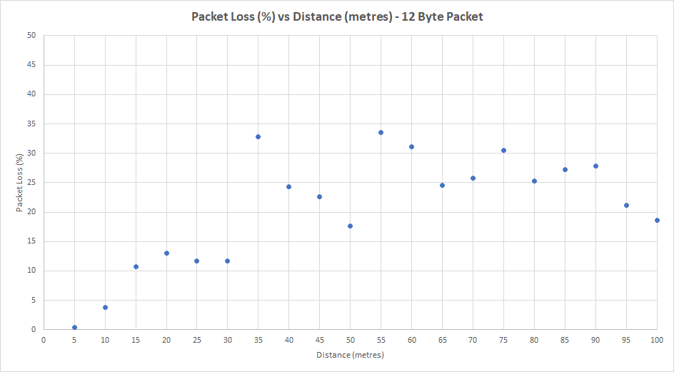
The % packet loss as a function of distance is shown on the figure on the left.
The results of this test were used to determine the packet size used for wireless transmission.
Partners and mentors
We want to thank the many people who helped us with this project. Our academic advisor Dr. Andy Knight guided us through the process with patience and great advice. And, our consultation Taifa Engineering to understand their problem better was invaluable.

Taifa Engineering Ltd. is a Canadian Consulting and Engineering Services Company comprised of Professional Engineers specializing in power system engineering, as well as engineering field services. Our team is adept in all aspects of power system engineering in power generation, transmission, distribution and renewable energy programs

Transmission Electric Industry Chair
Dr. Andy Knight’s research group key areas of interest are: sustainable electrical energy systems, focusing on the integration of renewable energy into electric grids through systems analysis and experimental validation, and; electromechanical energy conversion, including electrical machines, drives and associated power electronics.
