Project Category: Electrical
Join our presentation
About our project

Our team has been working to create a system that simulates the electrical properties of train movement on freight rail so that our sponsor, CP Rail, can safely test new electrical equipment in a lab environment. This eliminates the risks associated with traditional equipment testing on real rail which has the potential to interfere with existing equipment such as rail crossings.
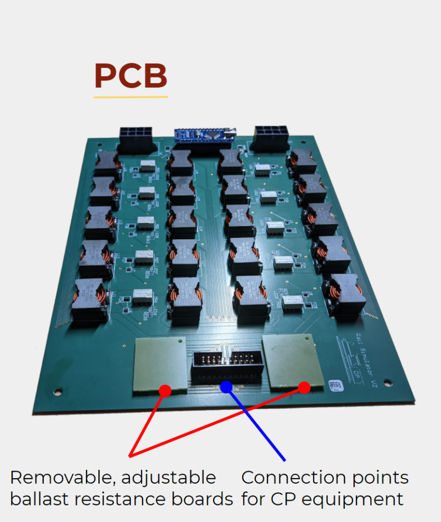
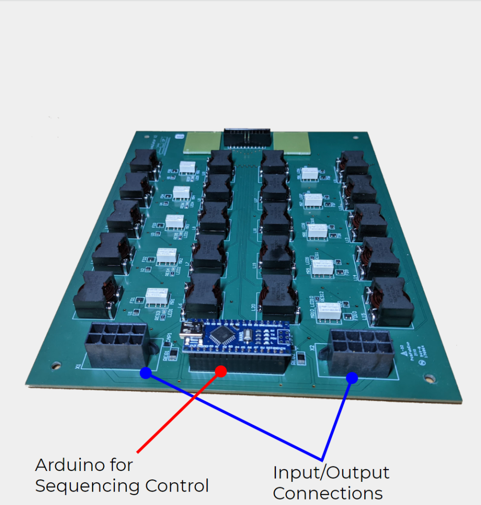
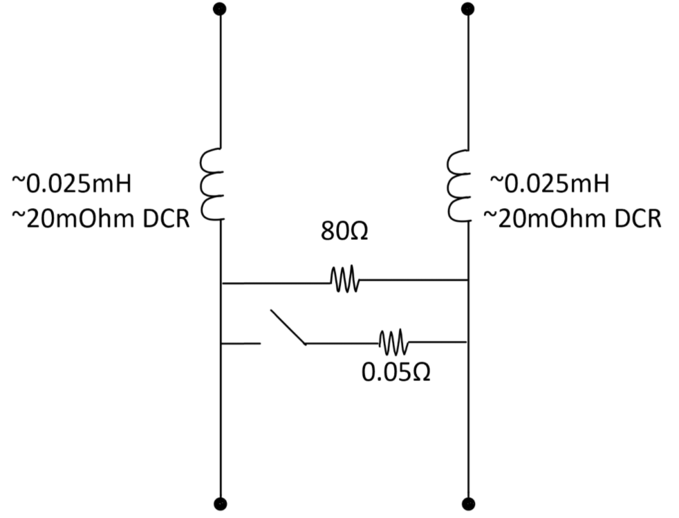
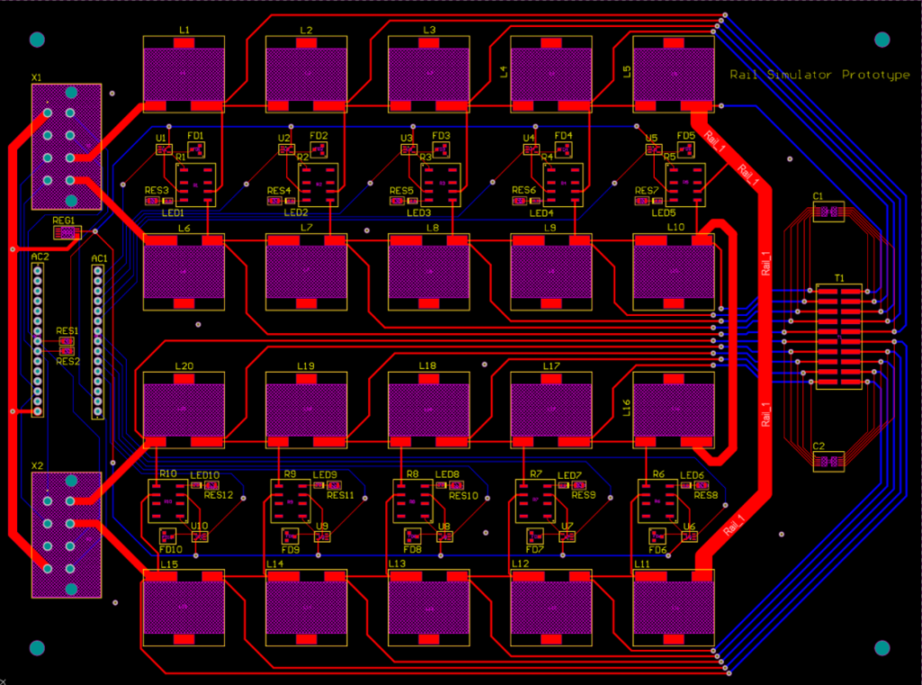
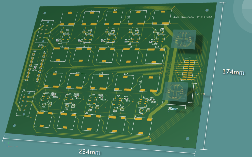
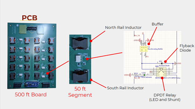
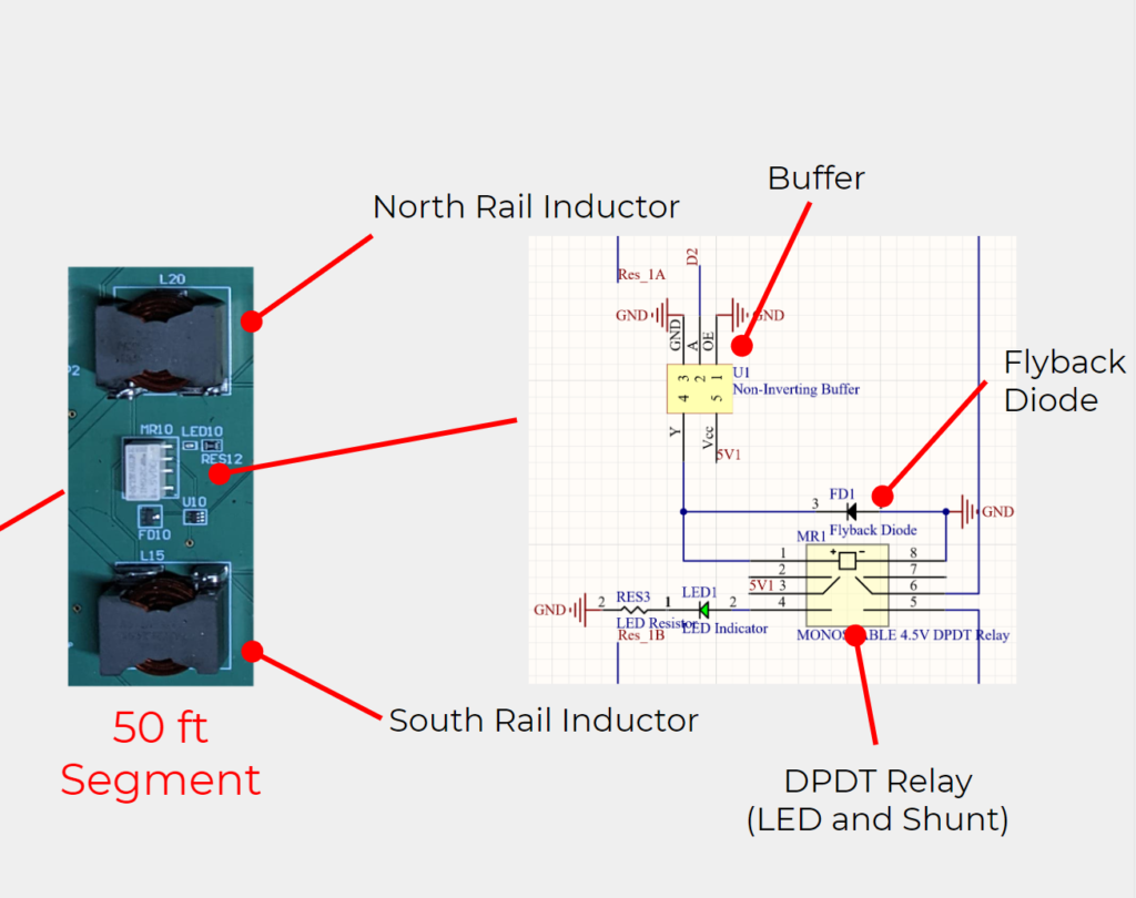
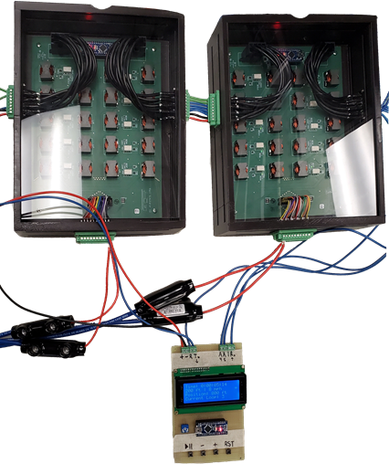
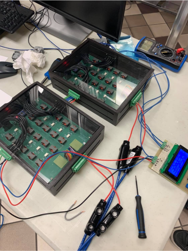
We created a modular PCB design for this project since it allowed us to have complete freedom over the design’s strict electrical requirements. The PCBs, each of which electrically represent 500ft of rail, emulate train movement by activating relays every 50ft from a series of communicating Arduinos. The relays connect the simulated rails together as if the real wheels of a train were connecting real rails together. Each PCB easily connects to the next, allowing for endless simulated rail to test. Furthermore, we have designed small interchangeable PCBs to vary the resistance between the rails, allowing for different conditions/materials, such as concrete or wood, to be considered.
We hope that our project will not only simplify the future testing procedures at CP Rail but will also make sure that nobody in the future will get injured as a result.
Details about our design
HOW OUR DESIGN ADDRESSES PRACTICAL ISSUES
Our design offers CP Rail to test rail wayside equipment in a lab environment rather than on live freight rail. Currently, in order to conduct wayside testing, the equipment would be needed to connect directly to rail which would require workers to shut down rail sites and prepare testing procedures. This process can be time-consuming and expensive. By transferring the electrical properties of freight rail and train movement onto a PCB, CP Rail can eliminate these problems and allow for testing at any time within a lab environment.
WHAT MAKES OUR DESIGN INNOVATIVE
We were able to effectively simulate both rail and a moving train onto a significantly smaller system. By implementing rail onto a PCB, we were able to convert 500 feet of rail to under 1 square foot of PCB. Additionally, train movement was implemented with Arduino microcontrollers. These microcontrollers allow for adjustable capabilities such as train speed, movement, direction, etc.
Our design is modular, expandable, and easy to use. With each PCB representing 500 feet of rail, expandability is achieved by adding more PCBs in series. The user interface we implemented accounts for variable adjustments, allowing the user to set the simulation to their desired conditions in a straightforward manner. This innovative design meets all the deliverables required to simulate freight rail in a lab environment.
WHAT MAKES OUR DESIGN SOLUTION EFFECTIVE
There are three major aspects that make our design solution effective: modularity, expandability, and ease of use.
Modularity
To assemble our design, PCB segments, representing 500 feet of rail, are attached in series with a master Arduino being at the start/end of the loop. PCB segments are not addressed to a single location on the track. This means that segments can be swapped and replaced easily.
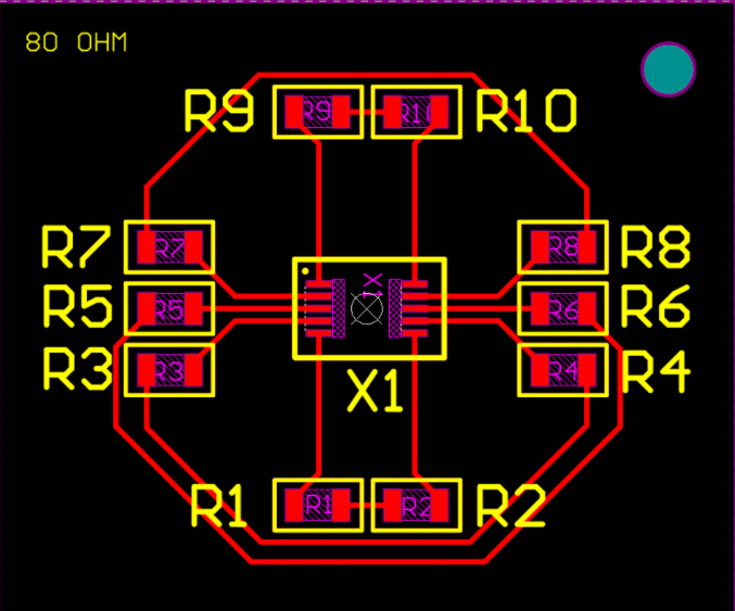
Adjustable ballast resistance (resistance between rail) was a requirement that our design achieved. To meet this deliverable, 50-foot segments would route to connectors located on our boards. These connectors would attach to a predesigned resistor board (10 resistors each routing to a 50-foot segment). To adjust the ballast resistance, users can simply replace the resistors on the board with their desired ballast resistance. The resistor board then has plug-and-play functionality.
Expandability
One of our major deliverables was to prove that our design was expandable for up to 8 miles. This is easily achieved by combining as many desired PCBs in series (85 PCBs for 8 miles). The Arduino is also designed to locate all PCBs and their position making train movement/shunting effective the whole way through.
Ease of Use
To make our project user-friendly, our team implemented a user interface with the master Arduino. It utilizes a 20*4 LCD screen and 4 buttons to navigate the interface. Users can adjust train speed, length, and direction (east or west). The train can also loop through the track with a variable time setting between loops. PCBs are also designed to connect in series with a short connector. Inputs and outputs are designed for all pins to line up from board to board allowing for quick and easy connections.
HOW WE VALIDATED OUR DESIGN SOLUTION
Hardware Validation
The final validation tests that we decided on for the PCB included testing impedance and inductance values, confirming voltages at various points during powered operation, and ensuring that the board performed as expected by CP Rail’s ElectroLogIXS equipment. Additionally, since our design is modular, we had to ensure that we measured expected values across multiple boards when connected together.
Software Validation
Software validation tests included timing train shunting, communications testing, and user input edge case testing. We first perform all tests on a breadboard to prove the functionality of our design and then finally validate by testing on the PCB. To test modularity and expandability, we had to ensure all tests apply across multiple connected Arduinos.
FEASIBILITY OF OUR DESIGN SOLUTION
We designed our system to be modular, expandable, and easy to use so that the people at CP Rail can benefit from our system as much as possible. Here is a list of features we implemented to meet this requirement:
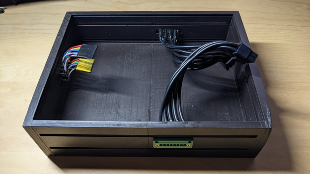
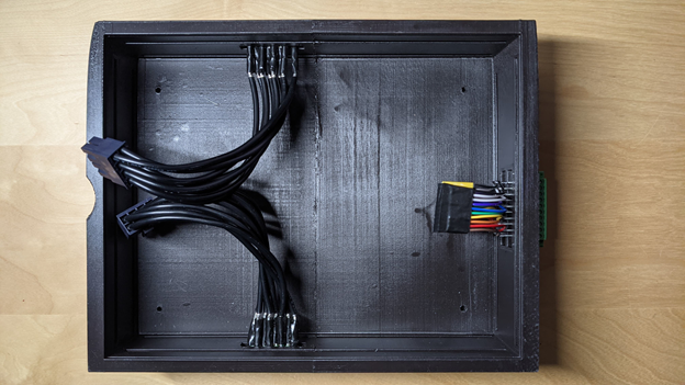
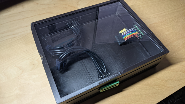
- Physical hardware is small and compact making it portable and expandable.
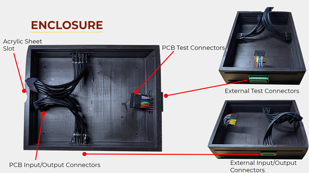
- Test connectors provide node access every 50 feet for a high variety of testing locations.
- Input and output connectors are set for easy plug-and-play operation.
- The user interface is easy-to-follow, and it accommodates for human error.
- Simulation code is scalable, allowing the possibility to incorporate more functionality if needed.
Partners and mentors
We would like to acknowledge Canadian Pacific Railway for sponsoring our project as well as Alison Brayman and Laura Thompson, who work at CP Rail, for their continuous support. Additionally, we want to thank our technical advisor, Norm Bartley, and our teaching assistant, Udoka Nwaneto, for guiding us on our project.


