Project Category: Geomatics
Join our presentation
About our project
Our project is about computing the optimal spacing between wellbores. Wellbores are holes drilled into the ground that allow the recovery of natural resources, such as oil and gas from reservoirs. Reservoirs are a formation of rock in which oil and gas has accumulated. In Oil and Gas reservoirs, spacing between wellbores is one of the most important methods of measuring the performance of individual wellbores. Computing wellbore spacing also provides insight into how reservoirs can be planned to best optimize production. Knowing the optimal distance to space wellbores increases production and efficiency by having the wellbores extract the maximum amount of oil without interfering with each other. This increases not only the amount of oil extracted but also how fast the oil is extracted since the wellbores cover a bigger area. This also achieves maximum economic benefits due to not having to drill unnecessary wellbores.
Meet our team members
- Jacky Zhou
- Ajay Saini
- Zelin Zhou
Details about our design
HOW OUR DESIGN ADDRESSES PRACTICAL ISSUES
Originally, wellbore spacing was computed in 2D by using built-in measuring tools in GIS programs like ArcMap and QGIS. This method had many issues such as:
- Most reservoirs develop wellbores in both horizontal and vertical directions, therefore making it much less applicable in practical scenarios
- The scale of the map and the point along the wellbore that was used to measure the distance highly impacted the accuracy
- Since basins have 20,000 wells, manually measuring the distance between each well was time-consuming and inefficient
WHAT MAKES OUR DESIGN INNOVATIVE
Our design calculates the spacing in three dimensions as opposed to two and automates the calculation of the wellbore spacing so that it is much less time consuming and much more efficient.
WHAT MAKES OUR DESIGN SOLUTION EFFECTIVE
Our solution is more applicable to practical scenarios and more efficient due to the automation of the results.
HOW WE VALIDATED OUR DESIGN SOLUTION
We validated our design approach by comparing our design results with manually generated results in ArcGIS.
FEASIBILITY OF OUR DESIGN SOLUTION
We believe that our design is feasible when compared to the older method of wellbore spacing computation
Partners and mentors
We want to thank the people who have helped us with this project. Our team advisor Adam Thomas for guiding us through the project and answering any questions we have and our professor Michael J. Collins.
Our photo gallery
References
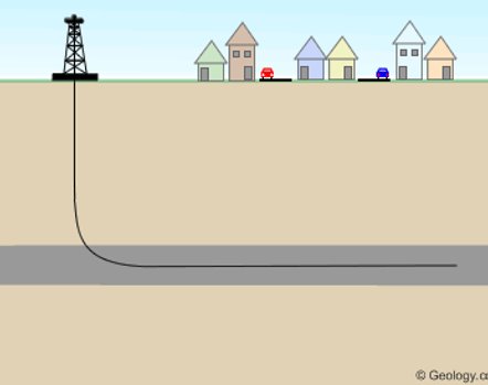
Figure 1. King, H. M. (n.d.). Directional Drilling under City. Directional and Horizontal Drilling in Oil and Gas Wells. geology.com. Retrieved from https://geology.com/articles/horizontal-drilling/.
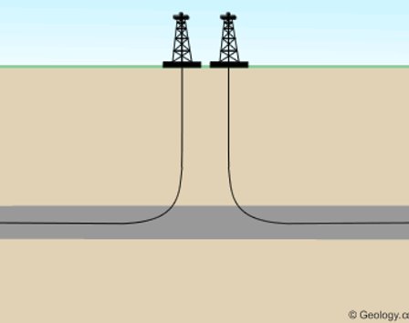
Figure 2. King, H. M. (n.d.). Drain a large area from one drill pad. Directional and Horizontal Drilling in Oil and Gas Wells. geology.com. Retrieved from https://geology.com/articles/horizontal-drilling/.
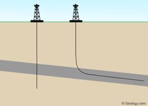
Figure 3. King, H. M. (n.d.). Increase the length of the “pay zone”. Directional and Horizontal Drilling in Oil and Gas Wells. geology.com. Retrieved from https://geology.com/articles/horizontal-drilling/.
