Project Category: Mechanical
Please Join Our Meeting
About our project
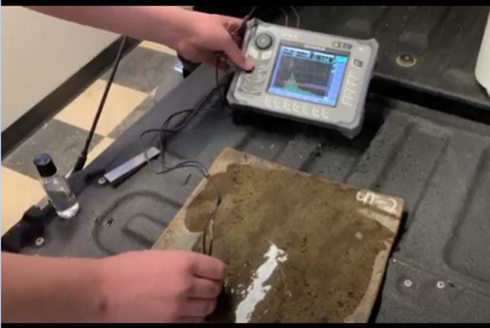
- Inspections are an essential part of industrial asset integrity to avoid disasters and ensure safe practices. This Capstone project focuses on inspection of oil and gas storage tanks which are naturally subjected to corrosion; leaving behind small pockets on the steel tank floor known as pits which can potentially lead to leakage of resources. These tank floors are not only vulnerable to topside corrosion (fluid and floor), but also underside corrosion (floor and soil), which is not visible to the naked eye. This necessitates inspection through the use of ultrasonic testing to verify that the remaining material thickness satisfies regulations and standards. The current implementation requires moving a small sensor by hand across a specified area (typically no more than 12”x12”) which contains inherent problems that we aim to solve with our design.
- Our objective is to create a device that will automate the current inspection process of ultrasonic testing to provide efficient and reliable risk assessments of specific areas of interest that will minimize inspection times and operating costs. In addition, the device will be compatible with a variety of ultrasonic equipment to incorporate some level of flexibility and be built with off the shelf components to allow future modifications.
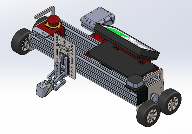
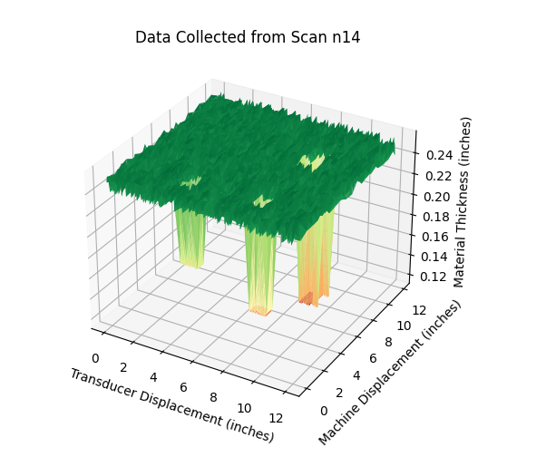
- The device operates using two stepper motors controlled by a Raspberry Pi 3B+ to sweep a scanning ultrasonic probe across the prescribed area to ensure total coverage. As scanning proceeds, the data collected by the single board computer will populate a heat map that will directly reflect the location and severity of pitting.
- To ensure continued development of the software this project is publicly available at: https://github.com/mporeilly/Automated_Ultrasonic_Device
- The final cost is $1200/device.
Meet our team members


Chase Casavant
Daniel Daragan
Eldon Dunnet
Matthew O’Reilly
Michael Nel
Details about our design
HOW OUR DESIGN ADDRESSES PRACTICAL ISSUES
Issue: The current implementation of pitting inspection is rather tedious and prone to error. Operators are required to inspect multiple areas of concern (12”x12”) on their hands and knees using a small probe (1”x1”) which as a result depends on the operator’s skill to accurately assess the associated risk levels. Therefore, it is possible for undetected pits to remain at risk and avoid repair.
Solution: By introducing two stepper motors, the device is capable of scanning the entire area. One motor sweeps the scanning probe along the full width of the desired area while the other motor moves the driving wheels forward at increments between probe sweeps. The combined movement will produce a serpentine path to ensure the floor is fully covered with minimal operator input.

Issue: Current commercial variations of automated ultrasonic inspection devices generally require a fully integrated set of equipment which is extremely costly at typically $40,000 – $50,000 per unit. If a single piece of equipment malfunctions, it is possible for the device to become nonfunctional. Furthermore, Nextgen already has invested tens of thousands of dollars in ultrasonic equipment that would be incompatible with commercial options, thus making it essentially useless if moving to all automated inspections.
Solution: To overcome this problem, our device is universally compatible with various ultrasonic equipment and consists mainly of off the shelf components that can easily be obtained at local stores and major online distributors. Having a generic frame allows Nextgen to use their current equipment and automate their inspection process for a far smaller investment compared to commercial options. This also makes maintenance quick with replacement parts easily available and allows for future upgrading with new equipment or parts.

Issue: Operators are limited in their ability to record inspections in a digital format to provide to customers. The current process involves finding the thinnest spots and marking down the values by writing on the floor itself. As a result, there is no current way to provide a historical record of the entire plate section that is easy to reference in the event of future inspections.
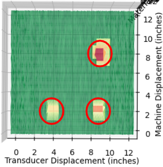
Solution: By using our Raspberry Pi, the data collected during the scanning process is saved to a CSV file in real time. The file is then used to populate a heat map that illustrates key points of risk within the area of concern. This process provides easily readable and accessible data collection for both users and clients to understand the entire thickness of the area scanned.
WHAT MAKES OUR DESIGN INNOVATIVE
Due to the variety of pre-existing ultrasonic equipment available, our device has incorporated several design choices to integrate universal compatibility with a variety of ultrasonic scopes. This will allow operators to use the inspection device regardless of the equipment they currently possess at a significantly lower cost compared to commercial options. Furthermore, maintenance and future upgrading will be easier with greater interchangeability.
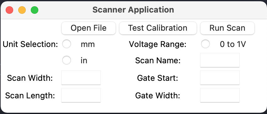
The automated inspection device incorporates a graphical user interface (GUI) to assist the operator in scanning operations with adjustable features. These features include custom scanning dimensions, the choice of imperial or metric units, and the ability to pre-name data file names. In addition, the GUI provides a visual representation of the heat map which reflects the data collected from the scope. This heat map can be easily understood by clients and provides stored quantitative values for the whole area scanned, unlike the current method of writing the thinnest measurements on the floor by hand.
WHAT MAKES OUR DESIGN SOLUTION EFFECTIVE
After receiving the prescribed inputs from the operator, the device is capable of independently completing the scanning process without further guidance. This allows the operator to manage multiple devices at a single instance and as a result, will reduce the overall inspection time for storage tanks and allow operators to complete inspection tasks with a higher level of efficiency. Using the current prototype, three devices operating at the same time in separate locations is the breakeven point compared to a single operator manually scanning by hand.
The decision to build the automated inspection device using simple off the shelf components makes the device cost-effective and easy to manufacture even with limited machining capability. Basic shop tools like an angle grinder, drill, and hacksaw can be used to create the frame. As such, dozens of our devices could be made for the cost of one commercial scanner, making an effective fleet of automated devices that would greatly shorten overall inspection time.
As current inspection methods involve the inspector to go on their hands and knees, our device eliminates that need and includes several ergonomic features that will assist operators in the field. The combination of aluminium rails and steel handles, make the device relatively lightweight (approximately 10 lbs) and easy to manage when traversing between locations. In the case of an emergency, an emergency stop-button has been added to halt all functions of the device.
Through our testing methods of the final prototype, it is proven that our design provides speed improvements when using three or more devices for each operator. Furthermore, the device is sufficiently accurate in compliance with API 653, with the heat map determining actual pit locations within ½” in the X-Y direction and remaining metal thickness within 0.001”. Also our device is reasonably durable to survive a full day of inspections, with minimal maintenance over 200 scans, and is operational in a variety of seasonal temperatures.
HOW WE VALIDATED OUR DESIGN SOLUTION
Initial Design
During the initial design, several variants of the device layout were considered with pros and cons being the determining factors.
- Square: Rigid structure that would allow for simplistic movement while protecting the device. However, it was decided to be unsuitable due to its large size be an issue with varying tank entry-way sizes
- Cross: Collapsible design consisting of two independent rails that would provide simplistic management while maintaining full scan capabilities. The removal of additional rails does make this design susceptible to damage; thus removing it from consideration.
- Roller: Compact design that combines two styles of stepper motors to produce a combination of linear motion in two separate directions. This would allow the device to have unlimited capabilities in a single direction allowing for larger scanning capabilities.


Using these design layouts, our team was able to validate that the roller design was the most effective solution.
Design Development
After selecting the main design, various types of components were considered by comparing the advantages and disadvantages of each.
- Stepper Motors vs. DC/AC Motors – Stepper motors were chosen for the ability to easily control them as well as the ability to calculate location.
- Raspberry Pi vs. Arduino – The Raspberry Pi was chosen since it allowed faster development with Python and had higher level interfaces like USB supported natively.
- Timing Belt vs. Lead Screw – Timing belts were determined to be faster, cheaper and require less maintenance.
- Wheels vs. Treads – Wheels were found to be easier to implement than treads, as wheels are not as complex or expensive.
Prototype Development
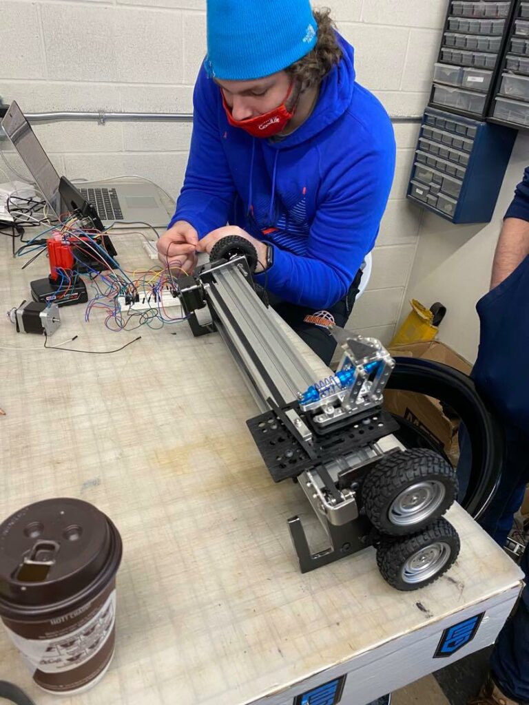
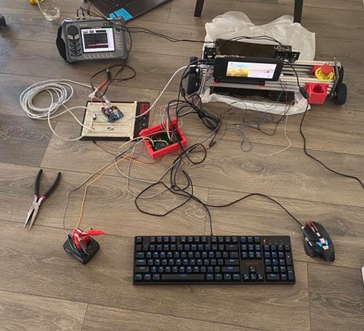
Thanks to our sponsor Nextgen, our team was able to build a physical prototype of the Roller design that could be used to verify that the chosen design considerations were able to satisfy the design criteria. Any components/design choices that were unable to meet the required tasks were reassessed by our team and updated to reflect a more complete project. One such example was the introduction of an Arduino microcontroller. During initial testing, it was found that the Raspberry Pi was incapable of controlling the stepper motors and data collection due to electrical interference between the General Purpose Input/Output (GPIO) pins. As a result, an Arduino was included to manage data collection and send data via a serial connection to the Raspberry Pi.

Final Prototype and Testing
Using the physical prototype and the skills of experienced operators, our team was able to run several experiments to assess the device’s speed, accuracy and durability.
- Speed: The device was timed against an experienced operator using an identical sample piece. This process was repeated several times to ensure that the device was quicker than the operator. The operator took an average of 4 minutes to scan and identify all the pits on the plate. The device took an average of 10 minutes, which is significantly longer. However, the initial setup time for the device took a bit longer than 1 minute. Thus, comparing the time for one operator to scan 3 areas to 3 devices scanning 3 areas, the times become even at 12 minutes. Furthermore, running subsequent scans with the device takes only 5-10 seconds to set up, making it faster than an operator in the long term, as most tanks have hundreds of areas to scan.
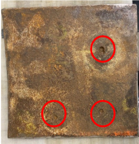
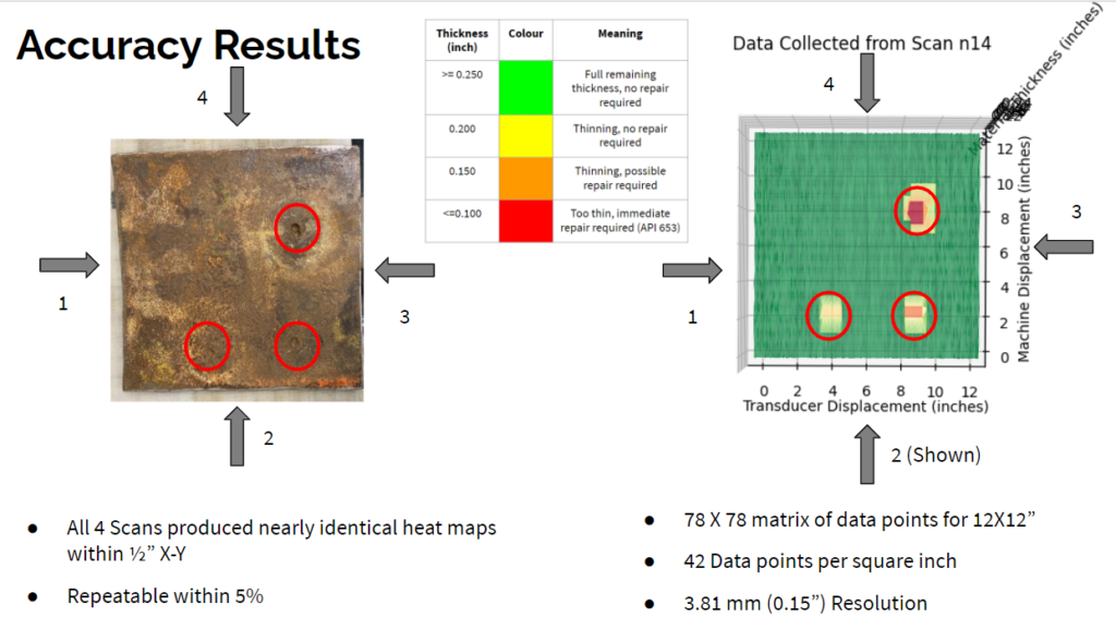
- Accuracy: A test plate consisting of known pit depths and locations was scanned by the device in all 4 directions to generate 4 data sets. These data sets were used to create 4 heat maps that were then compared to the original plate to determine the overall accuracy of both position and depths of present pits as well as each other for repeatability. The device was successful as all 4 scans produced nearly identical heat maps within ½” X-Y and were repeatable within 5% of one another.
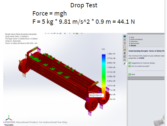
- Durability: The device was set to perform numerous trials until maintenance was required. During this time, each maintenance procedure was recorded to ensure that repairs did not exceed 10 minutes. Additionally, the team also considered any components that did not fail during these trials to verify that any part of the device can be easily fixed within our defined repair time. In testing, the device ran 200 scans with the minimal maintenance of tensioning a belt. All other maintenance and repairs were simulated and took less than 10 minutes. The device was functional in environments below 0°C and above 20°C, and survived a simulated drop test at 90 cm (height of carrying at the hip) using Solidworks simulations.
FEASIBILITY OF OUR DESIGN SOLUTION
Our prototype met all the design requirements established by the problems facing Nextgen and provides a more operator friendly device while being under the budget of $2000.
- Due to the teams decision to use easily available components of relatively low cost, a single device can be built for approximately $1200; a large decrease from the proprietary cost of $50,000. This provides motivation to build several devices as parts are low cost, easily accessible, and will decrease inspection times due to the automated nature of the device.
- The completion of the first device has minimized the build times for future devices as many steps of the initial prototype have been completed. This includes the software to operate the device, custom part designs for assembly and a custom printed circuit board for the wiring of the device. As a result, a fully operational device can be completed in approximately 2 to 3 days (first device took approximately 6 working days). It could be further improved by utilizing more efficient manufacturing processes such as plasma cutting or waterjet cutting.
- Lastly, the device can be easily upgraded over time due to the simple parts and build process. This provides a longer work life for the device as it can be easily maintained/altered to reflect future iterations. This establishes further incentive to use this device over proprietary equipment that costs thousands of dollars to update to a new generation.
| Design Requirement | Condition Satisfied |
| Automated with Minimal Commands | Yes |
| Implements Off the Shelf Components | Yes |
| Proper UT Function | Yes |
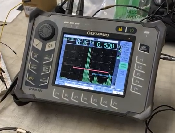
| Universally Compatible with Olympus UT Scopes | Yes |
| Historical Results Stored | Yes |
| Accurate Heat Map Generation | Yes |
| Reduction in Inspection Time | Yes |
| Scans are Positionally Repeatable to Within ½” | Yes |
| Operational in Seasonal Temperatures | Yes |
| Costs Less Than $2000 | Yes |
| Can Fit in a Tank Entryway | Yes |
| Scan 200 times with Minimal Maintenance | Yes |
| Maintenance Takes Less Than 10 Minutes | Yes |
Partners and mentors
We would like to extend special thanks to Mr. Juan Galvez, Mr. Scott MacWhirter and Mr. Terry Hoffart of Nextgen Industrial Services and to our academic advisors, PhD. Phillip Egberts & Mr. Danny Wong of the University of Calgary.

Our photo gallery
For more detail, please right click on these images, open in a new tab and magnify, or feel free to ask us questions in the Zoom meeting.
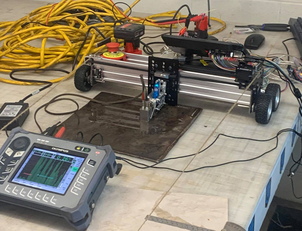
Final Prototype 
Final Model 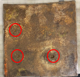
Sample Plate 1 
Olympus Epoch 600 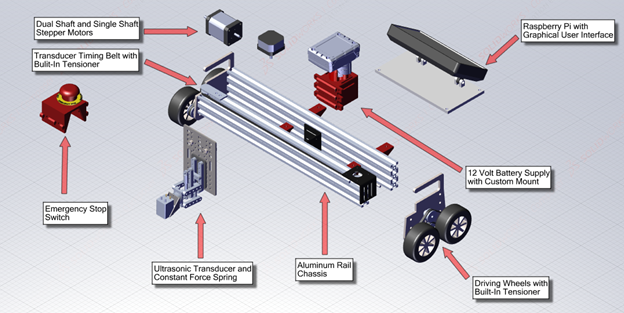
Exploded View 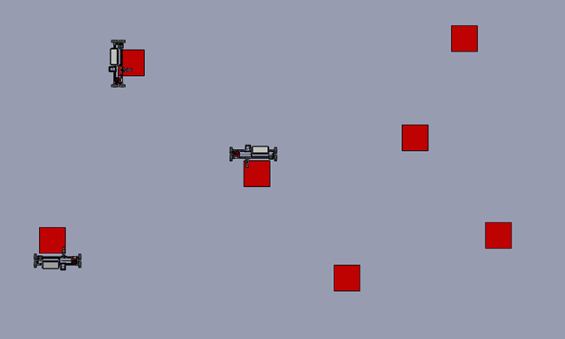
3 Devices Running Animation 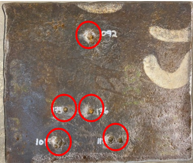
Sample Plate 2 
Accuracy Testing Infographic 
Solidworks Drop Test 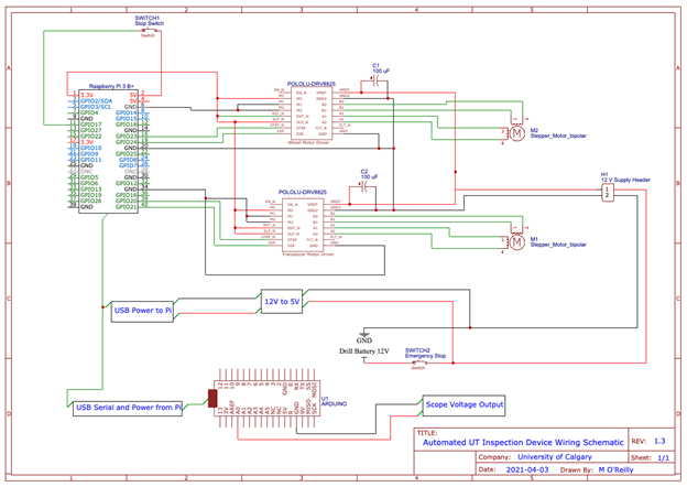
Wiring Diagram 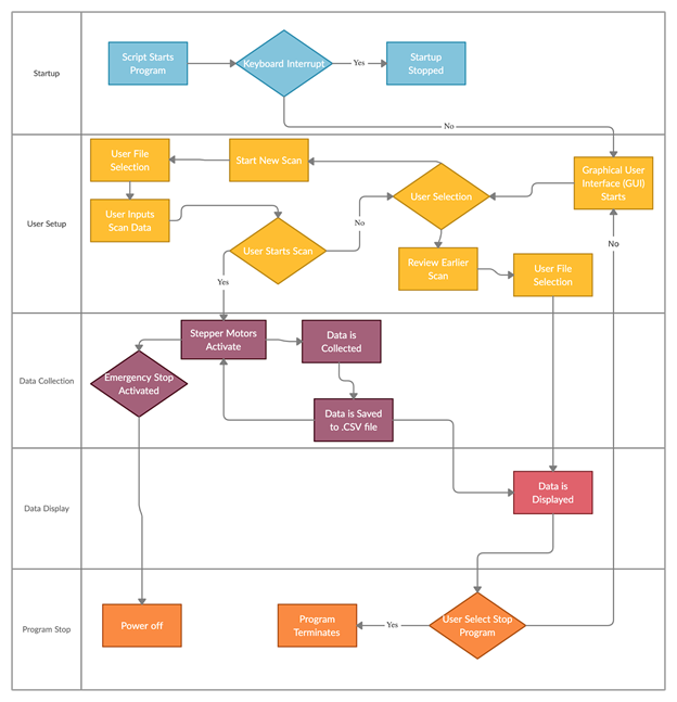
Process Flowchart 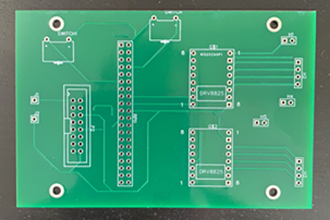
Custom PCB 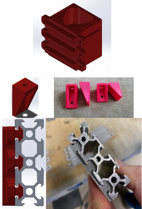
3D Printing Interations 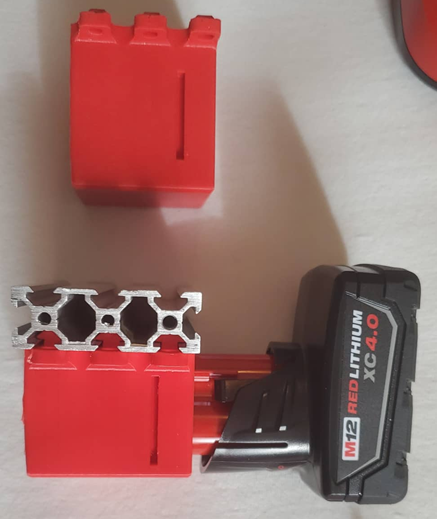
Custom 3D Printed Battery Mounts 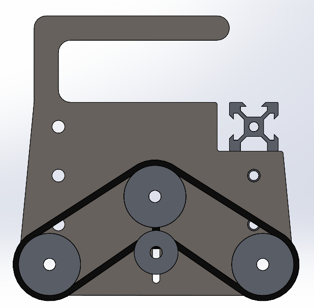
Wheel Belt System 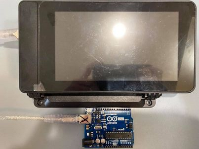
Raspberry Pi Touchscreen and Arduino 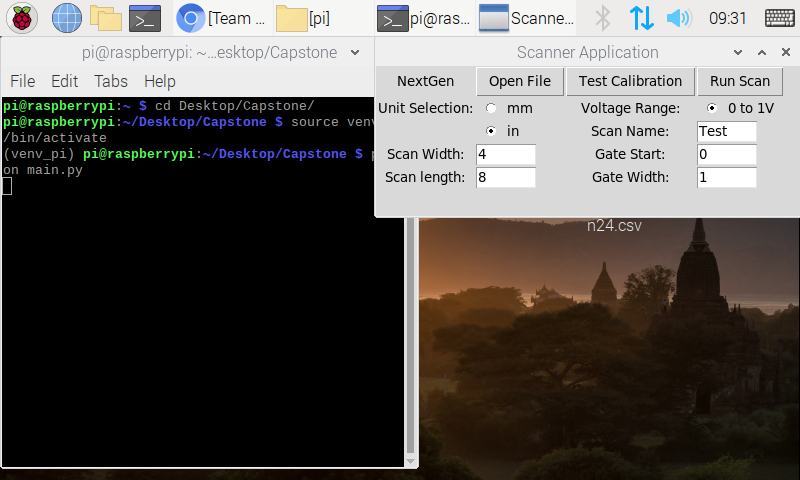
GUI on Raspberry Pi 
GUI on MacOS 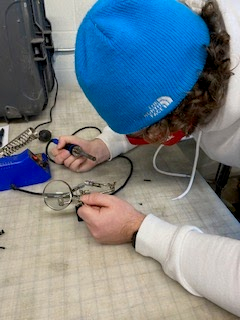
Chase Soldering 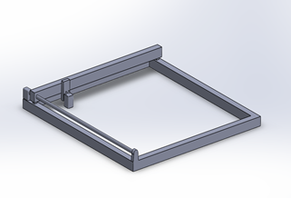
Square Design 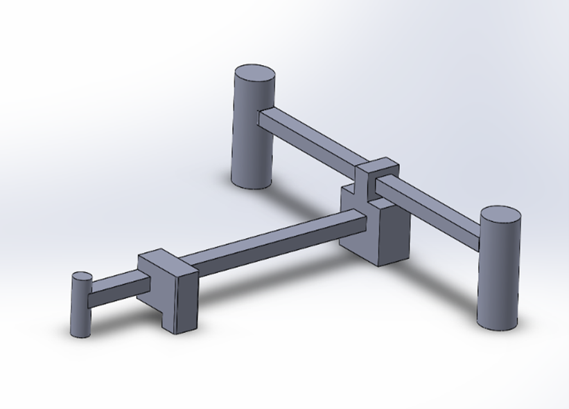
Cross Design 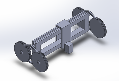
Roller Design 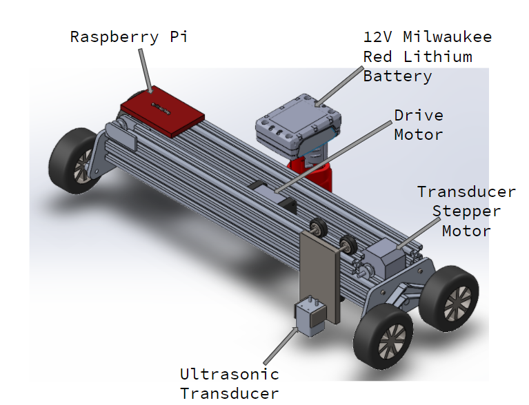
Fall 2020 Model 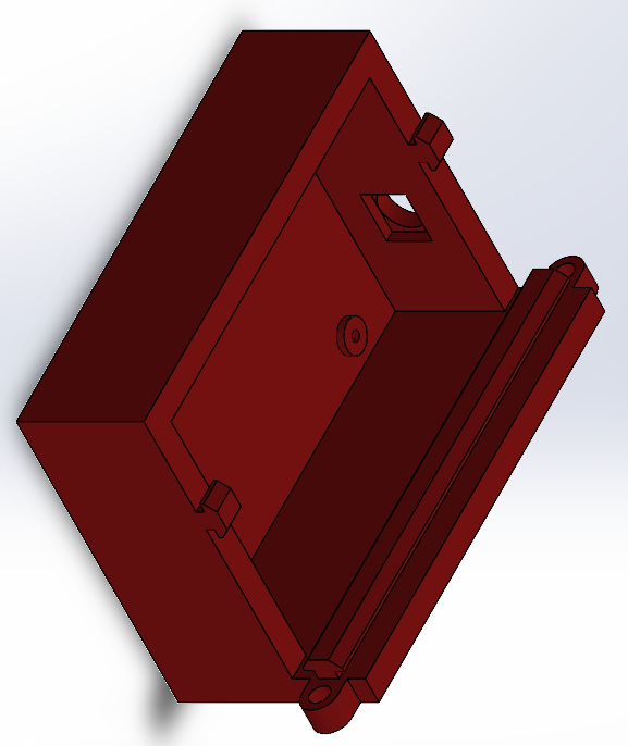
Custom PCB Mount 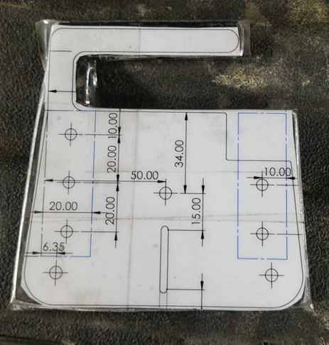
Side Piece Fabrication 1 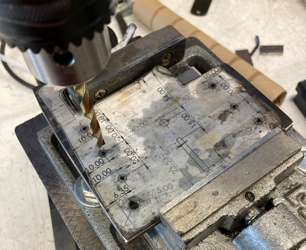
Side Piece Fabrication 2 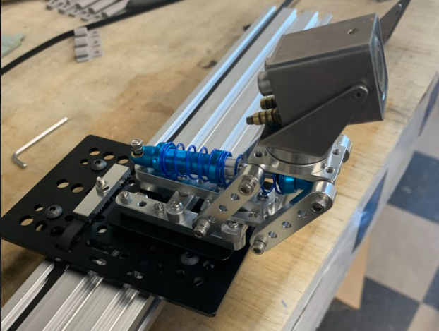
Constant Force Spring With Probe 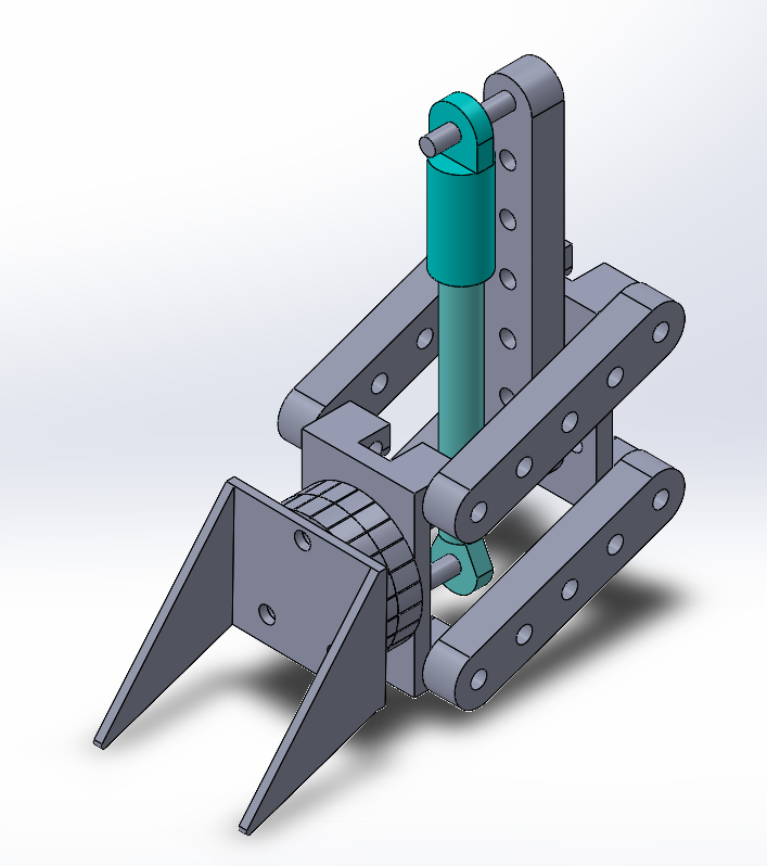
Constant Force Spring CAD Model 
Constructing the Prototype 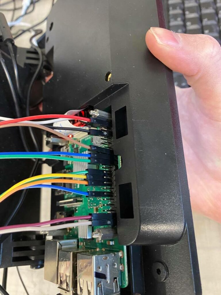
Raspberry Pi Closeup 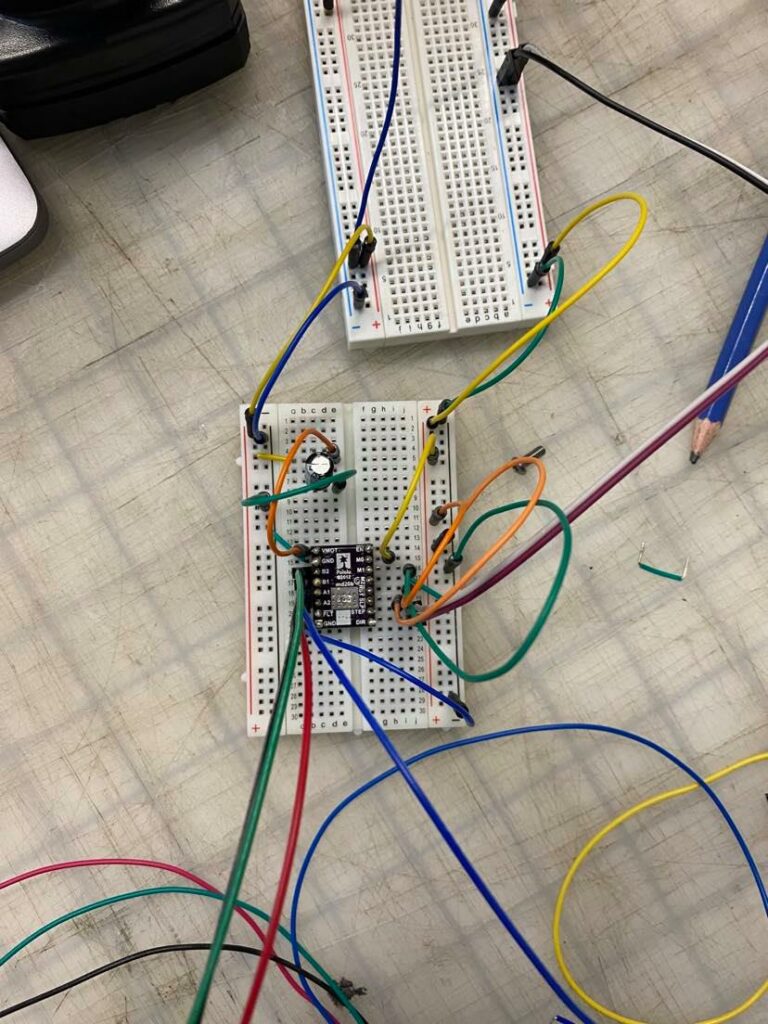
Driver Testing 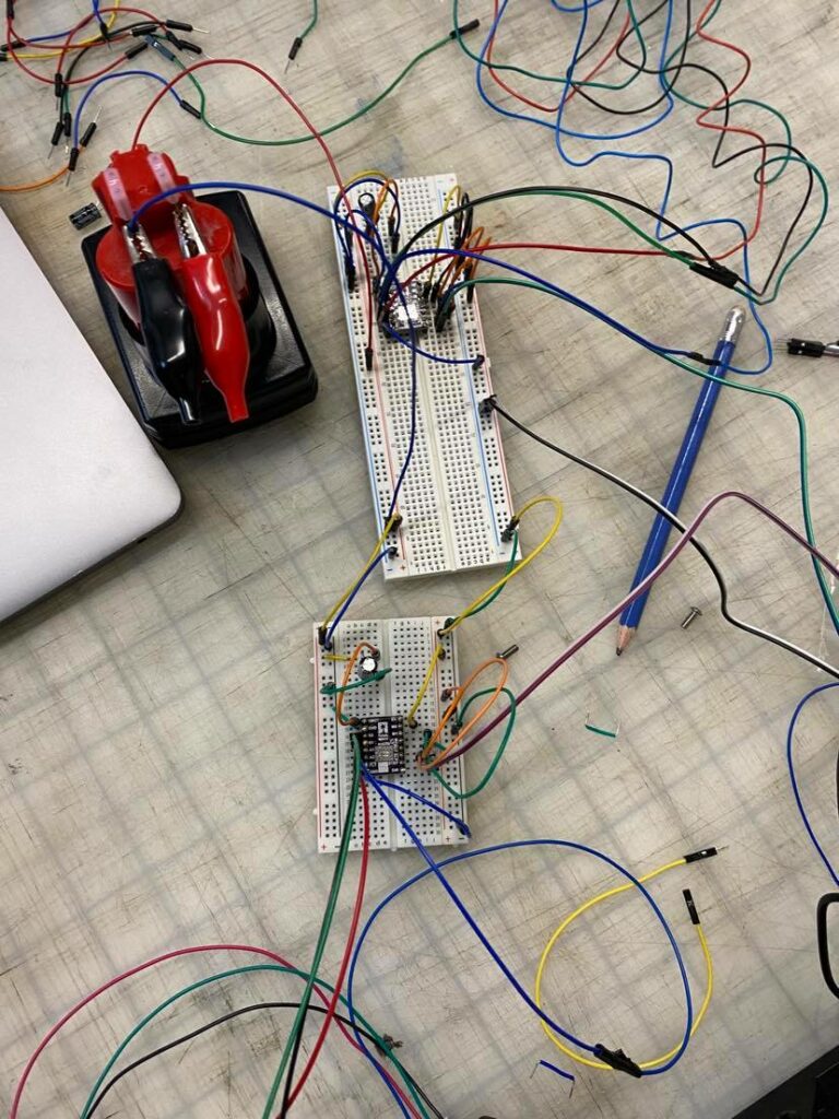
Electrical System Development 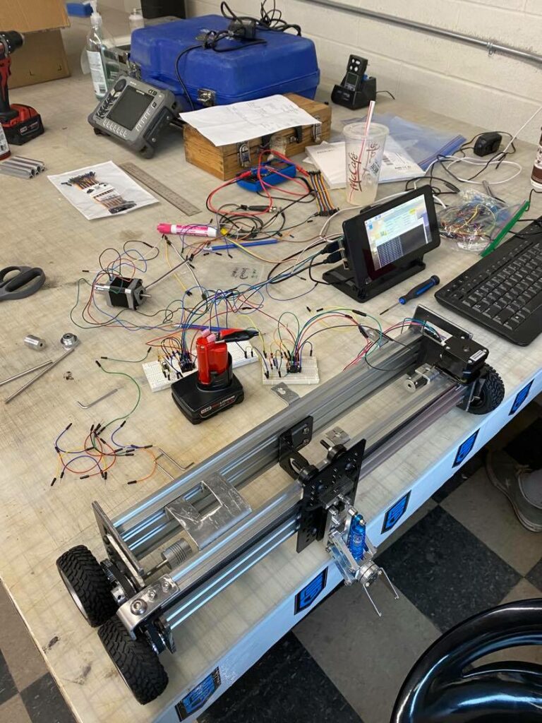
Prototype Development 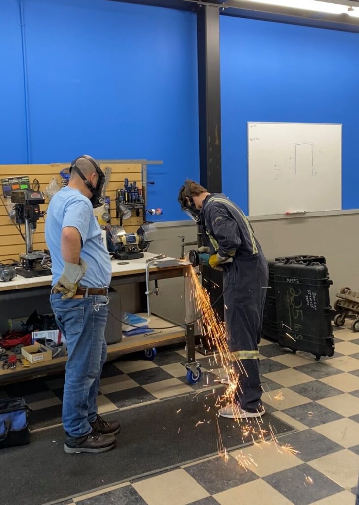
Fabrication 
Testing Setup 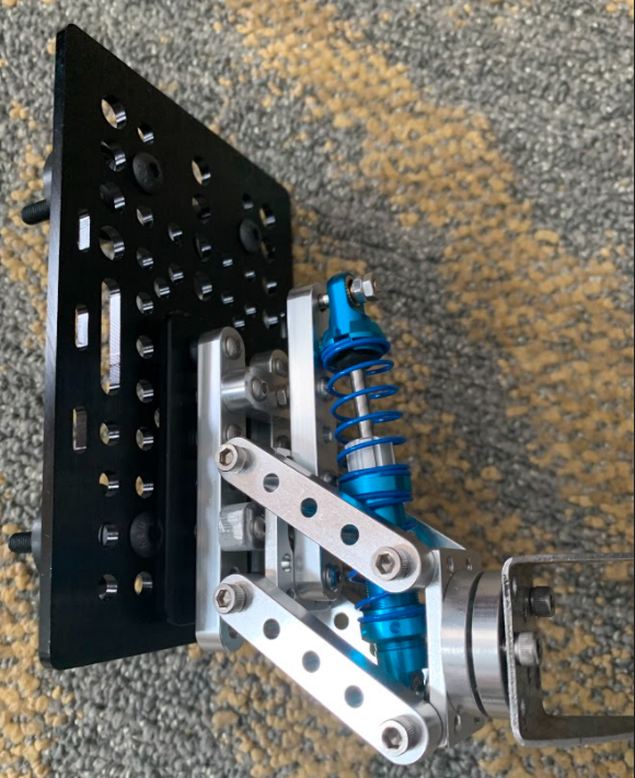
Constant Force Spring without Probe
