Project Category: Mechanical
Join our presentation
About our project
Unmanned aerial vehicles, abbreviated as UAV, are aircrafts that do not require a human pilot onboard, making them suitable for applications in surveillance, military, or missions deemed too dangerous for humans. Our project aims to develop a supersonic UAV named MUFASA for its second design iteration.
MUFASA is a high-speed UAV that had its first design iteration developed in 2019 – 2020. Our project focuses on developing tools and conducting studies to:
- Improve the accuracy of the analysis done on MUFASA to gain better confidence on our results.
- Improve the design process of developing a supersonic UAV.
- Improve MUFASA’s flight performance for Version 2 (V2).
MUFASA V2 will be defined parametrically through SUAVE, a Python module consisting of analysis tools made specifically for aircraft design. Using SUAVE, our team will explore several aspects of aircraft design to meet our goals. These include center of gravity, wing bending, propulsion, sensitivity, and takeoff configuration. Flight performance metrics such as speeds, ranges, and fuel efficiency will be compared with the first design iteration to quantify the merits of our design.
Meet our team members

Cameron Kohlman

Joshia Lee

Joshua Arpon

Ricardo Tovar

Riley Corrigan

Yinka Kehinde
Details about our design
OVERVIEW
We explored different aspects of aircraft design to fully define MUFASA. These include center of gravity (CG), wing bending, propulsion, sensitivity, and takeoff configuration.
Center of Gravity
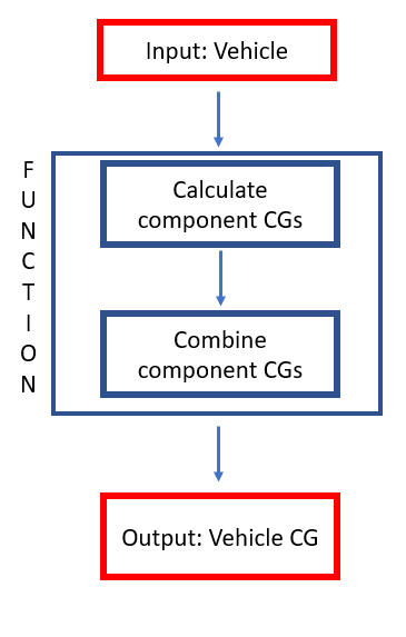
For the CG analysis, we developed a tool that calculates an aircraft’s center of gravity. The CG is calculated by determining the centroids of each of MUFASA’s components (e.g., wings, fuselage, fuel storage, etc.) and combining them to output the aircraft CG. Additional features were also implemented onto this tool. It can calculate the CG when a payload of a given mass is applied, and it can calculate the CG depending on how much fuel is left within MUFASA.
Determining the CG is important because if its CG moves behind the neutral point, then MUFASA may experience instabilities (pitching) when affected by disturbances during flight.
Wing Bending
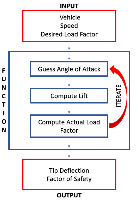
We developed a tool that determines how much MUFASA’s wings bend given a load. Using the Vortex Lattice Method (VLM), the lift distribution across MUFASA’s wings was determined. With this distribution and a given load factor, we iterated through angles of attack and determined the proper angle that gives the input load factor. We then calculated the root moment and the tip deflection that occurs due to the load.
Quantifying how much MUFASA’s wings will bend during flight gives us insight to the structural integrity of the wings. If the wings deflect too much, then changes to the wings’ geometry and rigidity need to be made.
Propulsion
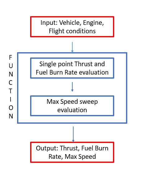
Our propulsion study focused on comparing two types of engines: turbojets and ramjets. These two engines were compared through their thrust, fuel burn rate, speed, and range. Additionally, the specific impulse, which is the measure of how efficiently an engine produces thrust by burning fuel, was compared for the two engines. This study gives us insight on which engine is the ideal engine for MUFASA.
Sensitivity
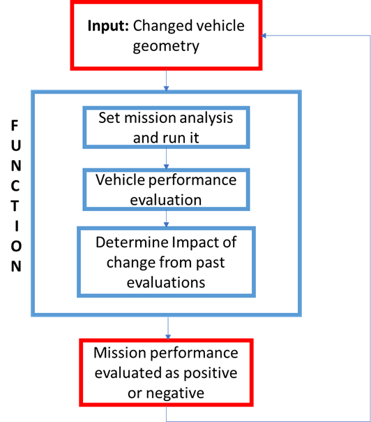
Our sensitivity study involves analyzing how much our performance metrics change given incremental changes on independent variables. In this study, the independent variables we modified focuses on wing parameters. The wingspan, root chord, and taper ratio were increased from 1% to 5% of their original measurements, and the effects of these changes were observed through the following flight characteristics: takeoff distance, speed, and range.
Takeoff Configuration
Our takeoff configuration study compares two takeoff methods: landing gears vs launch lugs. Landing gears act as a suspension system for an aircraft, absorbing and dissipating the kinetic energy that the aircraft experiences. A launch lug is a small protruding solid that is attached onto the aircraft’s fuselage, and this solid is inserted into a launch rail to stabilize the aircraft during takeoff. The benefits and drawbacks of using each configuration were assessed through MUFASA’s speed, drag, takeoff distance, and range. Additionally, the cost and manufacturability of each configuration were considered.
We explored different aspects of aircraft design to fully define MUFASA. These include center of gravity (CG), wing bending, propulsion, sensitivity, and takeoff configuration.
HOW IS OUR DESIGN AN IMPROVEMENT
The improvements our tools and studies provide fall under one or more of the following categories.
- They streamline the conceptual design process.
- They improve upon the accuracy of the previous analyses done.
- They introduce a new aspect of the aircraft that is helpful to be analyzed.
A lot of the Python scripts we created fall under the first point. The CG and wing bending functions allow the conceptual design stage to be more streamlined. Alternative methods of analyses are laborious. For instance, SolidWorks and ANSYS models can be used to determine MUFASA’s CG and stress distribution, but making these models require a considerable amount of effort. The Python structure offered by our functions allow for easy re-calculations to MUFASA whenever geometry modifications are made.
Most of our work falls under the third and last point. The propulsion, sensitivity, and takeoff studies offer new ideas that were not explored back in V1’s conceptual design stage. For the propulsion study, we analyzed ramjets as a potential engine because of their suitability for supersonic flights; ramjets were never considered for V1. Moreover, a sensitivity analysis was never conducted during V1, and using a launch lug as MUFASA’s takeoff mechanism is a consideration exclusive to V2.
SPECIFICATIONS
We acquired our major specifications through our exploration of MUFASA’s center of gravity, wing bending, propulsion, sensitivity, and landing gear/launch lug configuration. These specifications are presented below.
Table 1: MUFASA’s Major Specifications
| Parameter | Specification |
| Fuselage Length | 2.1 m |
| Wingspan | 1.07 m |
| Root Chord | 1.25 m |
| Taper Ratio | 0.072 |
| Takeoff Weight | 53 kg |
| Center of Gravity from the nose | 1.09 m |
| Wing Bending Inertia | 17.9 cm4 (Hollow); 171 cm4 (Solid) |
| Tip Deflection at 6g Load | 3.06 mm (Hollow); 0.32 mm (Solid) |
| Engine Model | Turbojet: AMT Nike Jet Engine |
| Fuel Type | JP8 |
| Maximum Thrust | 675 N |
| Fuel Burn Rate at Maximum Thrust | 0.033 kg/s |
| Maximum Speed | 336 m/s |
| Maximum Range | 319 km |
| Takeoff Speed | 49 m/s |
| Takeoff Distance | 145 m |
| Landing Gear/Launch Lug Configuration | Tricycle Retractable Landing Gear |
HOW WE VALIDATED OUR DESIGN SOLUTION
To validate our design solution, we simulated MUFASA throughout a flight mission using SUAVE. This mission includes the takeoff, climb, cruise, and descent segments of the flight. Note that MUFASA climbs to an altitude of 10 km to reach its cruise segment.
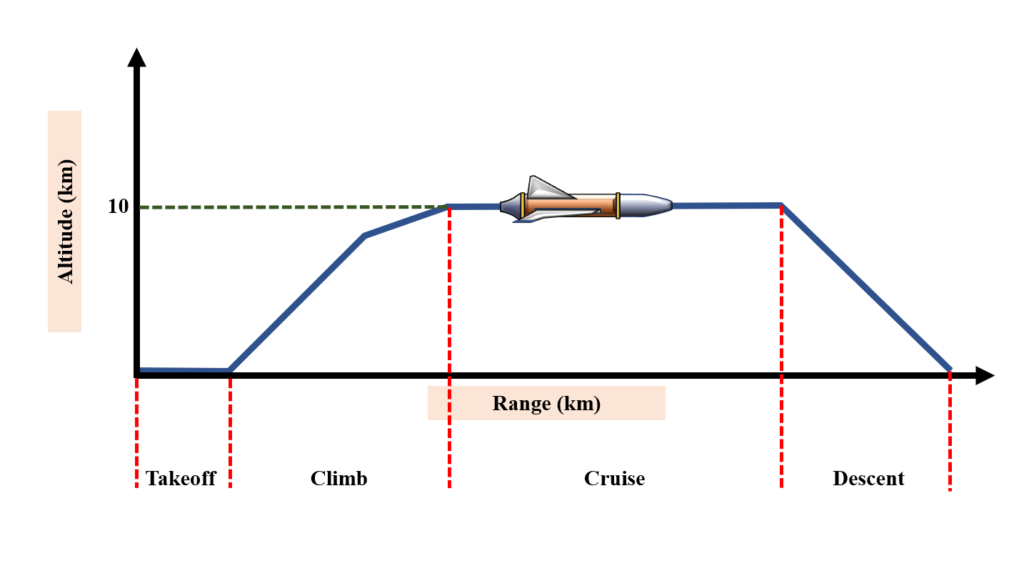
Figure 1: MUFASA’s Flight Mission Divided into Segments
With our mission simulation, we acquired numerous values presented in the Specifications section: takeoff distance, takeoff speed, maximum range and speed, maximum thrust and fuel burn rate, etc. We compared the values from our conceptual build to the values from MUFASA V1 to assess the improvements. These are listed below.
- The specific impulse (thrust-to-fuel burn rate efficiency) increased by 19%.
- MUFASA V2 is 348% faster than V1.
- MUFASA V2’s maximum range increased by 1040% from V1.
- MUFASA’s takeoff distance decreased by 67% for V2.
Additionally, we validated the integrity of our wings through our wing bending study. We subjected MUFASA to the typical loads it would experience during flight and determined how much the wings would be affected under these loads.
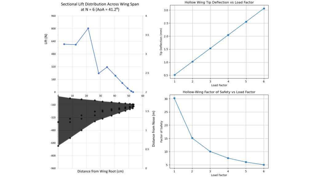
Figure 2: Sectional lift distribution across the wing (top left); Wing geometry broken into sections (bottom left); Hollow wing tip deflection (top right); Hollow wing factor of safety (bottom right)
From our studies, we determined that MUFASA V2 would have a tip deflection of no more than 3.06mm when subject to a 6g load, with a factor of safety of 5. The resulting tip deflection is less than 0.3% of the wingspan, indicating there will be minimal impact to the vehicle’s aerodynamics up to a 6g load. The results of our wing bending study confirmed that the MUFASA V2 wings are more than capable of withstanding all anticipated loading.
By simulating MUFASA throughout a flight mission, we determined its flight characteristics. These results quantify how much the changes we made improved MUFASA V1. Beyond the performance improvements, these simulations also shed light onto the structural integrity of our conceptual build. It provides assurance that MUFASA will not fail under the loads of supersonic flight.
Partners and mentors
We want to thank everyone who helped us with this project. Our project sponsor Dr. Craig Johansen, AERO-CORE members Ben Dalman and Shaun Gair, as well as the rest of the AERO-CORE team. Their guidance and knowledge has been invaluable.
Our photo gallery
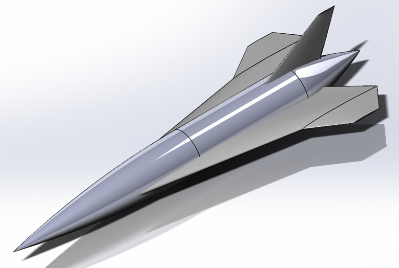
Preliminary UAV Design (S. Gair et al. (2020)) 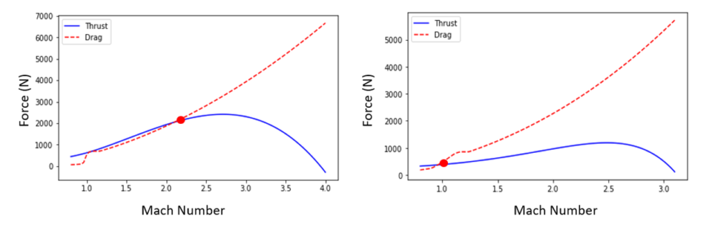
Left: Thrust and Drag vs Mach Number for Ramjet
Right: Thrust and Drag vs Mach Number for Turbojet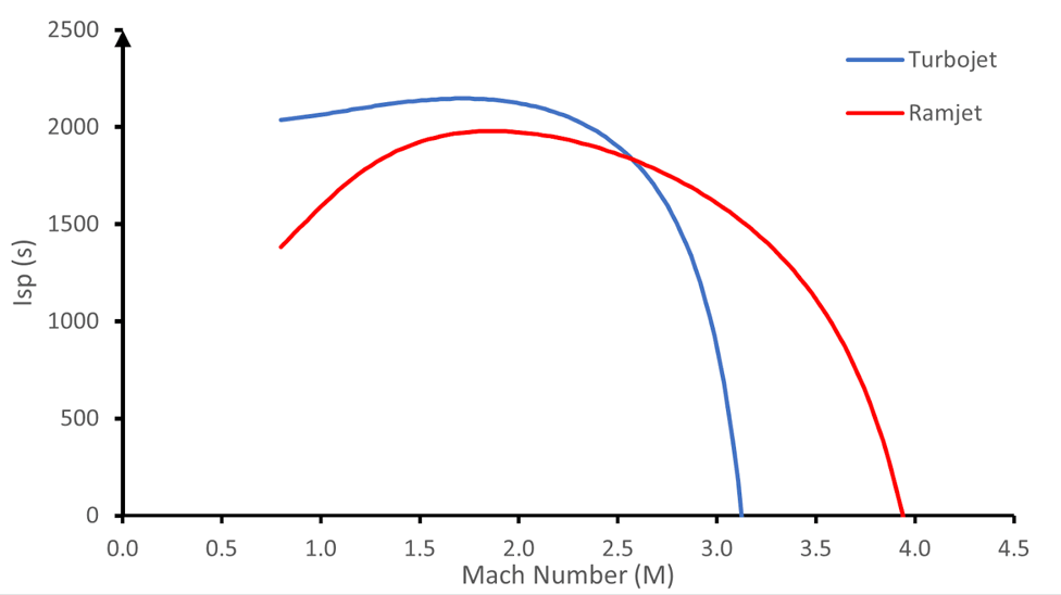
Specific Impulse Graph for Turbojet and Ramjet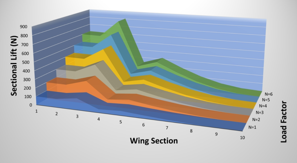
Lift Across Wings Based on Varying Load Factors 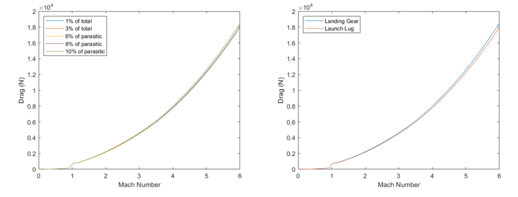
Left: Landing Gear Drag Contributions
Right: Launch Lug Drag Compared to Landing Gear Drag
