Project Category: Mechanical
Join Our Presentation
About Our Project
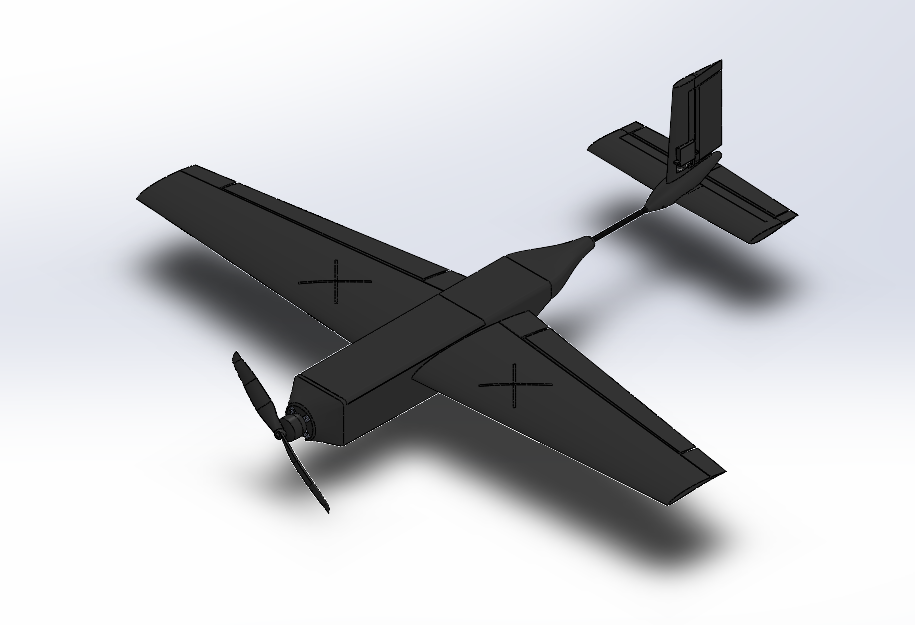
The goal of this project was to design a small-scale fixed-wing unmanned aerial vehicle (UAV) based on a previous UAV developed by our project sponsor, Dr. Schuyler Hinman. The aerodynamics of small-scale airplane components can be analyzed with the UAV for research purposes. The previous UAV developed by Dr. Hinman worked well as a glider but had issues with the control system; therefore, this project aimed to design a more robust control system while keeping the original wing shape. In addition to improving the control system, manufacturing techniques and building materials were explored to ensure rapid prototyping. The assembly was carefully considered to create a modular design whose parts could be swapped.
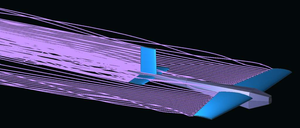
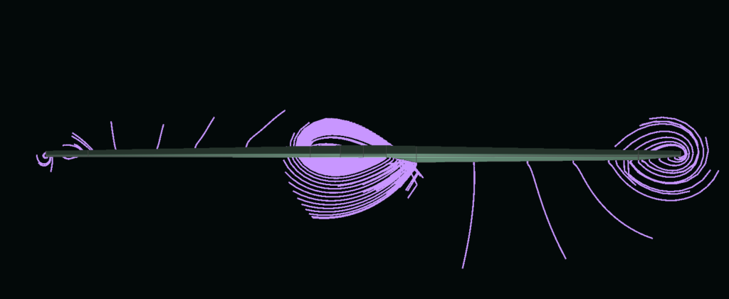
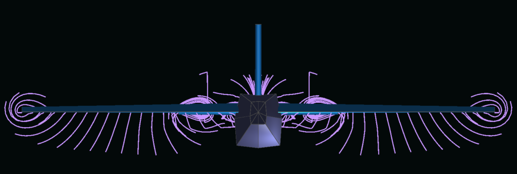
Analysis tools to complete this design included XFLR5 and CFD for aerodynamic analysis, MotoCalc for propulsion system calculations, and SolidWorks for 3D modelling, placement of the center of gravity, and finding the moment of inertia for control surface sizing calculations.
Budget: $500.00 CAD
Further information can be found in the video link below.
Meet Our Team Members

Aerodynamic Analysis
Computational Fluid Dynamics

Aerodynamic Analysis
Control System Design

Propulsion System
Fuselage Design

Internal Structure Design
Manufacturing Lead

Project Management
Control System Design
Details About Our Design
How Our Design Addresses Practical Issues
Aerodynamic experimentation is often done with wind tunnel testing, which can be expensive. There are many programs to perform aerodynamic analysis via simulation; however, physical testing may shed light on some problems not covered by simulation. Our small-scale UAV is meant for physical testing of new aerodynamic concepts such as the use of flaperons, unique airfoil shapes, or the outboard horizontal stabilizer on a tailplane.
What Makes Our Design Innovative
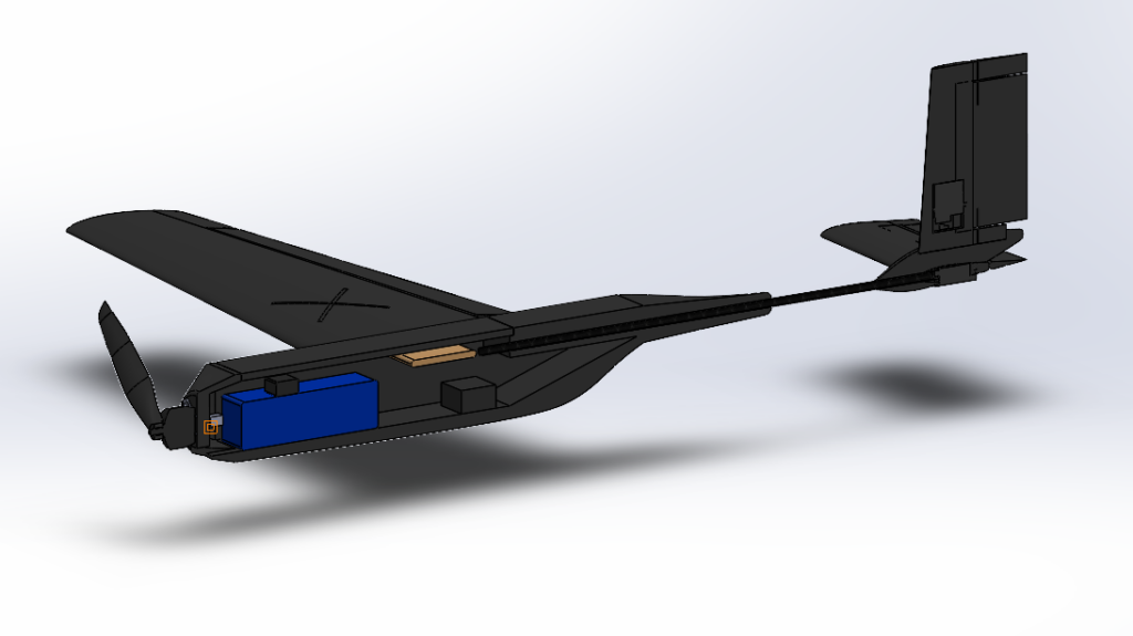
Our design is meant for rapid prototyping and modularity. It is innovative because it uses a non-conventional 3D printing material called Light Weight PLA (LW-PLA) along with other materials to ensure our plane is as light and strong as possible and can be manufactured quickly. Along with LW-PLA, we use a conventional RC airplane material, balsa wood, as a supporting structure due to its high strength to weight ratio. Finally, we use a carbon fiber rod that connects the tail to the fuselage. Our design is meant to be modular so that the plane can be assembled and disassembled easily, with the possibility to swap out wing and tail shapes.
What Makes Our Design Solution Effective
The design solution is effective because, with the 3D modelled files, Dr. Hinman can simply print or modify components as he sees fit. The internal structure will remain the same, but with different wings or tail stabilizers, the aerodynamics will change drastically. He can then compare his simulated results with physical testing using our UAV.
How We Validated Our Design Solution
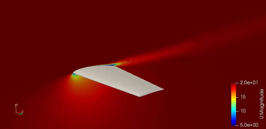
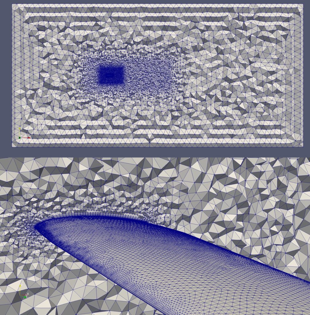
Our design has been carefully researched and has undergone extensive analysis by simulating the aerodynamics, analyzing the propulsion system, completing strength calculations, and analyzing the control system. With the software XFLR5, the preliminary aerodynamic analysis was completed. This gave us lift and drag coefficients, target speeds, and a target weight for our aircraft given the wing shape. Another software, MotoCalc, was used to determine flight performance using different combinations of marketed propellers and motors. Using the simulated results from XFLR5, an appropriate propulsion system was selected for the achievable flight characteristics. For further validation of our design, CFD has been completed. SolidWorks was used to model the aircraft where the center of gravity was calculated and strategically placed. Moments of inertia were calculated from the 3D model which allowed us to appropriately size our control surfaces and select servo with the required torque.
Feasibility Of Our Design Solution
Our design solution is entirely feasible and is projected to cost less than the allotted budget of $500. The plane can be manufactured with any 3D printer, and the remaining materials are accessible through local hobby shops.
Partners and Mentors
Thank you to Dr. Schuyler Hinman, our project sponsor and academic advisor, for his constant guidance and mentorship throughout this project. Also, we would like to thank Shaun Gair for sharing his expertise in wind tunnel testing and 3D printing with LW-PLA.
Our Photo Gallery


References
- Capable Computing Inc. (2021). MotoCalc 8.
- E168 (12.45%) – Eppler E168 low Reynolds number airfoil Airfoil Tools. Retrieved September 20, 2021, from http://airfoiltools.com/airfoil/details?airfoil=e168-il
- Hinman, W. S. (2013). Final design report. University of Calgary.
- Kim, K., Moskowitz., H., Shin., Jong-Seok (1997) Design Decomposition in Quality Function Deployment. Essays in Decision Making.
- Lennon, A. (1996). Basics of R/C model aircraft design. Motorbooks Intl.
- Martínez, Miguel & Marquez, Rafael & Luengas, Oswaldo & Martínez, Oscar & Clamens, Andrés. “2020 SAE Aero Design East Design Report” Universidad Metropolitana, Apr. 2020, pp. 1-31
- Megson, T.H.G. (2013). Aircraft structures for engineering students (5th ed.) (figure 14.7). Elsevier Ltd.
- Miller, Corbin & Perleberg, Eli & Simmons, Zach. “NAU Mechanical Engineering Senior Capstone SAE Aero Micro Design Final Report” Northern Arizona University, 1 May. ___2020, pp. 1-55
- Robertson, C. (n.d.). cr001sm – Cody Robertson CR 001 R/C hand-launch low Reynolds number airfoil (smoothed). Airfoil Tools. Retrieved September 20, 2021, from http://airfoiltools.com/airfoil/details?airfoil=cr001sm-il.
- Tail Designs. What-When-How. Retrieved December 9, 2021, from http://what-when-how.com/flight/tail-designs/
- Wittwer, J. (2021). “Gantt Chart Template for Excel,” Vertex42.com. [Online]. Available: https://www.vertex42.com/ExcelTemplates/excel-gantt-chart.html. [Accessed: 28-Oct-2022].
- XFLR5: Analysis of foils and wings operating at low Reynolds numbers. (2009). Purdue University.
