Project Category: Mechanical
Join Our Presentation
About Our Project
The High-speed Vehicle Automated Spoiler project was focused on providing drivers with greater maneuverability and confidence over their vehicle when in a performance-oriented setting. We intended to conceptualize, design, and prototype an active spoiler that would use a combination of aerodynamic concepts, dynamic principles, and the knowledge we learned throughout our engineering experience. Additionally, to challenge ourselves we attempted to automate the spoiler angle in conjunction with determining the intricacies of the extension/retraction mechanism, as well as, designing a new airfoil based on extensive research. Air brake assistance would be a key design function for the aforementioned as it utilizes the underlying control system/sensors to maximize the downforce design features of the airfoil.
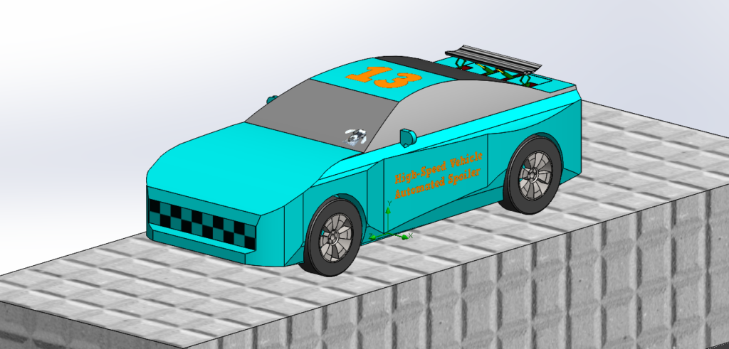
The project was divided into three sections which focused on the airfoil design, mechanism, and control system. Through an iterative process, the design of the active spoiler improved, yielding greater overall vehicle performance. An R35 GTR was the vehicle model selected to test and analyze the active spoiler.
Meet Our Team Members


Details About Our Design
What is an Automated (active) spoiler?
Active spoilers have integrated mechanisms capable of retracting/extending and have the option of varying the angle of attack. The majority of conventional spoilers are designed with a fixed angle of attack. Having a fixed angle of attack limits a vehicle’s capability of being efficient throughout a velocity range as an optimal downforce can not be maintained. Having the ability to change aerodynamic factors such as height and angle of attack allows us to vary the downforce, in turn allowing for more optimal efficiency. Besides greater vehicle performance, safety is another added benefit to active spoilers.
Our Design Features (All Automatic)
Extension and Retraction
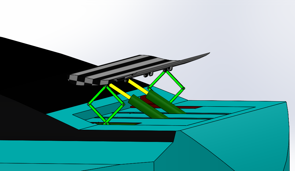
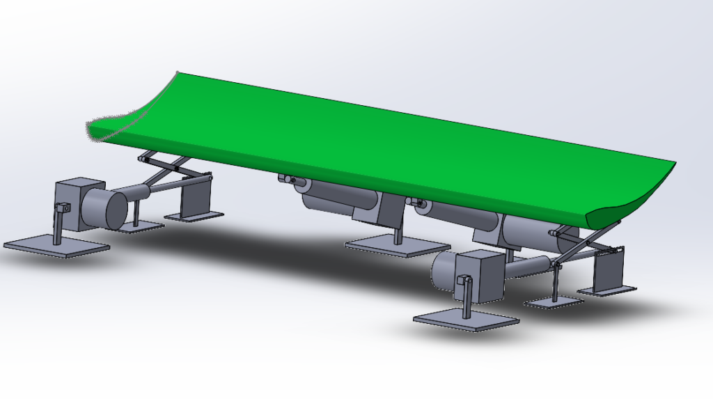
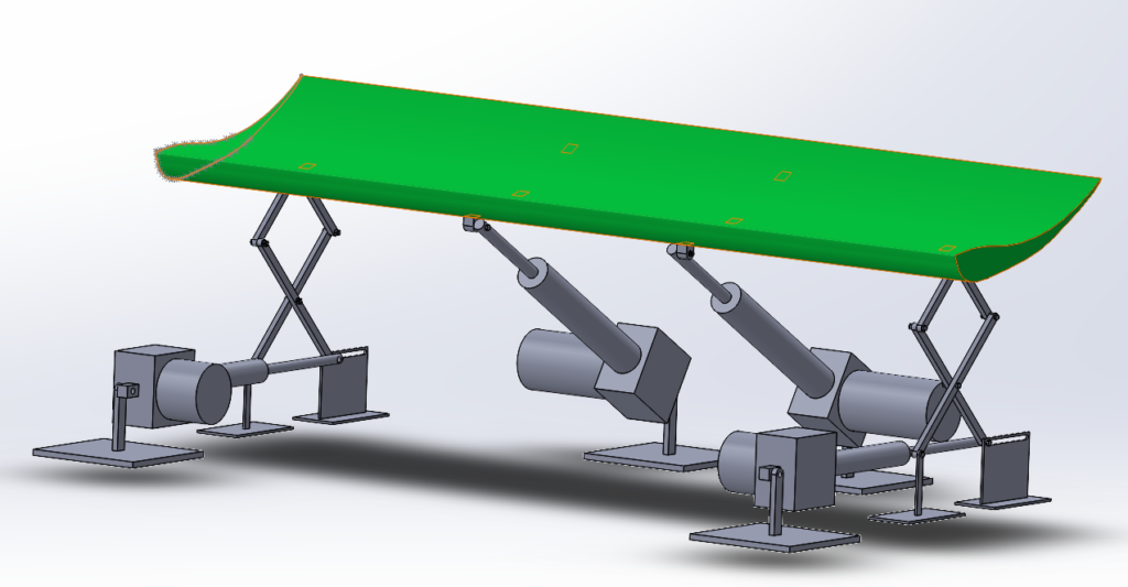
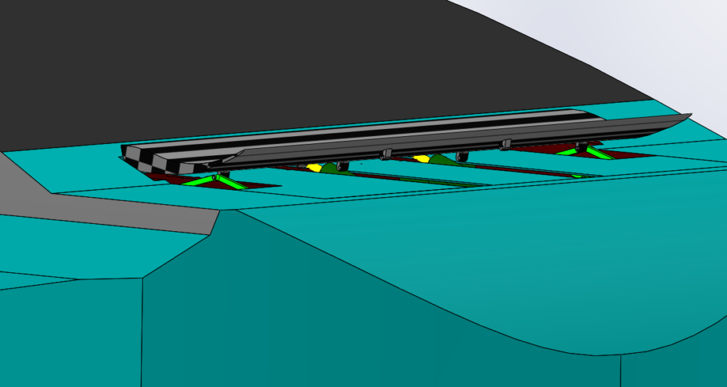
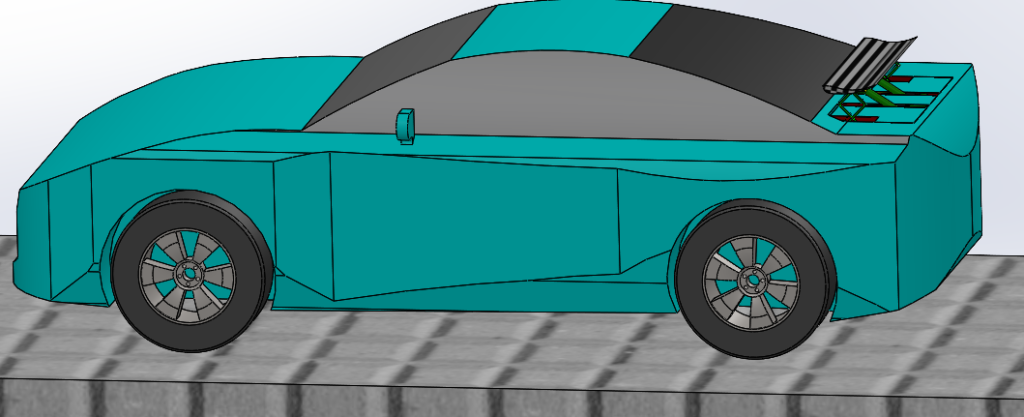
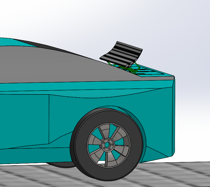
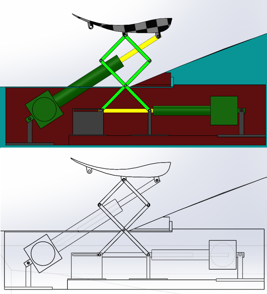
Our intricate scissor-lift mechanism is designed to extend and retract the spoiler through the use of linear actuators. The spoiler will extend out of the trunk cavity in approximately 2.2 seconds when the vehicle has achieved a speed greater than 100 km/h. A spoiler is not beneficial at lower speeds and as such the mechanism will retract when the vehicle is cruising at speeds below 100 km/h.
Automatically Changing Angle of Attack
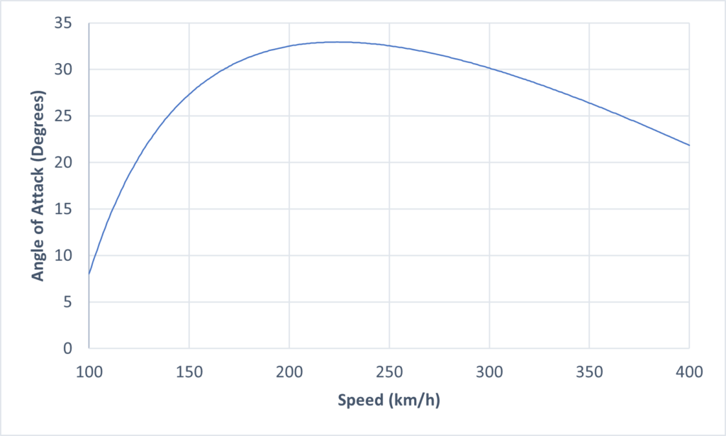
Another key feature of our project includes adjusting the angle of attack with the aid of a control system. While the vehicle’s speed is between 100 km/h and 400 km/h, the control system will output a signal to the linear actuators located in the middle to automatically adjust the spoiler’s angle of attack based on the current speed. As the spoiler’s angle of attack is altered, it changes the amount of downforce the vehicle experiences. At higher speeds, the vehicle will require greater downforce to ensure the vehicle has sufficient traction.
Airbrake Mode
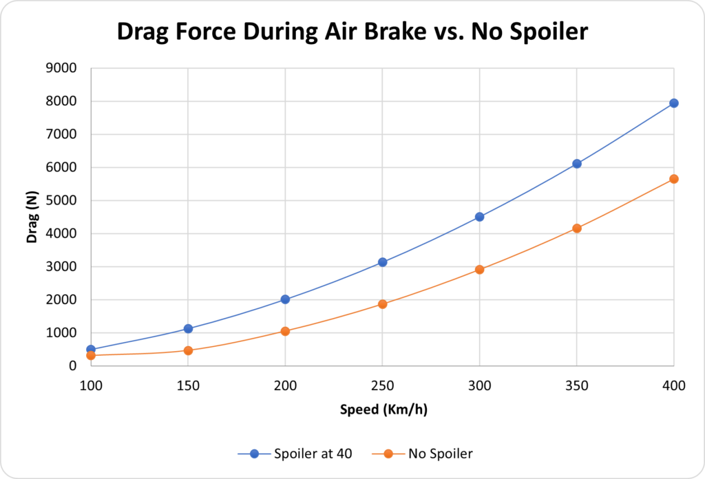
The airbrake assistance will allow for sudden braking by adjusting the angle of attack of the spoiler to 40 degrees and achieving maximum drag when pertaining deceleration requirements are met.
How is our design an improvement?
- Our design allows for the angle of attack to remain optimal throughout the vehicle’s velocity range rather than stay fixed. This capitalizes on the aerodynamic features capability of generating downforce and drag, ensuring it is as efficient as possible. This would provide the vehicle operator with an added level of maneuverability and stability meaning they have the confidence of having traction. Varying the angle of the attack directly impacts the vehicle’s generation of downforce and drag.
- While not being fully utilized, a conventional spoiler will continue to provide drag and downforce which works against the car. Our design allows for the spoiler to be retracted allowing for minimal disturbance to airflow during cruising. This results in less wear on the vehicle’s braking system, and greater fuel efficiency.
- Our Designs brake assistance feature enables a vehicle to have a shorter stopping distance when traveling at speeds above 100 km/h, adding another degree of safety.
How we are measuring the project’s success?
After selecting the final design and configuration, the following deliverables are the measurements of a successful project:
- Final spoiler design must be able to produce enough downforce to counteract lift force up to 400 km/h.
- The final spoiler and mechanism system must be able to handle the stress applied due to downforce at a max speed of 400 km/h (requiring a safety factor of 3).
- Mechanism and control system must be able to deploy within 3 seconds of pertaining conditions being met.
- The control system must adjust the spoiler to an optimal angle of attack (±5% tolerance) to produce the required downforce and obtain optimal traction.
How we validated our design solution?
Specifications:
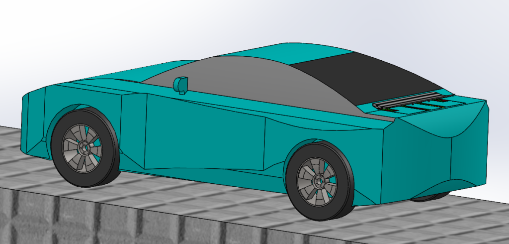
Positioning of the spoiler on the trunk
- All potential orientations of the mechanism were simulated to ensure that there were zero issues associated with mechanical interference.
- The modifications made to the GTR body took into consideration any potential impacts on the structural integrity. The result is the following assembly:
Functional Testing:
Counteract lift up to 400 km/h
- Modulation of the angle of attack of the spoiler to counteract the lift force is one of the most critical aspects of this project. Fluid simulations were performed to determine the ideal downforce required to maintain a constant aerodynamic grip force at varying speeds. This downforce was utilized to determine the required angle of attack as speed varies.
- The following are the results of these simulations:
Performance Testing:
Ability to handle all stresses with safety factor
- A safety factor of 3 was utilized to ensure all stresses can be comfortably withstood by all components of the final design. All relevant simulations were performed at 400 km/h with airbrake mode to maximize the stresses and, and the appropriate materials and actuators were chosen.
- The actuator model chosen was PA-03. With four incorporated into the design, the total stress the system can handle is 3559N (363 kg), which meets the safety factor. Additionally, the materials for the spoiler and mechanism are carbon fiber and mild carbon steel which also satisfy the strength requirements.
Evaluate reaction time for control system to change airfoil to desired angle of attack
- The performance test for the control system consists of the application of all the operating modes in a random sequence. This will test the control system under every potential scenario it can encounter when active, which will in turn evaluate its overall capabilities in terms of response time and accuracy. Simulink was used to model and conduct analysis. The figure below specifies the operating modes to be tested. Regions 1 and 5 are the acceleration zones. Regions 2 and 4 are cruising zones. Regions 3 and 6 are deceleration zones.

- With the scenario above, it was determined that the deployment takes approximately 2.19 seconds and the average reaction time for the control system to settle to an error of +/- 0.2% is 1.8 seconds.
Perform Solidworks CFD simulations to determine the angle at which shortest stopping distance is obtained for brake assistance
- A useful feature of having a modulated spoiler is the ability to air brake. The drag generated during air brake mode aids greatly in halting the vehicle. The angle at which the maximum amount of drag is generated was determined with flow simulations. Intuitively, 45 degrees was understood to be the optimal angle for air braking.
- The optimal angle for air braking was determined to be 40 degrees by computing fluid simulations.
Scenario Testing:
Conduct comparison with a model without the spoiler under different operating modes
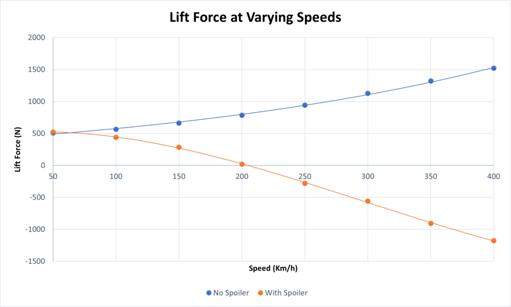
- To test the capabilities of the developed system, it was tested against a stock model of the chosen vehicle to determine how the lift forces were impacted at varying speeds.
Evaluate Brake Assistance effectiveness
- Likewise, the effect of the system while air braking was tested against a stock model of the chosen vehicle.
Partners and Mentors
We would like to thank Dr. Philip Egberts, TA Danny Wong, and Dr. Simon Li for their continuous guidance and feedback throughout the year. We would also like to thank Dr. Peter Goldsmith and Dr. Jeff Pieper for their assistance with the control system. Also, thank you Muhammad Saadan for your contribution to the video.
Our Photo Gallery
PAPA BLESS *PRAYER HANDS*
