Project Category: Mechanical
Join our Presentation
Scheduled for April 13, 2021 from 10:00 AM to 12:30 PM (MST)
About our Project
There is an increasing need for more automated systems within the aviation industry as the production of aircrafts increases annually. Our project sponsor tasked us with designing a six degree of freedom system within certain specifications. Not only did we meet our challenge of creating an assembling robot that satisfies our sponsors certain conditions, but we designed the mechanism to operate more than 20% greater than our requirements in order to ensure its mobility, rigidity and safety.
Our capstone project focused on the kinematic analysis and design of an assembling robot in the aircraft. The process of assembling equipment within an aircraft is currently conducted using a team of four to six individuals, which is proven to be time-consuming, labor-intensive, and increases assembly costs. There is a need in the aircraft industry for a robotic mechanism to automate this process. From this we analyzed and designed a Stewart Parallel mechanism to serve this purpose.
This mechanism follows the main specific design constraints shown below.
- Six degrees of freedom
- Maximum total weight of 18 kilograms
- Load capacity of 100 kilograms
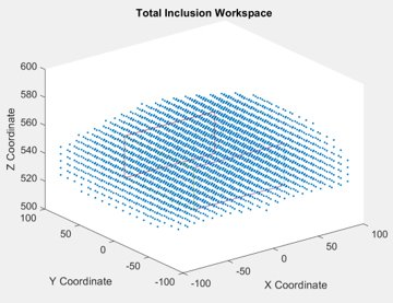
- Operate within a workspace of 100 millimetres in the X, 100 millimetres in the Y, and 30 millimetres in the Z plane.
- Serve rotations about the X and Y axes no less than 5 degrees
The mechanism will assist in the assembly of objects such as passenger seats and carry on storage containers within an aircraft. As previously stated, four to six individuals are required to lift and rotate heavy objects while inserting screws, bolts, and other fasteners where necessary during assembly. Our mechanism will be used in conjunction with a cart system, designed by graduate students from Tianjin University. The Stewart Parallel mechanism will serve the purpose of moving around the aircraft cabin to assist workers with lifting, rotating, and moving objects into place.
Meet our Team Members


Design Process
Kinematic Modeling and Analysis
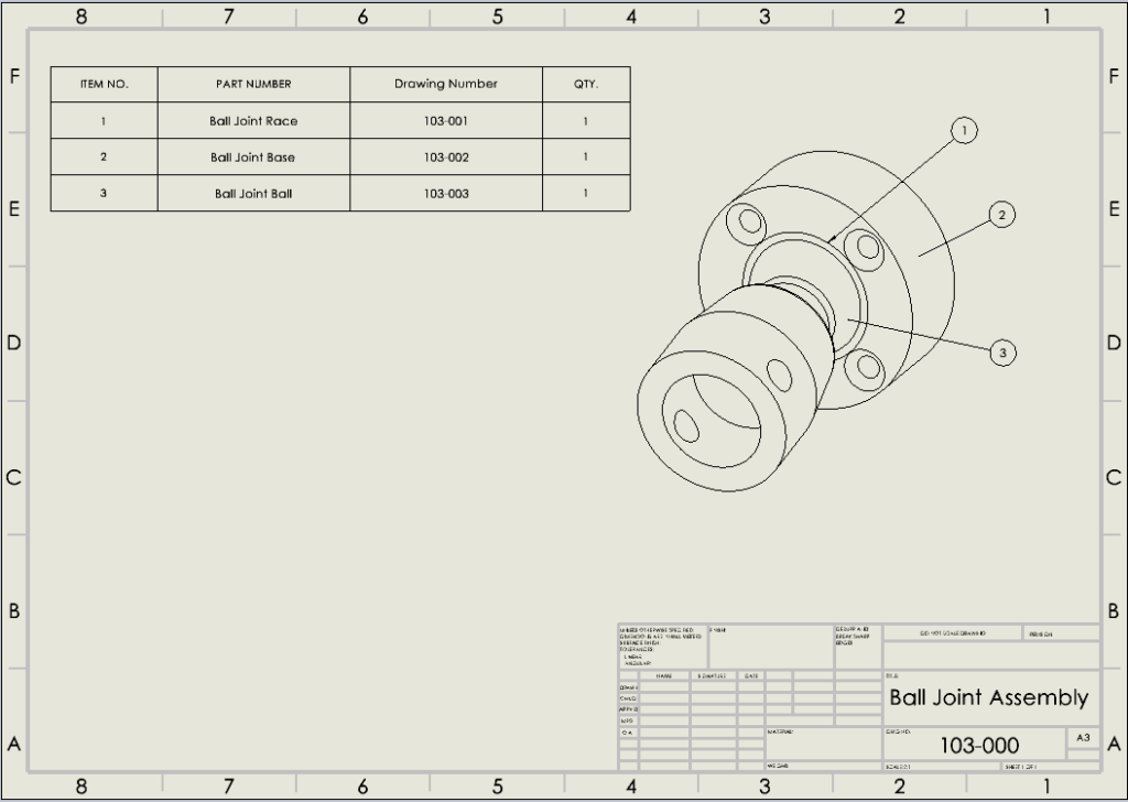
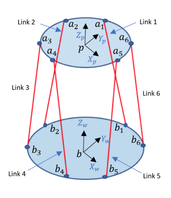
The Stewart Parallel mechanism consists of a base and a platform connected by six actuated links. For the purposes of kinematic analysis, two frames were defined as follows. The reference frame B was defined as Xb, Yb, Zb on the base at point b and the frame P was defined as Xp, Yp, Zp on the platform at point p.
The Stewart Parallel mechanism also consists of six universal joint, six spherical joints, and 6 prismatic joints. The six universal joints labelled b1 – b6 were defined on the base which are connected via the links to six spherical joints labelled a1 – a6 on the platform. Each link connecting to its corresponding joint on the base to the joint on the platform, that is link 1 connecting joint b1 on the base to a1 on the platform, is actuated by a prismatic joint. The figure below shows a visual representation of the frames and joint locations.
Optimal Design with Multi-Objectives
Objective functions of the platform weight and rotation were constructed in MATLAB. MATLAB’s fmincon function takes an objective function and constraints as inputs, and outputs values of the design variables that minimize the objective function.
For our design, we identified the link minimum and maximum lengths, the radii of the platform and base, and the angle between joints as key design parameters. The sponsor requirements were imposed as constraints on these variables; namely, a maximum weight of 18 kg, a minimum platform rotation of 5 degrees about the X and Y axes, and mechanical constraints to avoid solutions that do not fit the design. During the duration of the design process, design variables were set to values identified by the SolidWorks team to further constrain the optimization.
From this process, we gained valuable insights into how software platforms can be utilized for design optimization. A key insight is that optimization must be performed early in the design process; otherwise, its usefulness is limited by design and time constraints. However, the implementation of optimization within our project allowed for us to verify our solutions at each design iteration, which allowed us to obtain our final design that satisfied all design requirements.
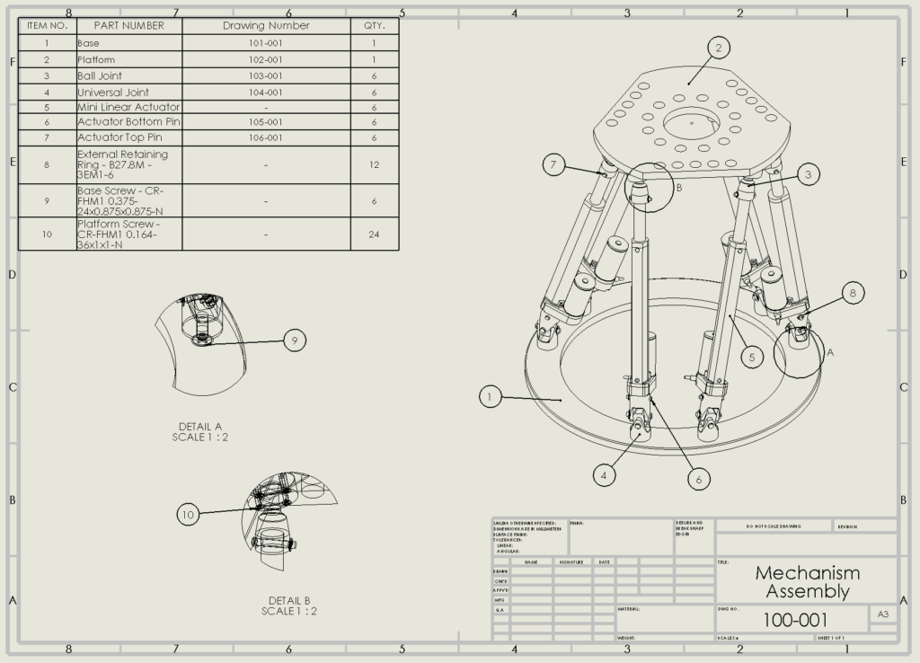
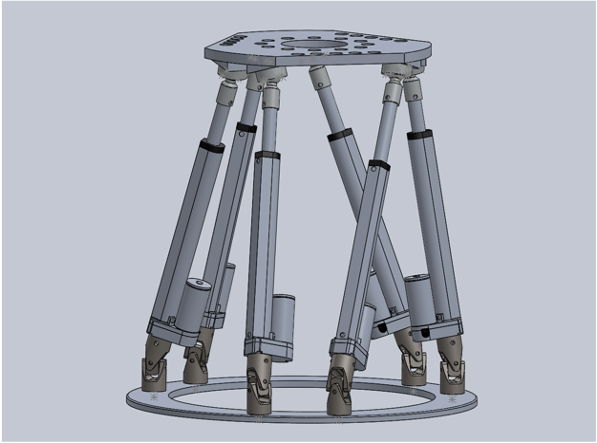
Virtual Prototype Design
By applying the structural parameters resulting from design optimization and a repetitive design process, our virtual prototype of the robotic Stewart Parallel mechanism was created using SolidWorks.
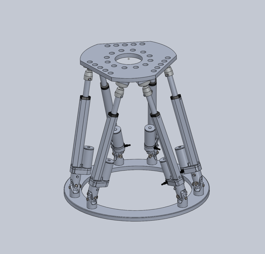
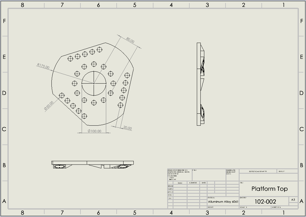
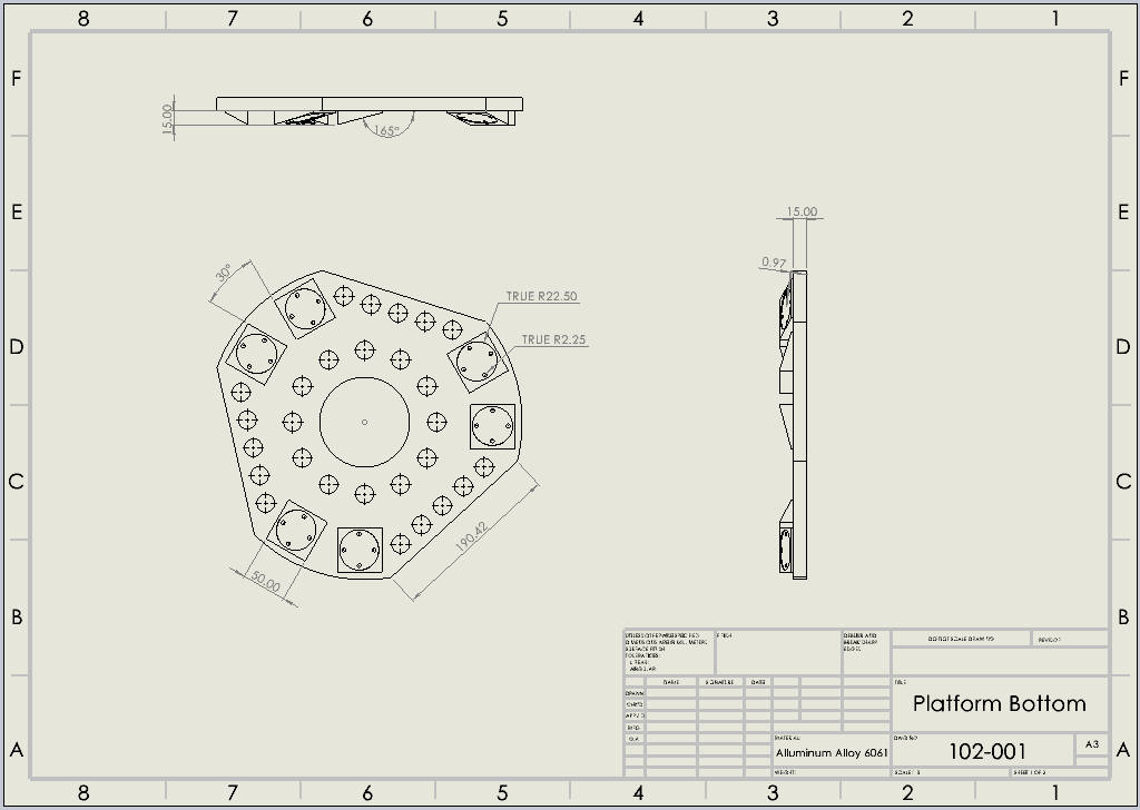
Mechanism Parameters:
Platform Diameter: 350mm
Base Diameter: 525mm
Platform Thickness: 15mm
Base Thickness: 15mm
Home Position: (0,0,540) mm
Weight: 14.54kg
Details About our Design
Design Application
Currently, components inside the aircraft are assembled by four to six individuals that lift the object and insert screws and bolts where necessary. These objects are normally the kitchen unit, passenger seats, and carry-on storage compartments. To ease the workload for these individuals and allow for a more efficient assembly on the aircraft, the use of a Stewart Parallel mechanism in conjunction with an automated cart system designed by graduate students from Tianjin University can be used. This mechanism will allow for an individual to place and tie down the object that requires assembly and control the desired position of the mechanism. With the ability to rotate the mechanisms platform and adjust the assembling robot to attain hard to reach positions, we will be able to see a decrease in maintenance and assembly downtime as well as less strain on aircraft assemblers.
How our Design Addresses Practical Issues
Our robotic Stewart Platform mechanism addresses the issues of time consumption, labour exhaustion, and downtime during the assembly process. Equipment assembling and potential maintenance inside the aircraft, such as the kitchen, chairs, and carry on storage compartments are the focus of the Stewart Platform. Our Stewart Platform allows for rotation and displacement in the X, Y, and Z directions without compromising the strength, all while maintaining the light weight of the mechanism for transportation purposes.
What Makes our Design Solution Effective
The main components that make our mechanism effective for a robot within the aircraft is overall weight, mobility (6 degrees of freedom), load capacity, and workspace. The material used is 6061 Aluminum Alloy which is lightweight, but also ensures the mechanisms strength and durability. Our final platform weighs 14.54kg, meeting our requirement to keep it under 18kg.
Mobility represents the independent inputs required to fully determine the position of links as well as the number of actuators required to operate the mechanism. A key feature in designing our assembling robot is to maintain freedom of movement without sacrificing stability. Creating a more agile design risks decreasing the design’s rigidity.
The placement of our joints, along with the linear actuators results in a six degree of freedom mechanism which directly refers to the freedom of movement of the rigid body in three-dimensional space. This means our mechanism is free to move forward/backward, up/down, left/right (translation in three perpendicular axes) combined with rotation about three perpendicular axes, which are termed pitch, yaw, and roll.
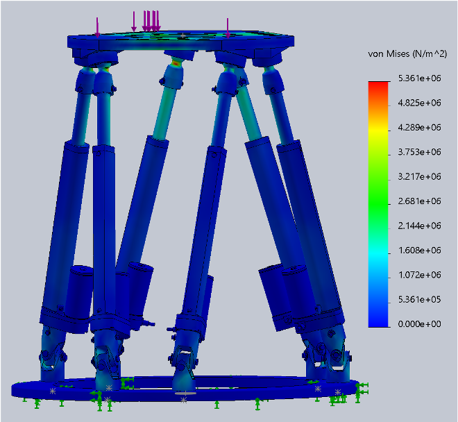
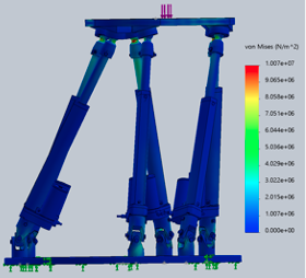
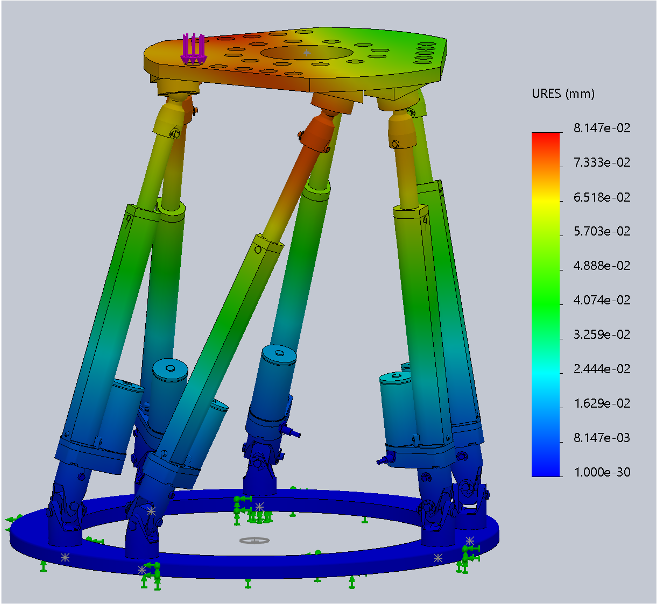
Our load capacity constraint is to ensure that the platform can withstand a weight of 100kg. We have tested our SolidWorks model using the finite element analysis tool. This test allowed us to determine the internal stresses developed in the mechanism. From this analysis, we confirmed the strength of our mechanism, as the maximum stresses shown were significantly below the material’s yield stress. This analysis ensures the strength of our Stewart Platform, as it is essential that our mechanism is lightweight but durable enough for frequent transportation and operation.
How we Validated our Design Solution
The design verification process consisted of testing the device through load simulations and motion studies. We performed over 30 different iterations on our model that consisted of manipulating and tweaking the material, size, load capacity, type of fasteners, and joint coatings. This allowed us to test our final design to prove that the mechanism operates as defined by the project sponsors requirements.
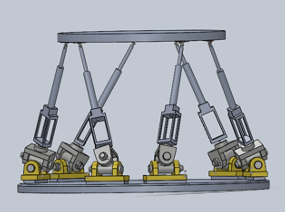

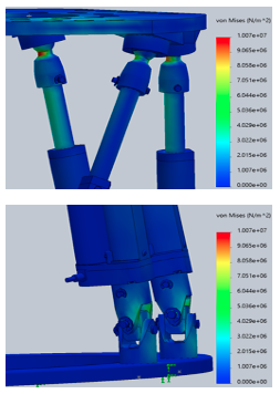
The load capacity was verified using the Static Study function in SolidWorks Simulation, we have simulated a working environment with complex forces and stresses to display the load capacity and stress deformation of our mechanism at its ‘home’ position and its maximum required workspace position.
Home Position Load Capacity Analysis
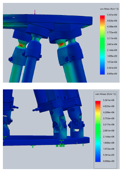

Maximum Workspace Load Capacity Analysis
The workspace of the mechanism was verified using Motion Studies in SolidWorks Motion to demonstrate the position and rotation requirements.
Planar Workspace Simulation
Vertical Workspace Simulation

Rotation Workspace Simulation
The weight requirement was satisfied through mass evaluations in SolidWorks for the chosen material of 6061 aluminum alloy with a final weight of 14.54 kg.
Partners and Mentors
We would like to thank project sponsors Binbin Lian, Ximming Huo, and Tao Sun, as well as students Shiruo Zhang, and Haonan Liang from Tianjin University in China for their continuous support and feedback that have helped us throughout this project.
We would also like to express our gratitude to both Dr. Qiao Sun and Dr. Peter Goldsmith from the University of Calgary for their invaluable guidance, engagement and remarks that have helped us throughout the learning process of this project.
Lastly, we’re grateful for Dr. Simon Li and Min-Hyung Lee’s constant advice and direction which allowed us to elevate our project further.
Our Photo Gallery

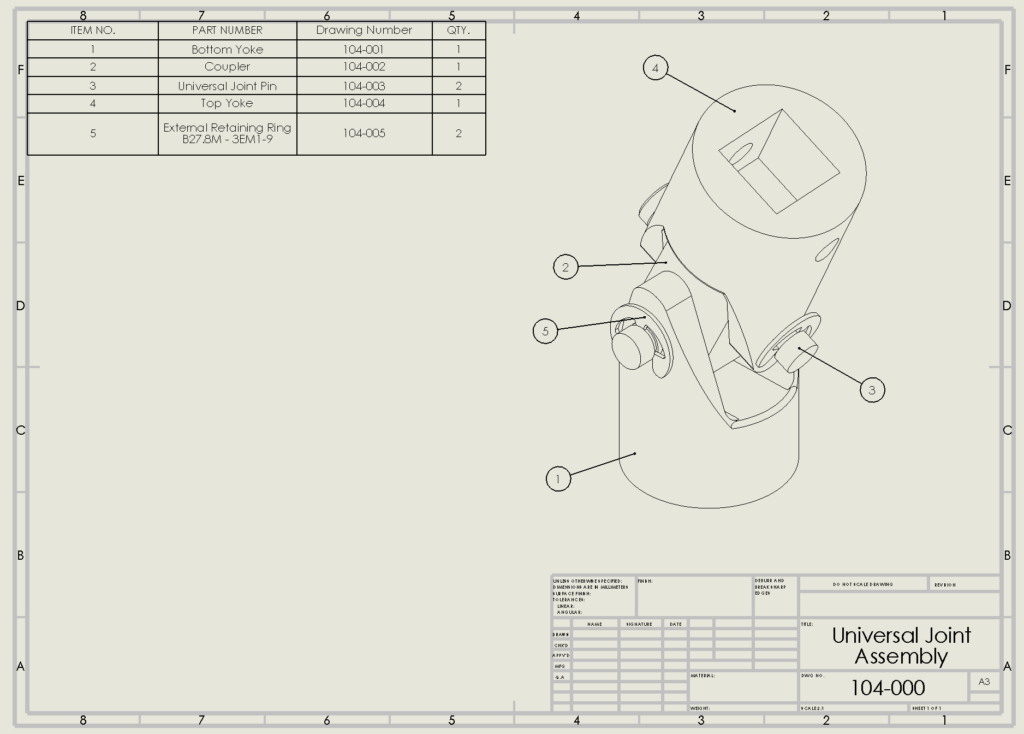
CAD Drawings