PROJECT CATEGORY: MECHANICAL

__________________________________________________________________________
Come Visit us on Zoom!
Date: Tuesday, April 5th, 2022
Time: 10:00 AM – 12:30 PM MDT
Meeting ID: 581 676 6001
Please email stephen.ciezki@ucalgary.ca if you have trouble joining and need assistance in joining the zoom meeting
ABOUT OUR PROJECT
The purpose of this capstone project is to design a feasible and reliable water storage facility for operation on the surface of the Moon. The water storage facility must be capable of storing 10,000 kg of water, and it must be able to function automatically. Furthermore, the water storage facility must be designed to survive the harsh Lunar conditions of its environment, the most important Lunar conditions that drove the engineering design considerations are stated below:
Lunar Conditions:
- Temperature ranges from 41 K (-232°C) to 400 K (127°C)
- There are 14 day long Lunar day and Lunar night cycles
- The atmosphere is a hard vacuum
- The gravity on the Moon is 1.62 m/s2
The main criteria considered for selecting our solution include safety and risk mitigation, operability, and cost.
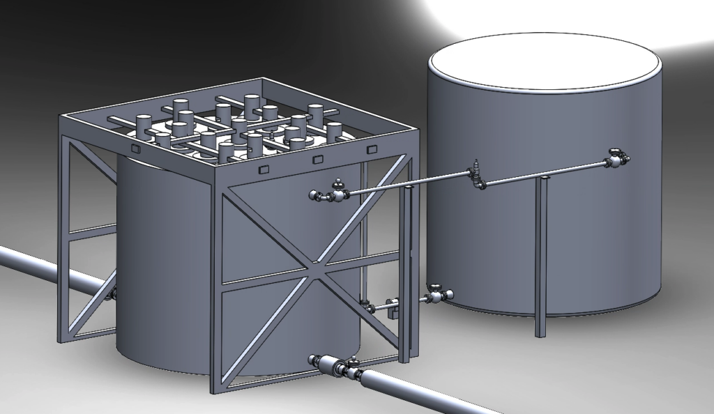
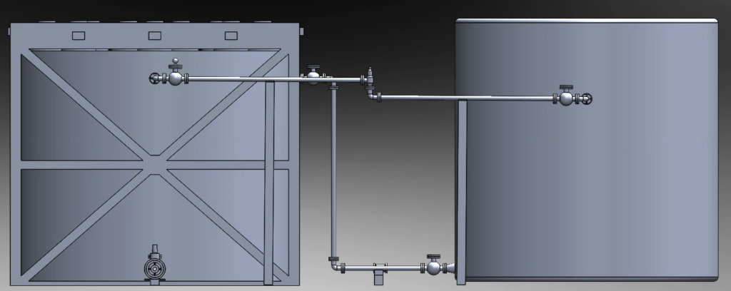
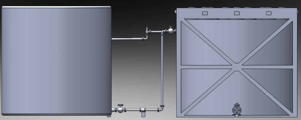
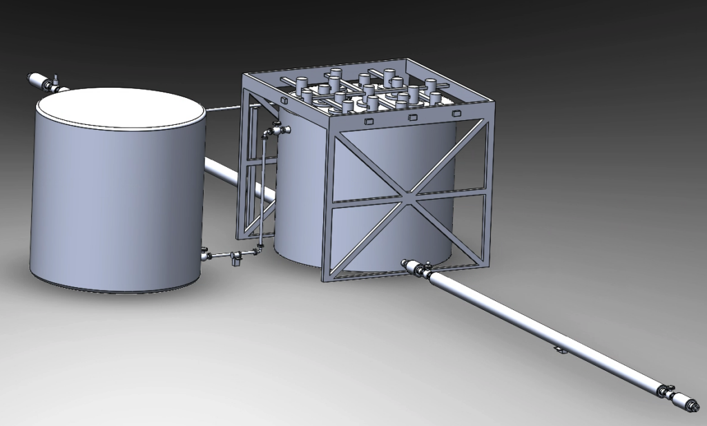
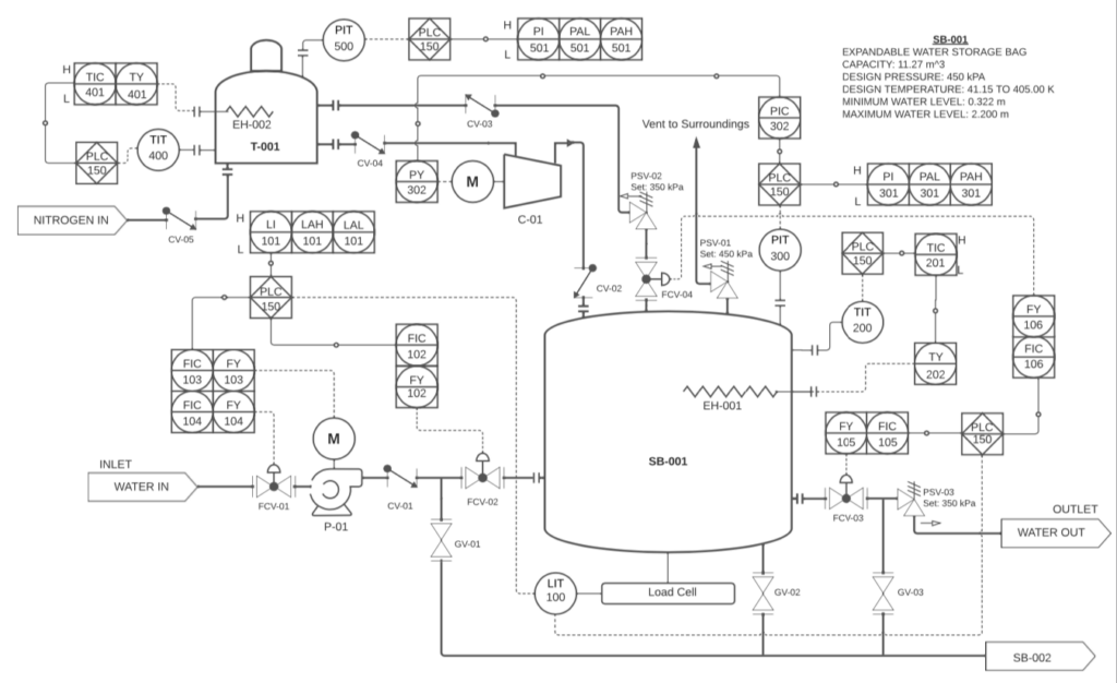
The selected design includes four main components: the inlet water transfer line, the water storage vessel, the outlet water transfer line, and the nitrogen blanketing gas system.
______________________________________________________________________
MOTIVATION OF THE DESIGN
Water is a critical resource in the aerospace industry as it has a vast assortment of applications ranging from its requirement for life support, to its use in rocket fuel through splitting H2O(l) into its principal elements of H2(g) and O2(g) through the process of electrolysis. Currently, it costs about $100,000 to transport one gallon of water to the Moon [1] putting an excessively large price tag on such a critical resource. As water is imperative to increase the robustness of human space exploration, there is a clear need for development in the space resource industry with an emphasis on developing infrastructure to greatly reduce this cost.
Furthermore, the space resource industry is in its very early stages, resulting in tremendous growth opportunities in this sector. Considering the space resource industry is in its infancy, there is an extremely limited supply of data on how industrial processes work in aerospace environments, including Lunar environments. With the lack of applicable data, and a limited understanding of how industrial processes may operate in Lunar conditions, there is fantastic opportunity for engineering-based developments and research to build a foundation in the development and implantation of space resource infrastructure. Researching and understanding how industrial processes may work in a Lunar environment is a critical step in driving advancements in the space resource industry and aerospace industry as a whole.
Based on the motivation of generating an understanding of how industrial processes can operate in a Lunar environment, and the need to significantly reduce the cost of utilizing the critical resource of water on the Moon, this capstone project aims to develop foundations for creating infrastructure on the Moon to transport and store water in a safe and economical manner in conjunction with Lunar Water Supply Company (LWSC).
DESIGN OVERVIEW
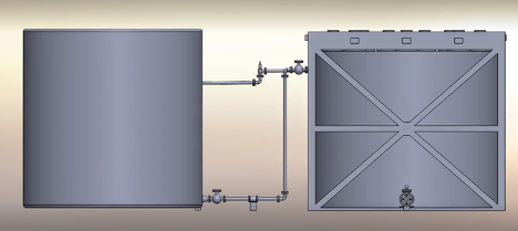
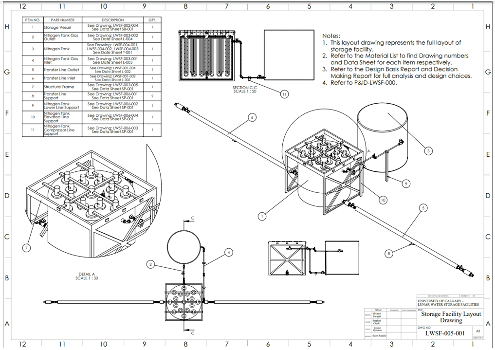
Final Concept
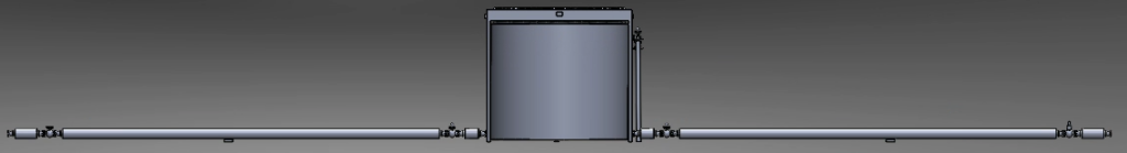
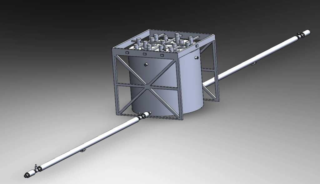
The water will interact with four main components and will be transported to the 8.2 m x 25.5 m facility. Water first enters the facility at the entrance of the inlet transfer line and is then transferred into the storage vessel via a transfer pump. Here water is stored (either as a liquid or solid), until it is required for delivery. At this point, water is exported as a liquid through the outlet transfer line and delivered to the customer.
Four Main Components
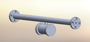
Inlet Water Transfer Line
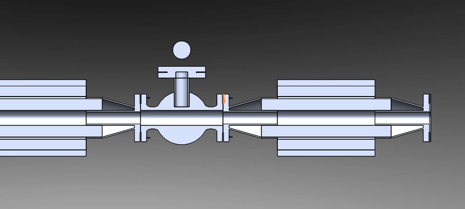
Utilizing the transfer hose design, the inlet of the transfer line receives water in liquid form and allows for the transportation to the storage vessel. Check valves and flow control valves are strategically placed to prevent unwanted conditions and process flows.
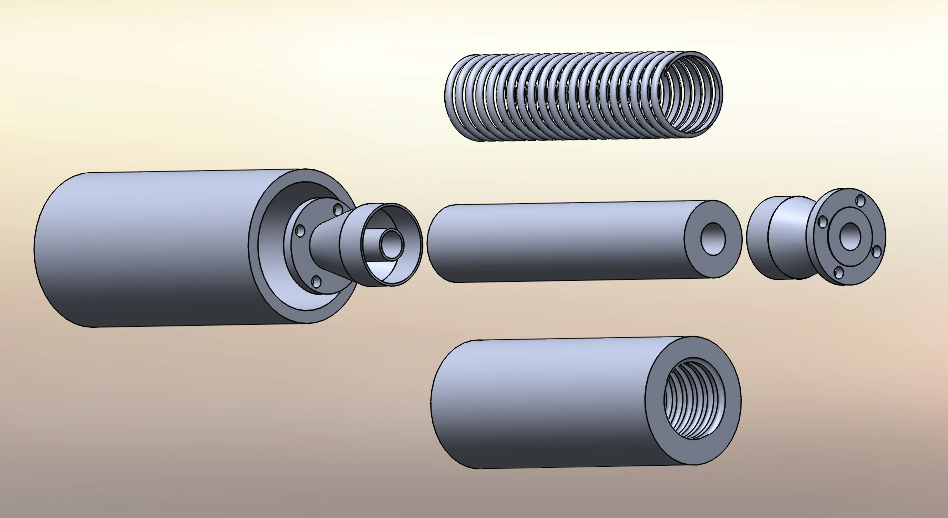
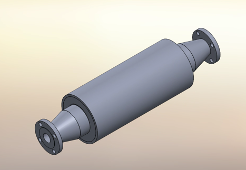
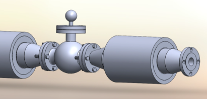
Due to the harsh pressure condition produced by vacuum, water can be evaporated immediately when exposed to the environment. The solution developed consists of having a heated and pressurized expandable hose material to maintain a certain pressure of 350 kPa. The hose consists of four main components: the expandable hose, coiled heating element, insulation, and an outer protective shell.
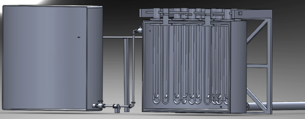
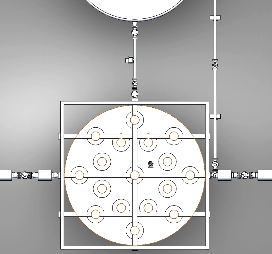
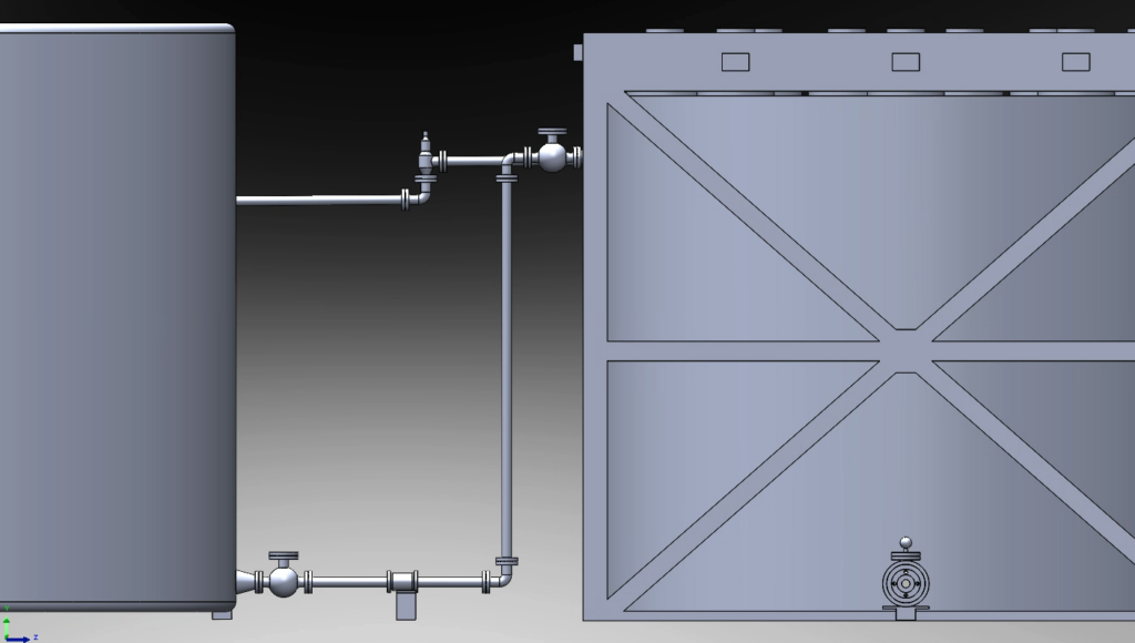
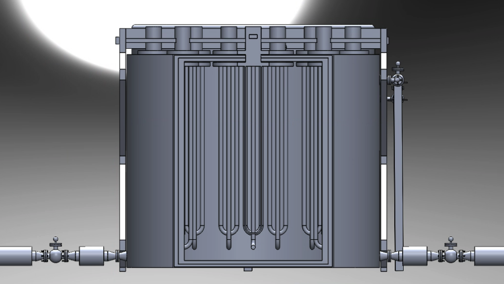
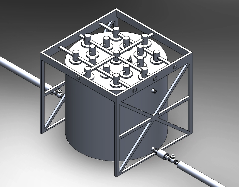
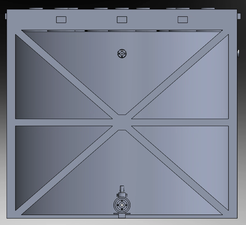
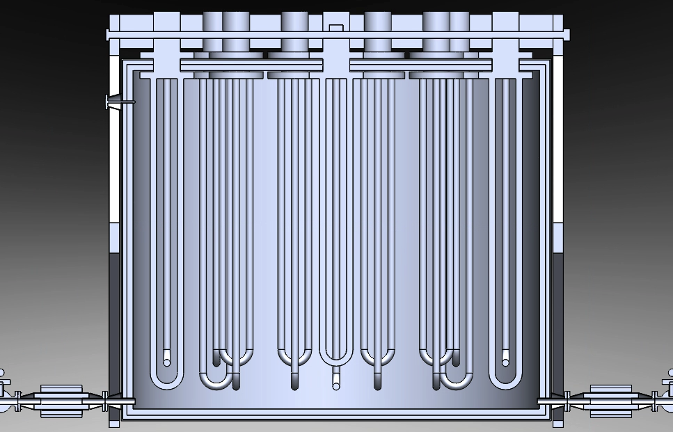
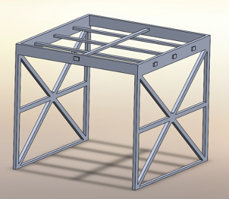
Storage Vessel
The storage vessel is designed to contain the transported water at either liquid or solid state. The vessel will always be maintained at 350 kPa to ensure that the water will never enter a gaseous state during any lunar condition. Resistance heaters are suspended above the bag and attached to the storage vessel structural frame to provide structural stability as seen in the animation below. These heaters attached to the storage vessel provide volatility for long- and short-term storage. The heaters are designed to apply the appropriate heat either in frozen conditions or to maintain water as a liquid for transportation.
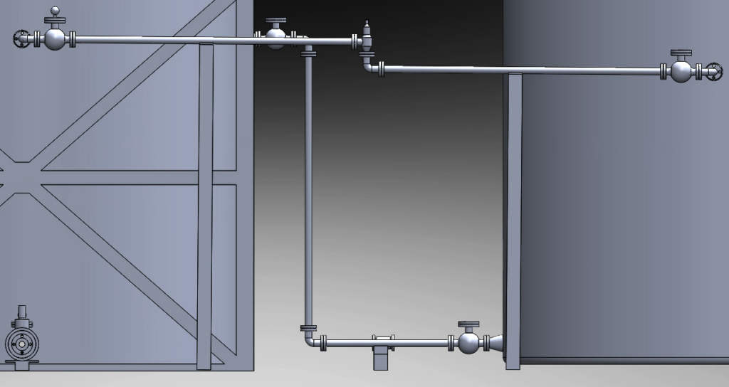
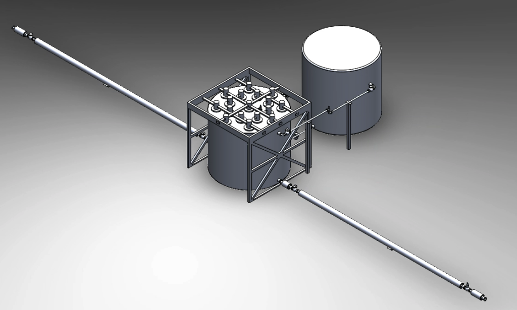
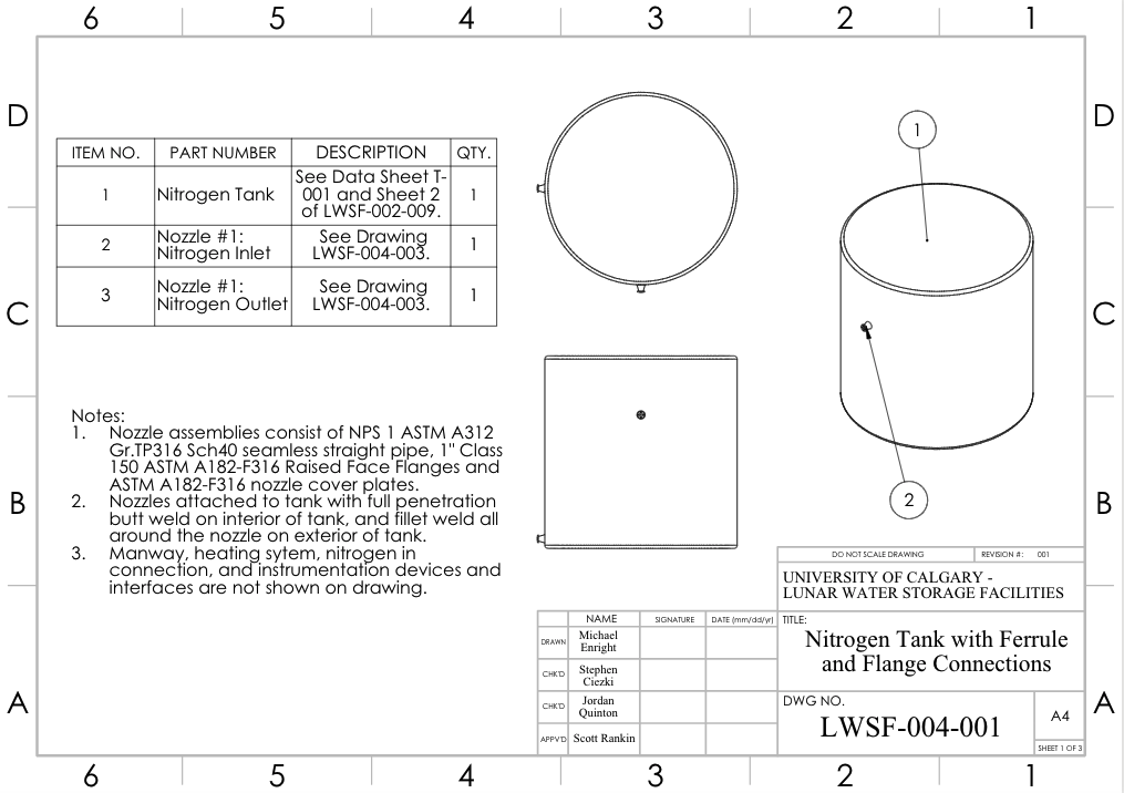
Nitrogen Blanketing Gas System
A separate tank will provide the necessary inert gas to produce an artificial atmosphere that will pressurize the storage vessel at 350 kPa. The inert blanket gas this design will use is nitrogen as it can be maintained as a gas at low temperatures and is immiscible with water. Via compressor, the nitrogen tank will be accommodated with the appropriate piping and valve system to ensure the water will never enter the nitrogen tank with the added benefit of transporting water through the outlet transfer line by changing the control valve positions. The storage vessel will maintain a minimum water level to prevent the blanketing gas from entering and choking the water transfer lines.
Outlet Water Transfer Line
Like the inlet transfer line, the outlet line serves the purpose of transferring water, but now it is being transferred out of the storage vessel and outputted for customers. Once the water has been outputted, the water storage facility process has completed one full cycle.
DETAILS ABOUT OUR DESIGN
HOW OUR DESIGN ADDRESSES PRACTICAL ISSUES
Water Evaporation Mitigation
One of the biggest concerns with the Lunar water storage facility is the possibility of water evaporating while inside a pressurized component, which could result in drastic bursts and leaks. If a burst were to occur, water would be lost from storage, and the facility would be severely damaged. To address this issue, a pressure control system was implemented into our design to regulate the pressure of the system and ensure water does not evaporate. An operating pressure of 350 kPa was selected because at this pressure, water does not evaporate until it reaches a temperature of 412 K (139°C). The highest temperature of the Moon is 400 K (127°C), so even if the water temperature is elevated to that of its Lunar surroundings, it will remain in its liquid phase, eliminating the risk of water evaporation. To achieve an operating pressure of 350 kPa for the entire storage facility, a nitrogen gas blanketing system was developed which works by filling the extra volumes in the storage vessel with nitrogen through the use of a compressor, pressure relief equipment, and pressure control instrumentation.

Heating Systems
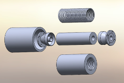
Considering that a Lunar night cycle can reach a temperature of 41 K (-232°C), it is clear that system components may be cooled to sub-freezing temperatures during a Lunar night. Water would shortly freeze if it was introduced into the system when water containing materials are at sub-freezing temperatures, which would restrict the storage facility’s ability to input and output water. To address this issue, the team developed two extremely efficient heating systems to regulate system temperatures. The first heating system is for the transfer lines, where a nichrome helical wire is wrapped around the water containing PTFE tube, and it works by providing resistance heating to the PTFE tube, when an electrical current is applied to the helical wire, which then transfers heat directly into the water.
The second heating system is for the water storage vessel where a set of immersion heating units are inserted via a flanged connection into the storage vessel to provide resistance heating directly to the water. Both heating systems utilize resistance heating methods, which are nearly 100% efficient [2], and are fully capable of maintaining water at operable temperatures, even in the extreme cold conditions of a Lunar night.

WHAT MAKES OUR DESIGN INNOVATIVE
Adaptive Material
The water transfer lines and the storage vessel are strategically designed with polymer materials that utilize mechanical properties that can elastically expand with the expansion of water as it freezes: this means that if a power failure were to occur, and heat cannot be provided to the system, the facility can safely adapt with the expansion of water as it freezes, and then later return to its original shape.
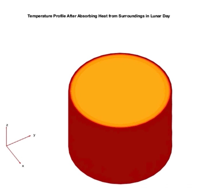
Utilization of Ambient Temperatures
The storage facility is designed to utilize the ambient temperature of the Moon during a Lunar day as a heat source for the water. During operation within a Lunar day, when the ambient Lunar temperature can reach 400 K (127°C), the heating systems of both the storage vessel and the transfer lines can be shut off, and the heat transferred from the Lunar surroundings into the water retains water in its liquid state, and at effective temperatures. This significantly reduces the amount of energy required for the internal heating systems, as the heating systems essentially only need to operate in Lunar nights.
Multifunctional Compressor
The compressor located in the nitrogen blanketing gas system has the dual purpose of regulating the internal pressure of the system and exporting water through the outlet line. The instrumentation control loops were strategically designed to allow the compressor the ability to also output water from the storage vessel through the outlet transfer line as required. By designing instrumentation systems that allow for this dual functionality of the compressor, a second transfer pump is not required for the outlet line, minimizing the total mass of the water storage facility.
WHAT MAKES OUR DESIGN SOLUTION EFFECTIVE
Adaptable Storage Methods
The storage vessel is designed for operation in two water storage modes, short-term storage as a liquid, and long-term storage with liquid and solid cycles. As our storage vessel is designed with a flexible polycarbonate shell that can accommodate any volume changes between liquid water and ice, water can be effectively stored in either phase. For short term storage, when water must be readily available for export at any time, the water will be stored as a liquid. However, to reduce energy consumption for long-term storage, the storage vessel heating system can be powered off, and now during storage water will exist as a liquid throughout the Lunar Day cycle, and freeze into ice during the Lunar Night cycle, saving a total of 6.48 x 10⁹ J of energy for every Lunar night cycle.
Throughput Capabilities
The Lunar water storage facility has a very effective throughput, where the maximum amount of stored water (11,274 kg) can be completely outputted from the storage vessel in a period of 8 hours, and then the maximum amount of water can be inputted back into the storage vessel in a period of 8 hours. This gives a total time of 16 hours to completely empty the storage vessel and fill it up again. If water needs to be exported while the system is utilizing long-term storage methods and the stored water is currently frozen, it takes the heating system 8 hours to completely melt all 11,274 kg of ice. In this case, there is a total time of 24 hours to completely empty the storage vessel and fill it up again.
HOW WE VALIDATED OUR DESIGN SOLUTION
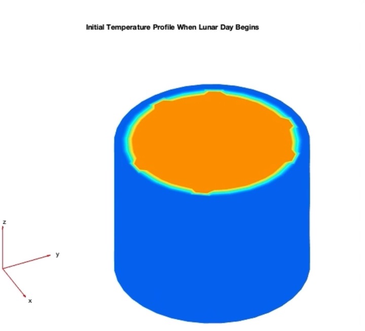
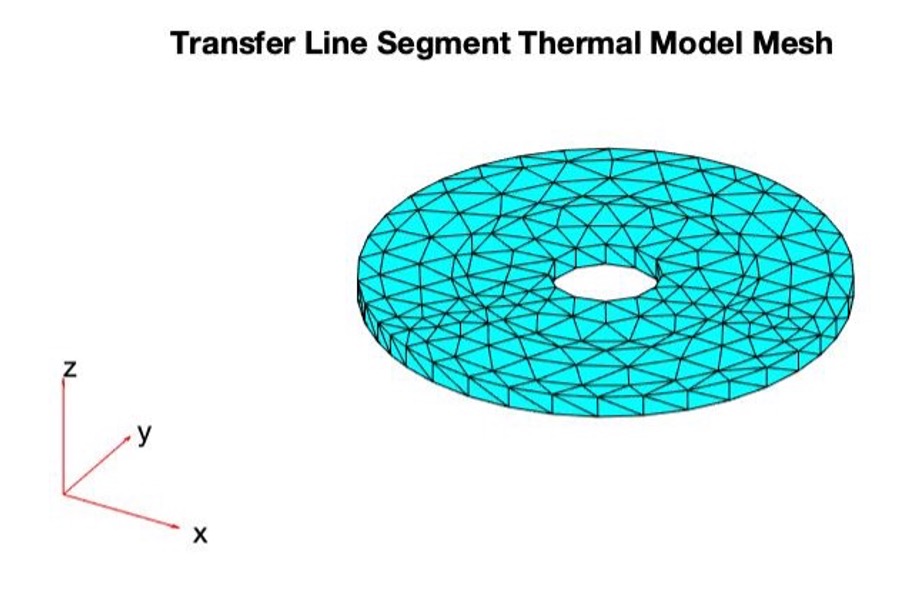
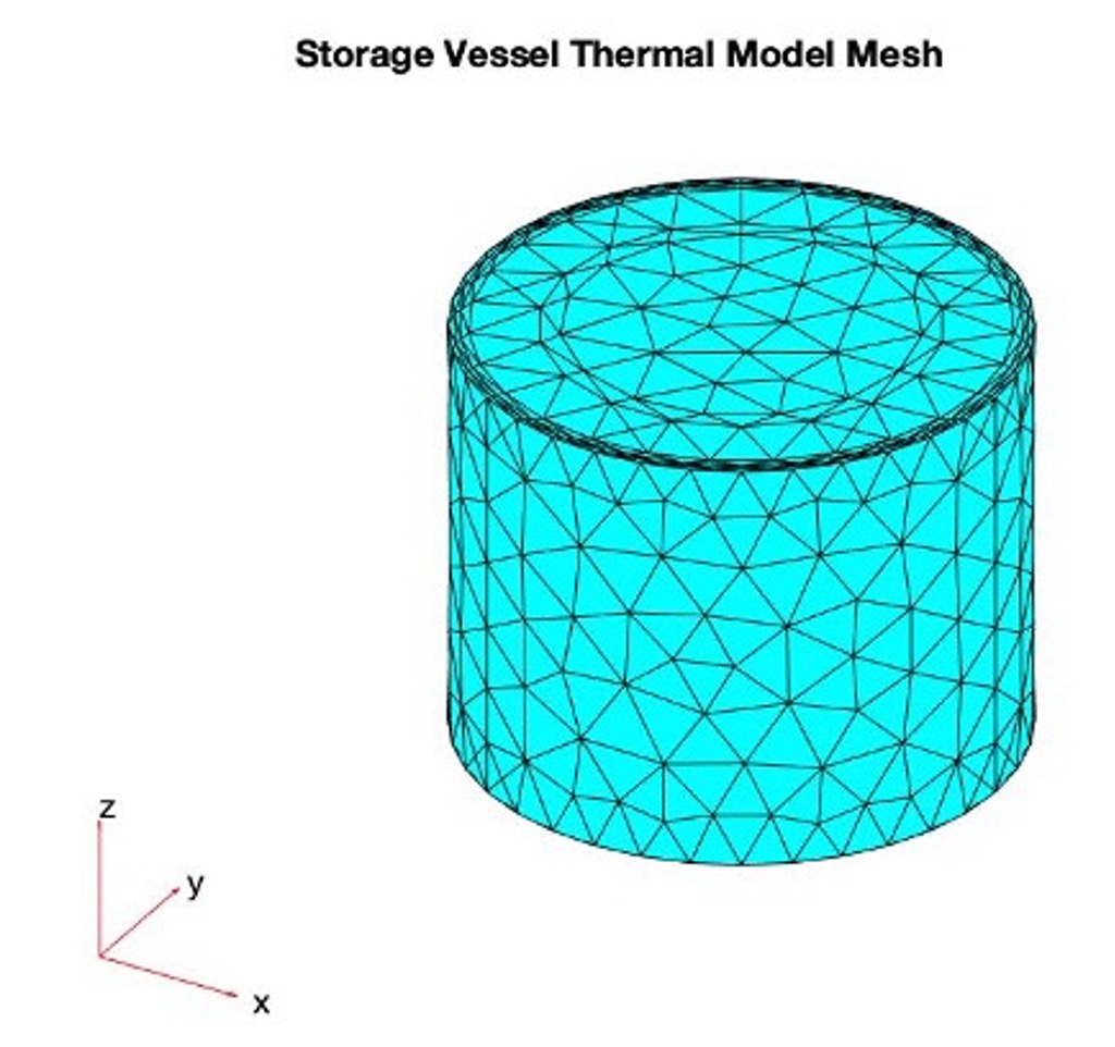
Thermal Model Simulations
To ensure all materials in the storage facility stay within their temperature limitations, and to verify water is kept at its operating temperature, the team developed a thermal simulation program on MATLAB to continuously simulate the temperature profiles of the transfer lines and storage vessel for any specified time range. The thermal simulation program works by creating mesh objects of the transfer lines and storage vessel with precisely defined geometry, material properties, and boundary conditions, the thermal simulation program then computes finite element analysis calculations on thousands of cells that compose the mesh objects to calculate the heat transfer effects as a function of time. Finally, the simulation outputs temperature gradients of the storage facility so the temperature of the storage vessel and transfer lines can be viewed for a set time range. The thermal simulation program was used to test the temperature profiles of a series of different initial conditions on the system which would be seen during operation. Using this program, the team was successfully able to verify that all the materials in the storage vessel and transfer lines experience temperatures within their maximum temperature limitations. The thermal simulation program was also used to successfully verify that water remains close to its operating temperature and in its liquid phase throughout the entire process.
Industry-Based 3 Stage Approval Approach
Every drawing and data sheet produced for this capstone project requires a three-stage approval in which three signatures from three separate team members are necessary for a drawing or data sheet to be deemed complete. Once a drawing or data sheet has been created, the designer of the document will check through all the dimensions, notes, numbering, and design, and provide their signature indicating they have thoroughly reviewed the documenting. Then the document is sent to the “checker” who will complete a detailed evaluation and either propose revisions for the drawing/data sheet or provide their signature indicating their approval. After two signatures are present, then the document moves on to the “approver” who will complete their analysis and review of the drawing/data sheet, and again either propose revisions, or approve the document by signing it. This 3-stage approval method is commonly used in the engineering industry to verify engineering design at the pre-construction stage and was adopted as an approval requirement for our capstone project to verify all the drawings and data sheets in our design.
FEASIBILITY OF OUR DESIGN SOLUTION
Low Overall Material Mass
The materials have been strategically chosen to minimize the overall mass of the storage facility and reduce transportation costs while maintaining the structural integrity of the facility. Additionally, all materials used in this design are prevalent in industrial processes on Earth and will be easily attainable for a project of this scope and size.
Easy Constructability
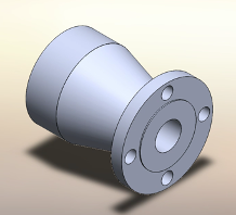
The design features a duplication of critical components and parts to create redundancy across the entire storage facility, this redundancy makes the design more easily scalable and reduces the amount of new, unique components required in construction. Also, the main interface used to connect various components across the storage facility is flanged connections which utilize bolts and studs. This greatly reduces the complexity of the assembly process, as parts and components can be easily bolted together.
Automated Process
The storage facility has been automated through the design of our instrumentation control system to eliminate the need for human labour associated with the water storage and transportation process. This minimizes the potential for human error, reduces operational risks for humans, and makes operating the complex system very simple and efficient.
OUR PROJECT POSTER
MEET OUR TEAM

brandon.gonzalez@ucalgary.ca

desmond.seto1@ucalgary.ca

jordan.quinton1@ucalgary.ca

Michael.enright@ucalgary.ca

stephen.ciezki@ucalgary.ca

wael.alharrasi@ucalgary.ca
PARTNERS AND MENTORS
We would like to extend a huge thank you to everyone who provided feedback and support with our design, especially our industry sponsor Lunar Water Supply Company, and the University of Calgary faculty.

Zac Trolley, P.Eng.
Sponsor
Co-Founder & CEO
Lunar Water Supply Company
________________________________________
Scott Rankin, P.Eng.
Sponsor
Lead Process Engineer
Lunar Water Supply Company
__________________________________________

Danny Wong
Teaching Assistant
Doctoral Student
University of Calgary
____________________________________________
Seonghwan (Sam) Kim
Academic Advisor
Associate Professor
University of Calgary
_____________________________________________
Dr. Philip Egberts
Course Instructor
Associate Professor
University of Calgary
______________________________________________
OUR PHOTO GALLERY
CAD Drawings & Data Sheets
CAD Models