Project Category: Mechanical
About our Project
Convective heat transfer in microchannels is a promising high-efficiency cooling strategy and can be used for many types of high-power devices, such as microprocessors and laser optics. Boiling heat transfer in microchannels can not only utilize the latent heat of the working fluid to enhance the heat transfer capacity, but is also benefit from the recirculating flow induced by fluid interfaces. Certain parameters influence microchannel performance such as fluid properties, bubble dynamics, and bubble trains [1].
High-efficiency cooling is important in numerous applications, such as in microprocessors with very-large-scale integration and in commercial/military high-power optical/electronic systems. The heat generated by such devices must be removed rapidly to ensure the reliability of the devices. Comparing with other cooling techniques, microchannels can be directly embedded closely to heat sources for compact and efficient designs [1].
In this collaboration project with Tianjin University (TJU) in China, the boiling heat transfer in microchannels will be studied by numerical simulation. Numerical simulations can serve as an important way to study convective heat transfer in microchannels without building complex diagnostic systems [1].

For a high-level look into our project and our design solution, please watch the video linked below or join us in the zoom link for a Q&A and deeper dive into our design solution.
Meet our Team Members
Due to our small team, both team members were in involved with all aspects of the design including development, verification, project management, communications, and more.
Brady Kueneman
Brady is currently finishing his mechanical engineering degree, combined with a 16 month internship working at an oil and gas company.
Brady enjoys his spare time creating the perfect French press coffee.


Connor Lowe-Wylde
Connor is currently finishing his mechanical engineering degree and completed a 16 month internship, working in the hydraulics engineering group at a midstream oil and gas company.
Connor enjoys his spare time fly fishing at his home town in the Crowsnest Pass, Alberta.
Design Fair Poster
Details about our Design
DESIGN OVERVIEW
Our design was created by producing a model in OpenFOAM (open source CFD software). This software allowed us to manipulate the flow conditions, fluid properties, and bubble dynamics (including bubble trains) to optimize our microchannel to come up with our design. The specifications for our microchannel are described and shown below.
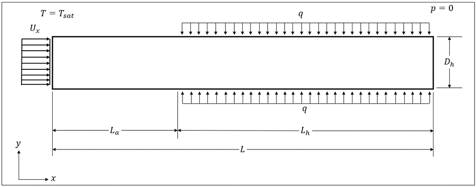
Our microchannel has a length of 30mm and has a square cross section with a side length of 1mm. There are two regions, an adiabatic region (length of 10mm) and a heated region (length of 20mm) with a constant surface heat flux of 90,000 W/m2. The temperature is forced at the inlet of the microchannel to the saturation temperature of r134a . The inlet velocity was specified as a uniform velocity profile of 0.26 m/s. The pressure at the outlet is set to a reference value of 0 Pa.
The initial research proved that a microchannel of this size should be able to produce a heat transfer rate of roughly 10 kW/m2 and maintain wall temperatures of around 70 degrees Celsius [2]. To establish these design parameters, we needed to study various fluids in the microchannel and bubble dynamics (coalescence).
After studying various fluids, r134a was chosen as the working fluid. In addition, it was found through optimization that the coalescence of multiple bubbles upstream of the heated region was beneficial to the overall heat transfer of the microchannel.
With the microchannel specifications, r134a, and coalescence happening upstream of the heat transfer region, our microchannel can cool the walls down to roughly 78 degrees Celsius with a peak heat transfer rate of approximately 30 kW/m2, which meets our design parameters. Below is a video of our two-phase boiling microchannel design simulation.
HOW OUR DESIGN ADDRESSES PRACTICAL ISSUES
Microprocessors generate significant amounts of heat. These processors can be found in commercial systems, military high power optical systems, electronic systems, and high performance computing systems. In order for these processors to operate, a heat exchanger must be designed that is able to cool the electronics and absorb enough heat. At the same time, these processors are very small, much means the heat exchanger must be small.
With our design specifications mentioned in the Design Overview section, we are able to meet these practical issues mentioned above. This is evident by meeting the wall temperature and overall heat transfer rate design parameters.
WHAT MAKES OUR DESIGN INNOVATIVE
Our design is based on the foundation of three dimensional, two-phase flow fluid dynamics simulations that analyze both the overall heat transfer of the microchannel and the bubble dynamics of the gaseous phase. There isn’t much understanding and research in this field and the experiments of small microchannels are challenging and limited. Therefore, our design utilizing three dimensional computational fluid dynamics, the study of bubble dynamics, and the effect of coalescence makes our design innovative.
WHAT MAKES OUR DESIGN SOLUTION EFFECTIVE
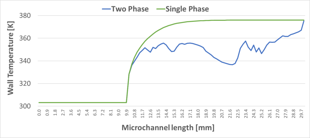
Our design is able to cool the walls in a more efficient manner then compared to a single phase boiling microchannel of the same size and conditions. The average heated wall temperature in our microchannel is 78 degrees Celsius, roughly 20 degrees lower then the single phase counterpart. Figure 4 shows this clearly.
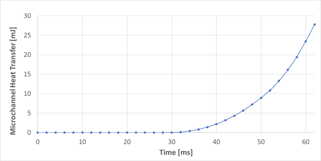
Our design also provides enough peak power to effectively cool the microchannel. Figure 5 shows the total heat transfer into the heated region. If we find the slope of this curve (rate of heat transfer), we can find the peak power of our microchannel, which is approximately 30 kW/m2. This meets our design parameter of removing 10 kW/m2, which makes our design effective.
HOW WE VALIDATED OUR DESIGN SOLUTION
To validate our OpenFOAM model, we ran a simulation with a single vapor bubble that studied bubble volume, bubble position, and the Nusselt number at a specific point in the microchannel. We compared our results with TJU’s previous study [3] that studied a model with the same flow conditions. The results showed an accurate comparison and further validated our model.
Partners and Mentors
We would like to thank the University of Calgary and TJU for collaborating on this project and allowing us to participate. We would like to express appreciation and gratitude towards TJU team members Dr. Zhizhao Che (Project Sponsor), Odumuyiwa Odumosu, and Xu Huashi. They have supported us in this project and spent time guiding us in the right direction. Additionally, we would like to thank Dr. Mohamed (Faculty Supervisor) from the UofC, who has provided us mentorship and guidance along the way. Dr. Mohamed provided a road map for us to better understand the problem at hand and the processes in which we should take to solve the problem.
References
[1] Z. Che, Project Proposal Form, Tianjin University (China), 2021.
[2] R. Mishra, “electronics Cooling,” 2004. [Online]. Available: https://www.electronics-cooling.com/2004/02/the-temperature-ratings-of-electronic-parts/. [Accessed 08 12 2021].
[3] O. A. Odumosu, T. W. Huashi Xu and Z. Che, “Numerical Investigation of Bubble Growth during Flow Boiling in Wavy Microchannels,” Tianjin University, Tianjin, China, 2021.
