Project Category: Mechanical
Check out our project in person!
Date: April 5th, 2022
Time: 10:00 a.m. to 12:30 p.m.
Location: Atrium CNRL Complex at the Schulich School of Engineering (Booth 7)
About our project
As the worlds daily energy consumption continues to increase, and the impact of climate change begin to become more apparent, the need for renewable energy is become heightened in the last few years. Our project proposes an environmental friendly, passive, and alternative way to harvest energy from a fluid flow using a phenomenon known as Flow-induced vibrations.
Flow-induced vibrations (FIV) are caused by boundary layer separation on a bluff body (e.g., a cylinder) submerged in a moving fluid [1]. The boundary layer separation on these bodies causes a vortex to form; when the vortex does not form symmetrically around the body, lift forces develop on each side of the body, leading to vibrations or an oscillatory motion perpendicular to the flow.
The energy associated with the oscillating motion of the cylinder can be harvested and used as electrical power. This energy harvesting phenomenon has the potential to be scaled up and widely used in several applications where flow passes by a cylinder, such as off-shore oil drilling, heat exchangers, chimneys, suspension bridges, and aero-elasticity. This method of renewable energy harvesting has been proposed as an alternative to areas where conventional energy harvesting is not economical or has a high environmental impact such as dams or water turbines.
The goal of our project is to build upon previous research [1][3] showing that placing a stationary secondary cylinder upstream of a primary, energy harvesting cylinder creates larger oscillations, and therefore more energy can be harvested. Our project focuses on moving the secondary cylinder with an optimal motion to harvest as much energy as possible.
We invite you to join us in person at the capstone fair to learn more about our project and to see a live demonstration of the actuator system!
Meet our team members

Phillip Milner
Phillip is currently in his final year of his mechanical engineering degree with a minor in mechatronics. During the project, he was able to make use of his previous work experience in manufacturing and prototyping to help design and fabricate the actuator system. With his hands on experience with mechatronic systems, he helped develop the electrical control of the actuator as well as the firmware. When he is not at school, or training for his next race, Phillip enjoys designing home automation systems which he shares on his website https://www.milnerautomations.com. He can also often be found in the mountains, climbing, backcountry skiing or trail running.

Matthew Mueller
Matthew is a final year mechanical engineering student pursuing a minor in mechatronics. His interests lie in renewable energy, robotics, data analytics, and computer programming. Matthew’s primary role in the project focused on the research, design, and fabrication of the actuator system, including its control circuit, firmware, and software interface. Some of his hobbies include skiing, golfing, CNC routing, and 3D printing.

Blair Jensen
Blair is currently in his final year of his mechanical engineering degree with a minor in mechatronics. His interests lie in robotics, dynamics & control, and in mechanical design. Blair’s primary role in the project was the design and construction of the sensor system, which included selecting sensors, manufacturing custom made amplifiers using PCB boards, constructing the sensors housing, and analyzing the pressure readings data from the sensors. In his free time, Blair enjoys coaching and playing hockey, golfing, fishing, and camping.

Matthew Lee
Matt is a mechanical engineering student with an interest in the energy industry and alternative energy technologies. Matt’s role includes the research, development, design, and construction of the sensor system. His hobbies include hockey, spikeball, basketball, jellyfish apparel, and eating.

Jonathan Brent
Jonathan is a mechanical engineering student with an interest in data science and machine learning and their applications to engineering problems. His primary role included the research and development of the neural network and predictive control system. His hobbies include mountain biking, skiing, hiking, motorcycles, and disc golf.

Sergio Anez
Sergio is a mechanical engineering student with interests in data analytics, sustainability, automation, and aviation. Sergio’s role included developing the machine learning Python code and the integration of the control system for the project. Some of his hobbies include playing basketball, football, travelling, and napping.
Details about our design
HOW OUR DESIGN ADDRESSES PRACTICAL ISSUES
As society transitions away from fossil fuels, the need for renewable energy has heightened. Presently, the most common sources of renewable energy are limited to hydro, wind, solar, and geothermal energy. While these sources provide a sustainable source of power for the world, they alone do not fully tap the all-natural renewable sources of energy. As rivers make up a large part of the earth, being able to harness their vast energy without impeding their flow would prove advantageous from an ecological standpoint.
Our capstone design strives to attain this objective by implementing energy harvesters that would more passively harness energy from water flow without the need for damming or diversion through turbines.
Provided a successful proof of concept, our project could be scaled to an industrial level which would position vertical cylinders in a river or canal flow and harness electricity through oscillation instead of rotation.
WHAT MAKES OUR DESIGN INNOVATIVE
Our project builds upon previous research [1][3] that has shown that placing a secondary cylinder upstream of a primary cylinder creates greater vortices, especially in larger flows, and therefore more energy can be harvested. Our project focuses on moving the secondary cylinder in an optimal motion to maximize the potential energy of the primary cylinder’s oscillations.
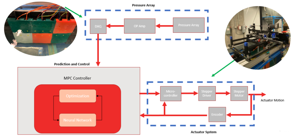
This is achieved by using sensors to measure the pressure in the water, a machine learning algorithm that uses the pressure data to calculate the forces on the primary cylinder, and an actuator system with closed-loop control that, in real time, positions the secondary cylinder in such a way that the oscillations on the primary cylinder are maximized.
WHAT MAKES OUR DESIGN SOLUTION EFFECTIVE
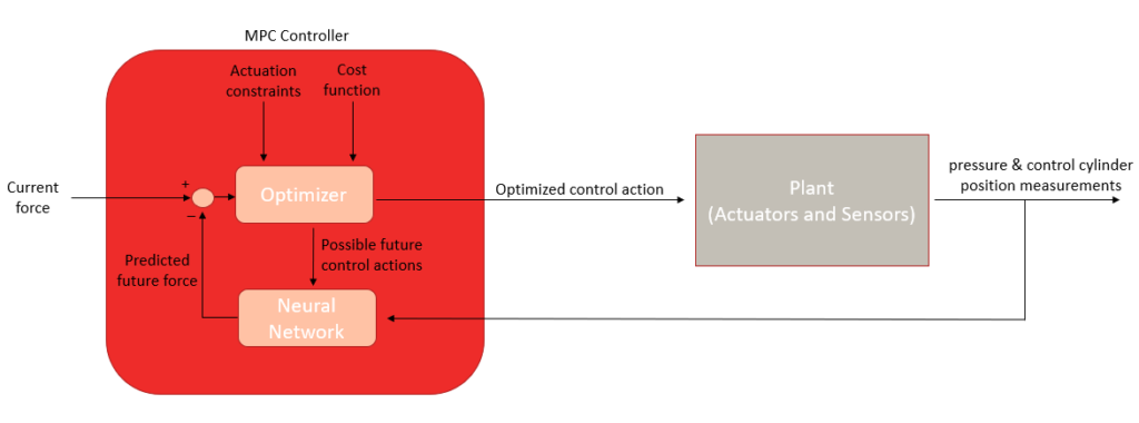
Our design solution is effective in that unlike previous implementations, our system uses real-time secondary cylinder movement. This feature is achieved by using a neural network and model predictive control strategy. Having this software interface allows us to predict future positions based on pressure data that is collected in real-time. Effectively, we can design our system such that the secondary cylinder is always in proximity to the primary to optimize vibrations. Optimizing the vibrations on the primary cylinder is crucial as it will allow the Flow Induced Vibration Energy Harvesters to have the greatest output power.
The method of control chosen for our project is Model Predictive Control (MPC). MPC is a control strategy that uses an internal model to make predictions of the systems behavior over a predefined prediction horizon. At each control step, the MPC works by:
- Measuring the current state of the system.
- Finding the actions that give the best predicted future performance according to the objective function.
MPC was selected because unlike traditional PID, it has predicative ability, meaning it can anticipate future events and take control actions accordingly.
HOW WE VALIDATED OUR DESIGN SOLUTION
Due to the complexity of the project, two levels of validation were implemented. The first was at the component level while the second validated the entire system. This was important since each of the project components had known specific requirements which needed to be met to successfully implement the system.
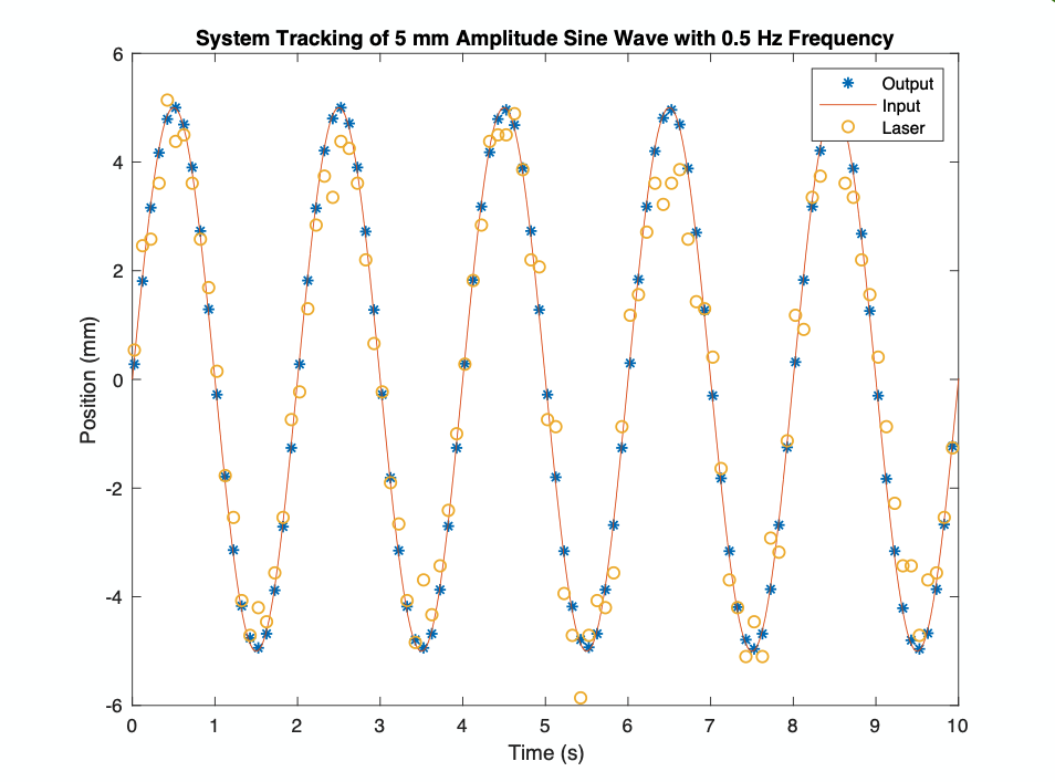
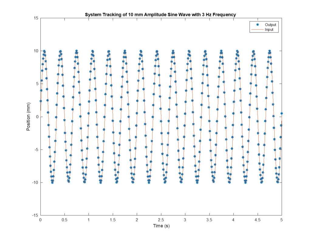
Initial fit and assembly of the actuator system was validated using SOLIDWORKS. The system was modelled and installed within a virtual model of the water channel to ensure proper fit. The motors and encoders were tested and validated with the use of an analog laser. System tracking was confirmed for a range of inputs to ensure it would be able to track the input from the predictive control.
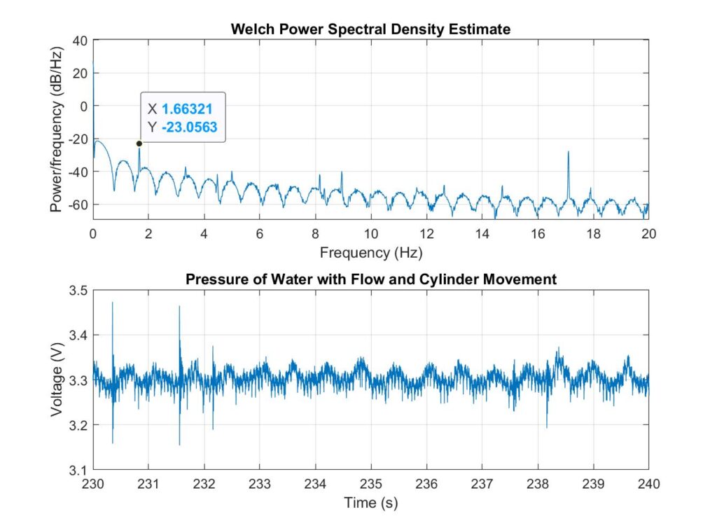
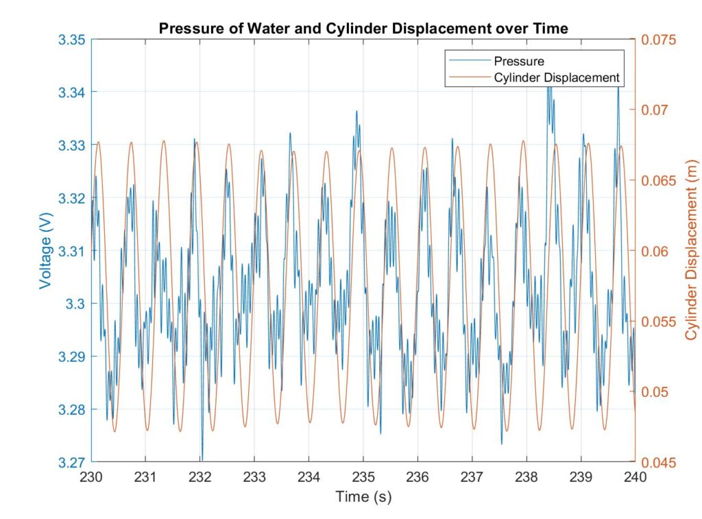
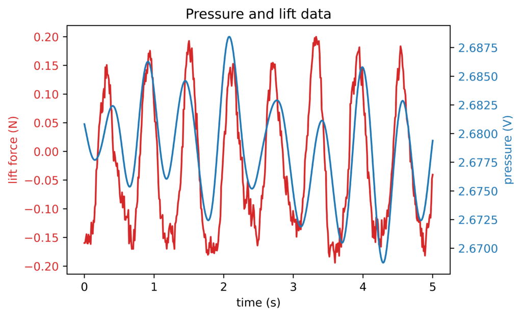
Sensor validation was done by comparing pressure readings in the water channel with the displacement of the oscillating cylinder. It was seen that both measurements followed similar sinusoidal curves, which were aligned and in-phase, thus the sensor system was able to correlate pressure at the walls of the channel to the movement of cylinder. Additionally, a power spectral density plot was generated, and it was seen that a frequency of 1.66Hz was evident in our system, as expected.
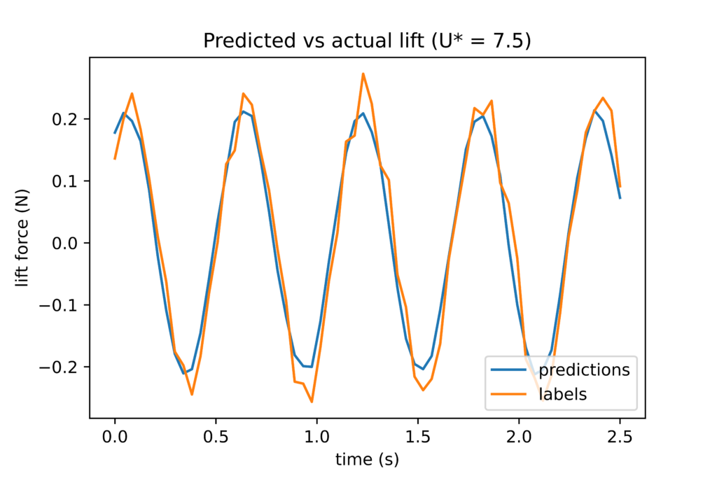
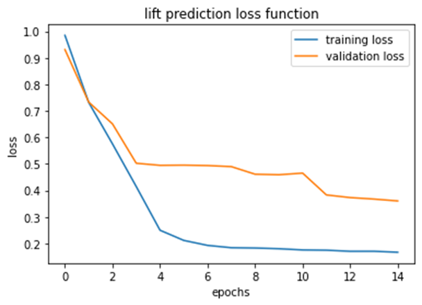
The neural network was built using a Long Short-Term Memory (LSTM) architecture. An LSTM was chosen due to its feedback connections which allow it to process sequences of data. This was especially useful for making future predictions on the state of the cylinder given our time series pressure data. The first prototype of an LSTM was built using an input of time history velocity data in the flow, with the output being the lift force on the cylinder 2.5 seconds in the future. The model’s predictions were then compared to data from a force transducer on the cylinder.
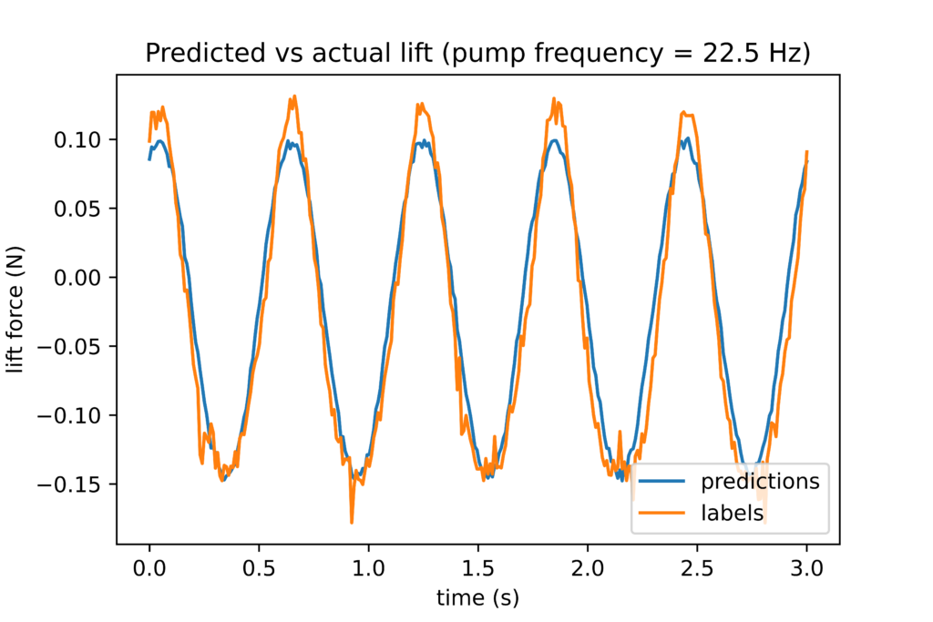
Once the pressure sensors were able to gather data on the water channel, another LSTM prototype was built that predicted lift force on the cylinder 0.1 seconds into the future using the data from the pressure sensors. We then compared the model’s predictions to the actual lift force on the cylinder, resulting in a root mean squared error of 0.033 N.
Final Design Testing
Once each sub system had been built, various tests were run on a small-scale water channel with all the sub systems now merged. To train the neural network, the pressure and the cylinder lift force data was collected while the actuator system was moved across the channel and back with step sizes of 1 cm occurring at intervals of 30 seconds.
Testing between a stationary and oscillating secondary cylinder proved to have noteworthy results on the primary cylinder, proving our design validity. An oscillating secondary cylinder created larger lift forces on the primary cylinder, up to a 25% difference in amplitude. Our hope is that when this technology is scaled up, we can see similar percent differences and create more energy that can be harvested.

We are currently in the process of building the control system. We have come across some challenges such as malfunctioning equipment and water channel scheduling that have delayed our testing. We are currently gathering data encompassing the entire actuation space and training the neural network with our new model architecture.
FEASIBILITY OF OUR DESIGN SOLUTION
Our design is simply a proof of concept, showing that a closed loop secondary cylinder will increase the amplitude of oscillation on the primary cylinder, thus, in theory, more energy can be extracted. Our design solution will help future research into this technology, as this technology is still very new. Our hope is that our design solution is a catalyst to mature flow induced vibration technology.
DESIGN OVERVIEW
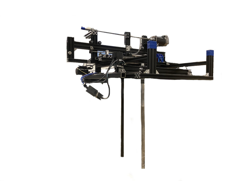
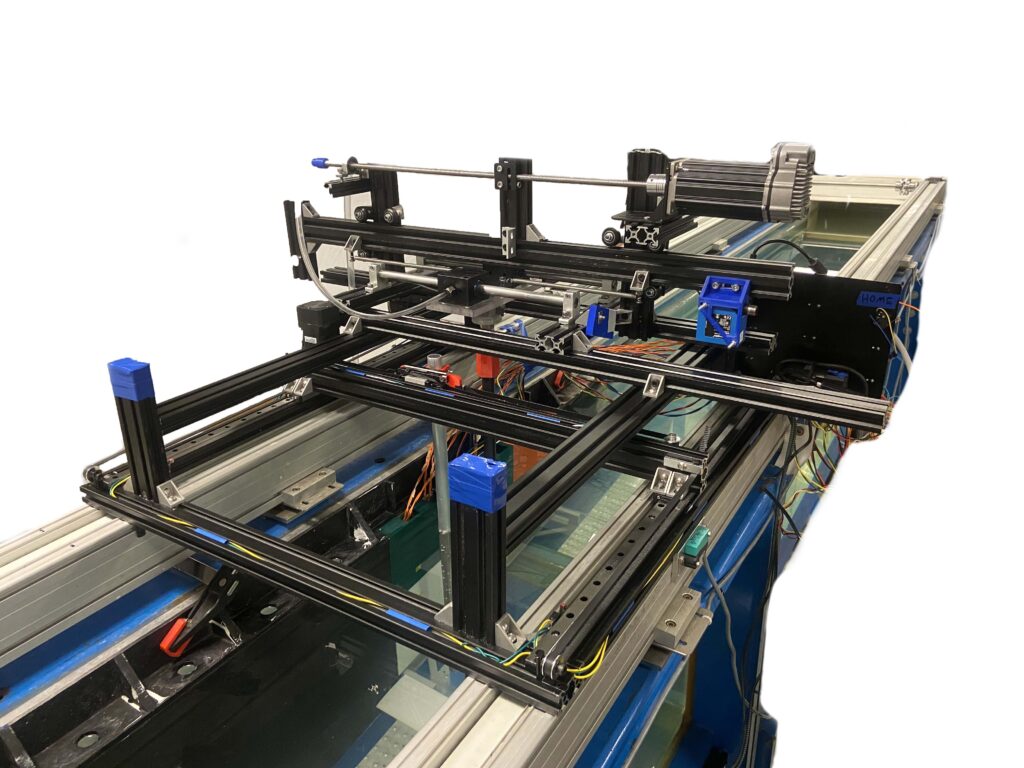
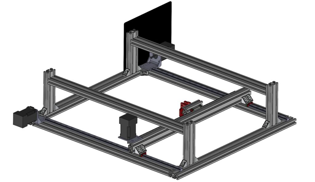
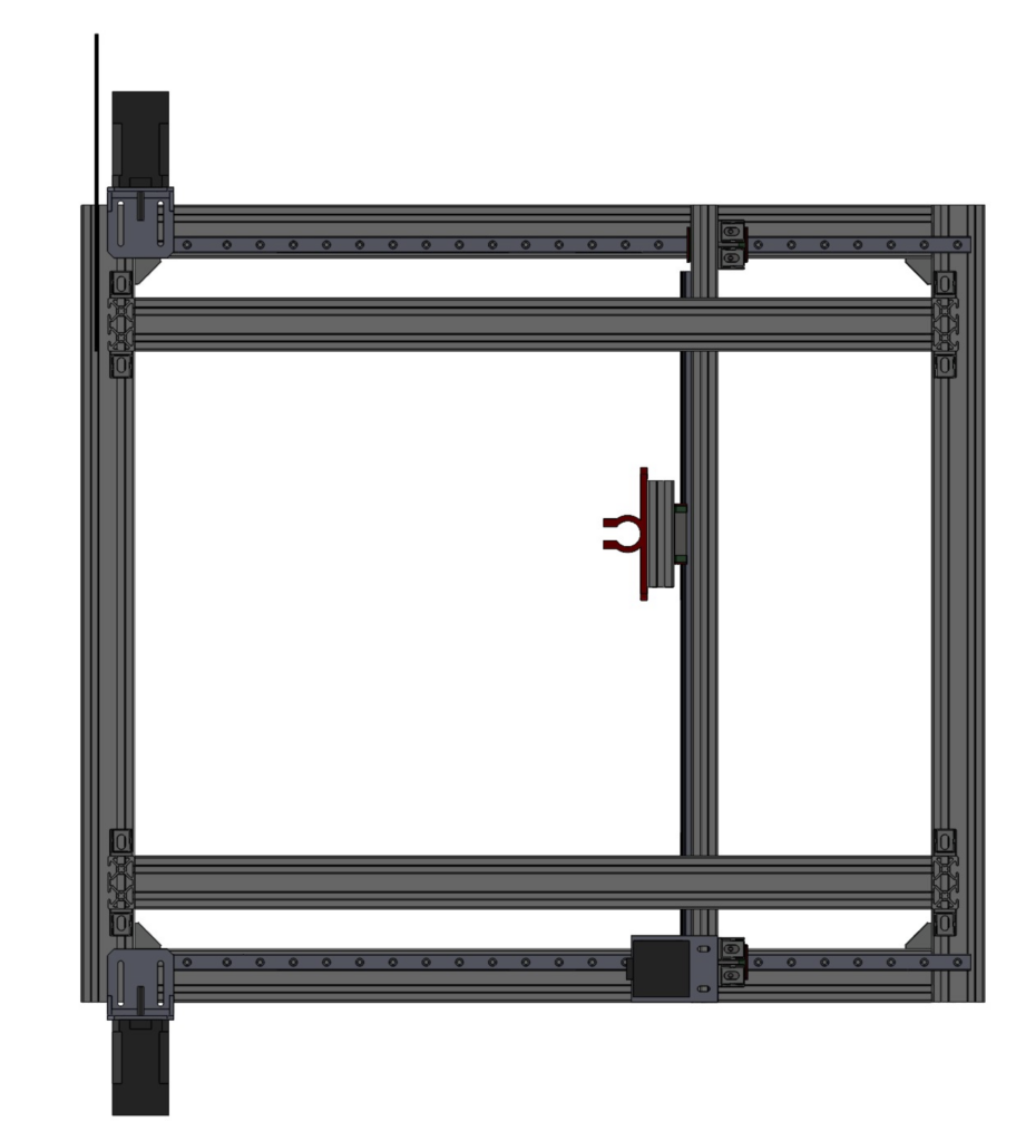
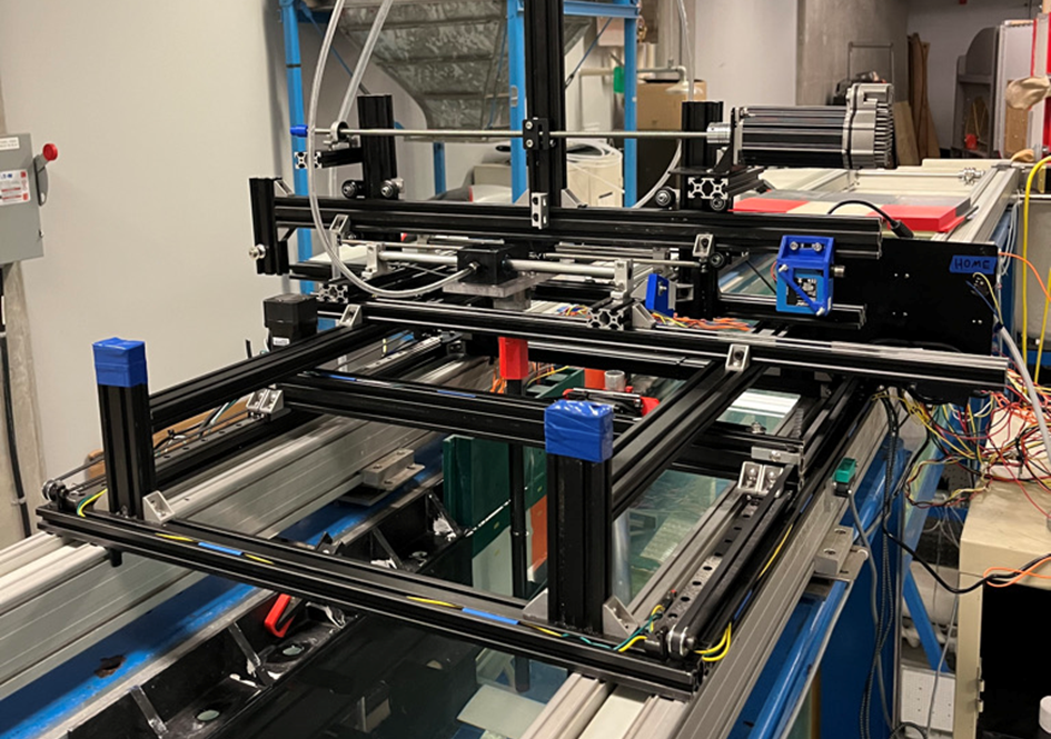
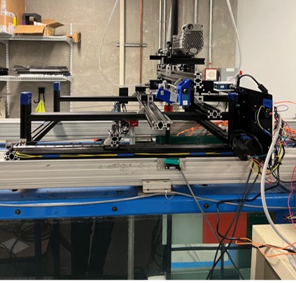
Actuator System
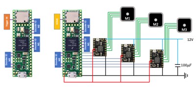
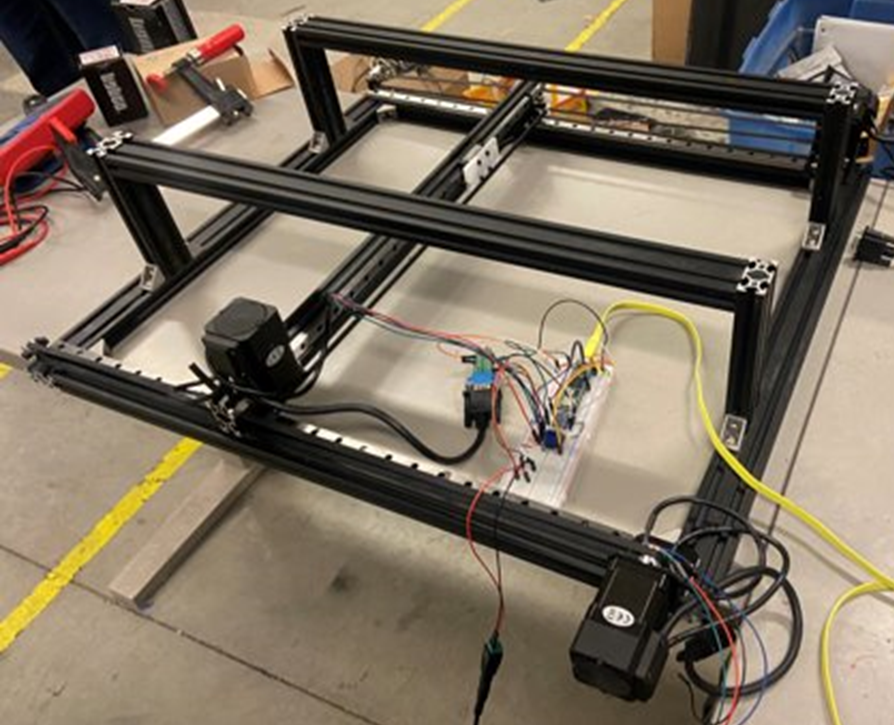
The actuator system is constructed of standard 2040 Aluminum T-Slot extrusion, and an assortment of angle brackets and fasteners. Three stepper motors with built in encoders. are used to actuate the system. These motors were selected primarily due to their strong holding torque, good positional accuracy, and because the optical encoders would allow for an easy implementation of a closed loop control system. A belt system is used to move the cylinder along linear square rails with two degrees of freedom.
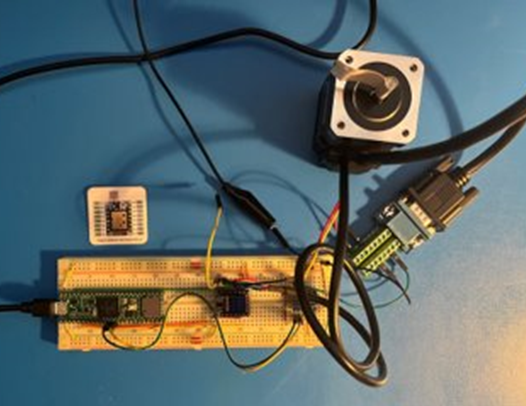
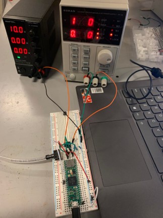
The electrical system on the actuator consists of 2 Teensy 4.1 Microcontrollers, which were selected due to their quantity of input and output ports and speed. The first microcontroller drives the motors. A custom written Arduino closed-loop firmware is designed to track the real time positional commands from the predictive controller. The second microcontroller sends the optical encoders data back to the predictive controller.
The software interface for the actuator system was written in Python, which sends and receives commands from the microcontrollers via serial connections.
Sensor System
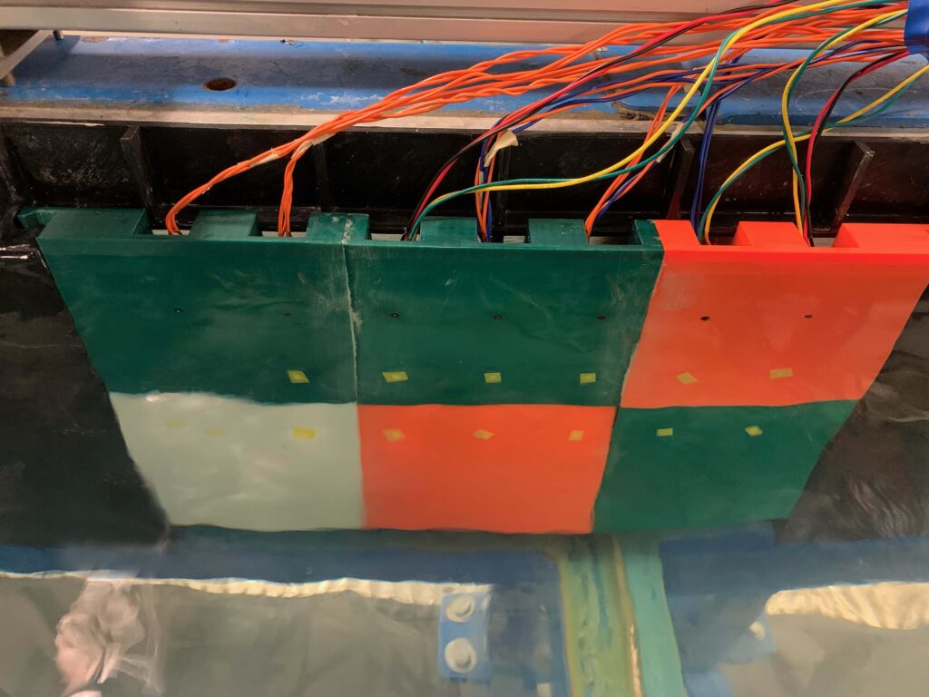
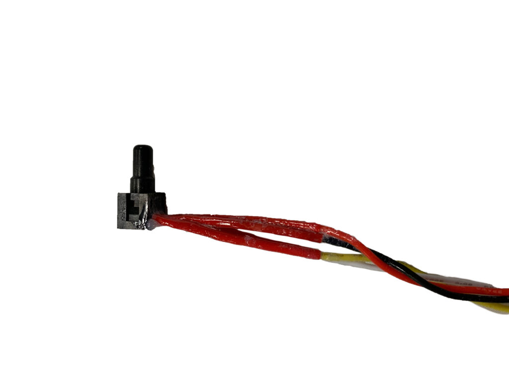
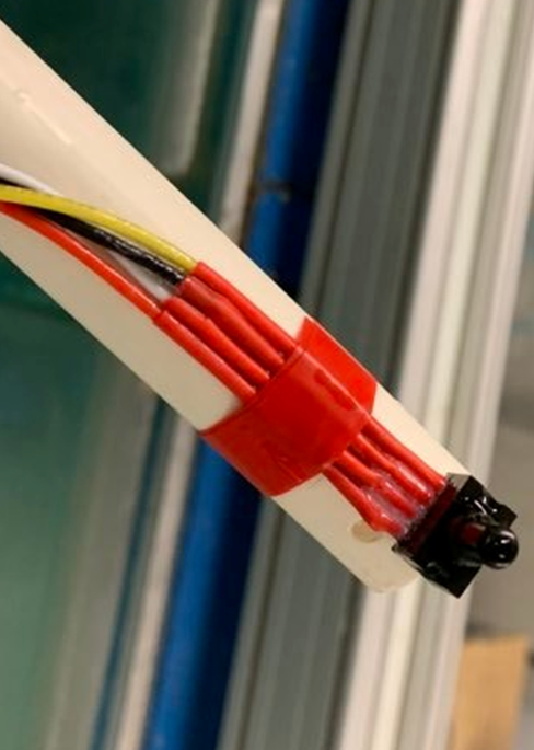
First, wet pressure sensors were chosen for the project as they give more direct and accurate pressure readings while in water. To have the sensors located in the channel, the connections between the wires and sensors needed to be waterproofed. This was done through layers of silicon conformal coating and heat shrink tubing.
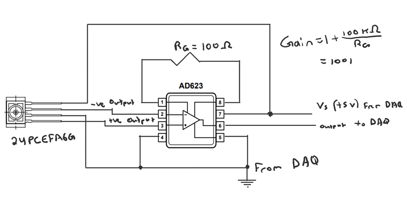
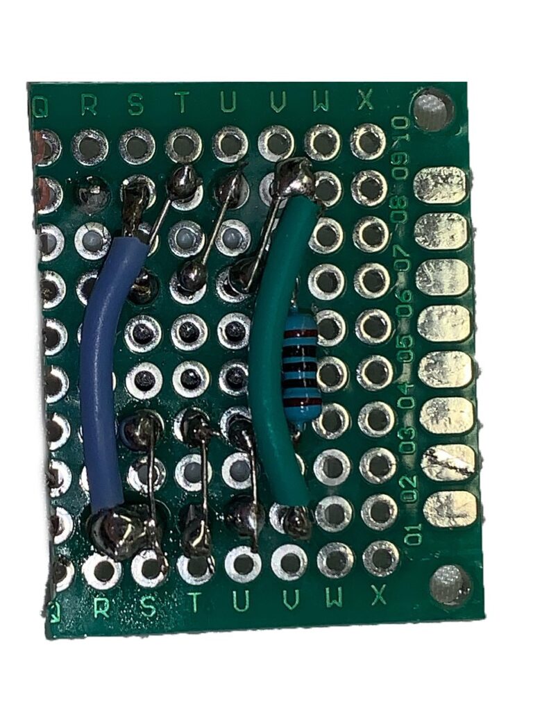
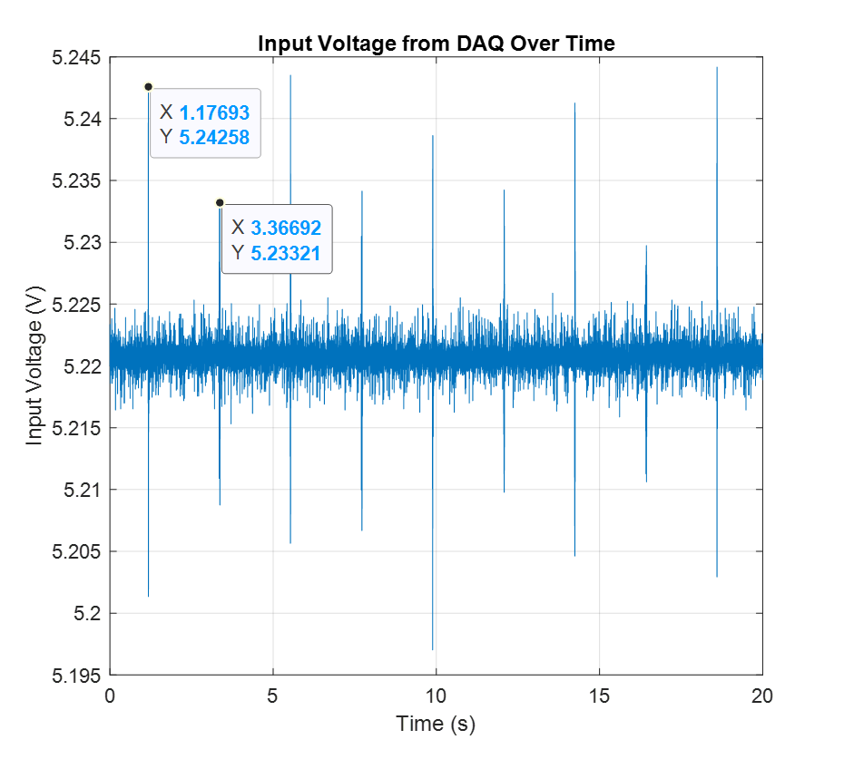
The chosen sensor then had to be amplified due to its low output voltage. To amplify the pressure signals, a compact amplification system using in-amps was designed to permit easily controlled gain via one resistor and quick connections to the sensors and DAQ. The gain of the amplification was chosen as 1001. This allowed for pressure changes as small as 0.03 Pa to be detected.
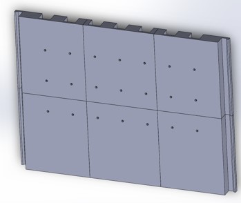
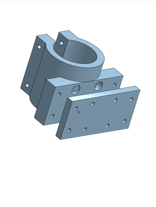
Next, the sensor housing array was designed in Solidworks, and 3D printed for quicker prototyping, and to assure the array did not interfere with our electrical signals from the sensors. The housing array has 7 sensing locations horizontally across the channel, and 3 vertically, allowing for customizable sensing configurations.
DESIGN SPECIFICATIONS
| Range of Motion | 340 mm x 406 mm |
| Minimum position error tolerance | 0.03 mm |
| Maximum movement speed | 188 mm/s |
| Maximum movement acceleration | 3500 mm/s2 |
| Maximum range of pressure readings | 0 – 3.4 kPa |
| Resolution of pressure readings | 0.03002 Pa/bit |
| Thickness of pressure array | 45 mm |
| Accuracy of model predictions | 0.033 N |
| Improvement in lift force over a stationary cylinder setup | Maximum of 25% |
Total Costs
| Item | Cost |
| Actuator System | $ 618 |
| Pressure Array System | $ 633 |
| Total | $ 1251 |
Partners and mentors
We would like to extend a special thanks to our mentors, sponsors, and instructors. Without them, this project would not have been possible.
We would like to thank Dr. Chris Morton and Chris O’Neill from the Laboratory for Turbulence Research in Aerodynamics and Flow Control (LTRAC) for sponsoring the project and providing their advice and guidance throughout the year. Additionally, we would like to thank Scott Webber for his help with the sensor array development and Calin Ghiroaga for his help with the neural network and model predictive control.
Finally, we would like to thank Dr. Alex Ramirez-Serrano and Danny Wong from the course instructional team for providing valuable feedback throughout the design process.
Our photo gallery
Computer Aided Design Models
Electronic Systems
Prototyping
Validation plots of the system
Final Design
References
- G. Assi. Mechanisms for flow-induced vibration of interfering bluff bodies. Ph.D. Dissertation, Department of Aeronautics, Imperial College London, London, 2009.
- “Vortex-induced vibration,” Wikipedia, 27-Mar-2021. [Online]. Available: https://en.wikipedia.org/wiki/Vortex-induced_vibration. [Accessed: April 3, 2022].
- C. Bingham, C. Raibaudo, C. Morton, R. Marnuzzi. Suppression of fluctuating lift on a cylinder via evolutionary algorithms: Control with interfering small cylinder. Physics of Fluids 30, 127104 (2018) https://doi.org/10.1063/1.5055016
