Project Category: Mechanical
Join our presentation
About our project
In the automotive world, dynamometers are used to measure the power produced by an engine at a specified revolutions per minute. For motorsport teams, dynamometers can be used to verify changes made to the engine to increase performance. One way to measure the power output of the engine is by measuring the torque produced at a specific revolution per minute. Our team aims to design and manufacture an inexpensive dynamometer setup to test and tune motorcycle engines with power outputs of up to 120 hp.
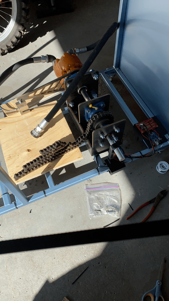
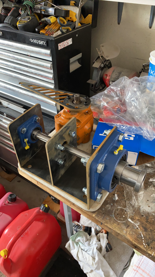
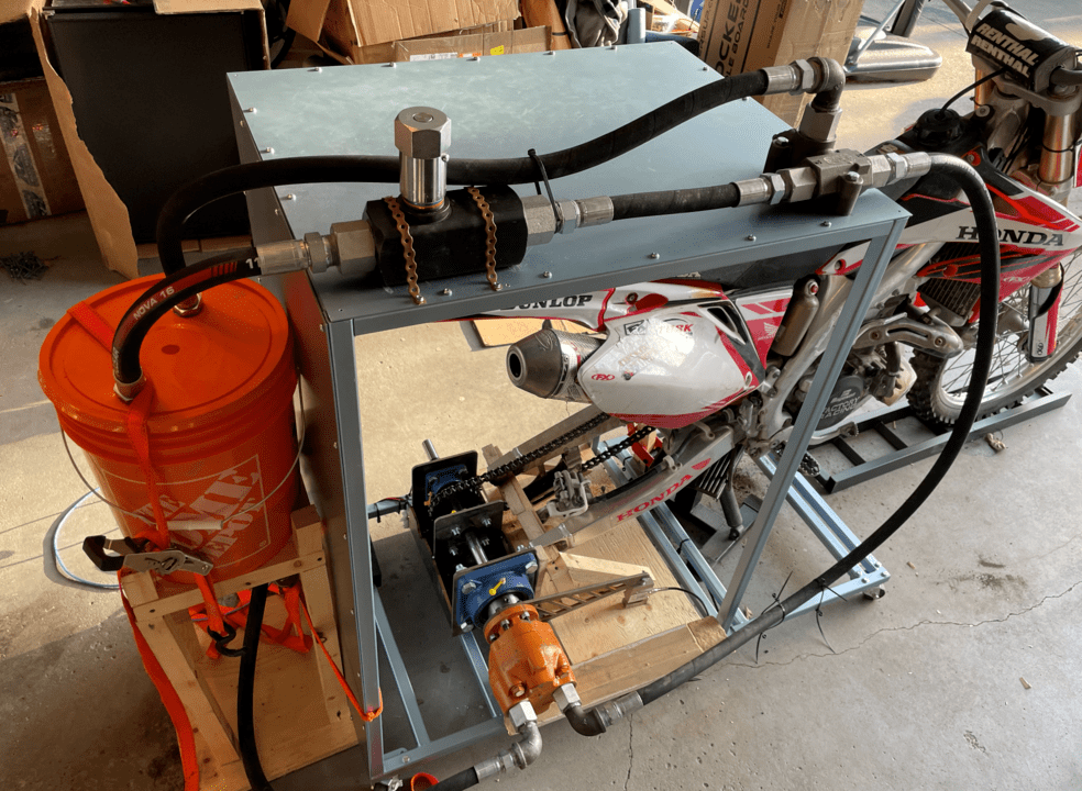
The dynamometer designed by the team is a hydraulic brake style dynamometer. This involves powering a hydraulic pump with the output of the engine, and using a flow control valve downstream of the pump to control the hydraulic pressure in the system. The amount of power required to power the pump is dictated by the amount of pressure in the system when the flow is restricted. This is a cost effective solution for lower horsepower engines.
This project has been sponsored by the University of Calgary’s Schulich Racing, a competitive student based team competing in FSAE (Formula Society of Automotive Engineers) competitions in North America. Total project cost: $3000 CAD
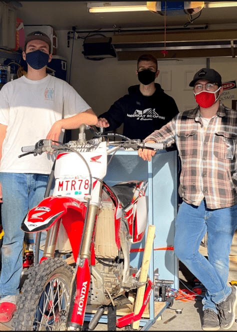
Meet our team members
Conrad Piatkowski 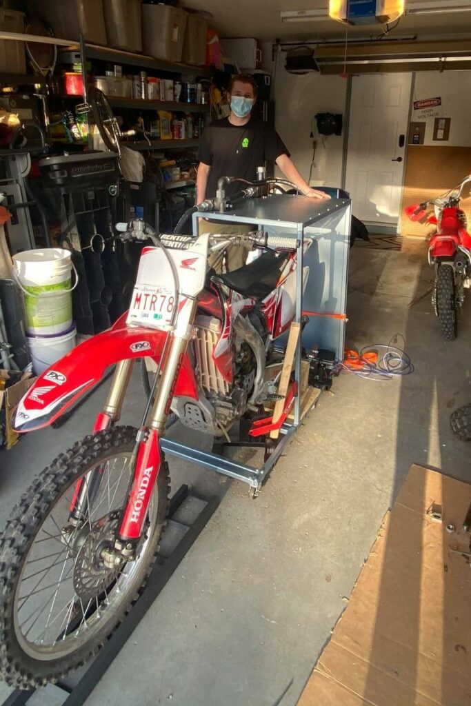
Josh Scotvold 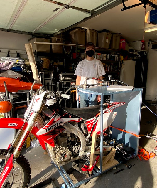
Olin Anderson 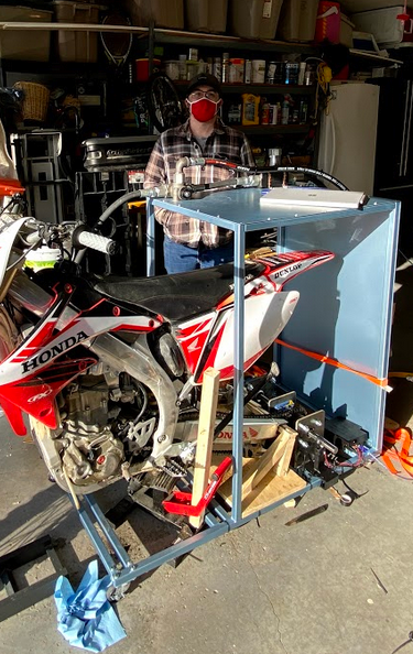
Tyler Sebastian
Details about our design
HOW OUR DESIGN ADDRESSES PRACTICAL ISSUES
Top teams in the formula student world spend countless hours testing and tuning their engines to get the highest performance they can with the restrictions set by the rules. These teams have either purchased dynamometers capable of testing their engines, or have student created setups through senior design courses. The sponsor of this project, the Schulich Racing FSAE team currently has no in-house method of tuning their engines. Presently, the team is required to travel to third party workshops with working dynamometer setups to do their tuning. This presents multiple problems for the team, with the most important issue pertaining to accessibility. In order to perform steady state tuning, dynamometers (dynos) must be run for long periods of time at several engine settings. Doing this at an outside shop requires not only a considerable payment to use their equipment, but also is a burden to move personnel and equipment from one shop to another.
This project aims to solve Schulich Racing’s problem of not having a readily available and easily accessible dyno by creating a functioning dynamometer. This project will allow in-house engine tuning and the justification of modifications done to increase the racecar’s horsepower.
WHAT MAKES OUR DESIGN INNOVATIVE
Hydraulic brake style dynamometers are relatively less used than more traditional setups, they are also usually better equipped at dealing with low horsepower setups. Our design pushes the limits of hydraulic brake setups, exceeding the maximum power numbers usually testable with this style. This is done while also maintaining safety and rigidity in the whole system.
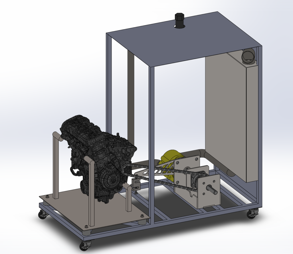
By designing this system to be able to withstand the high horsepower and torque numbers, the Schulich Racing team can test any engine they would potentially use in Competition. This includes the current engine (Yamaha R6) used in the interal combustion competitions, and also potential higher horsepower electric engines in the future. As the world moves towards sustainable electrical power, FSAE competitions will also follow. This was a major concern of the sponsor and our prototype can handle any potential FSAE caliber engine.
WHAT MAKES OUR DESIGN SOLUTION EFFECTIVE
Our design allows the user to test and tune engines with power outputs up to:
- 121 Horsepower
- 3000 Driveshaft RPM
- 47.7 lb-ft of Torque
Below is a sample dyno graph created from our prototype. The RPM is on the x-axis, and the horsepower and torque are on the left and right y-axis’ respectively.
HOW WE VALIDATED OUR DESIGN SOLUTION
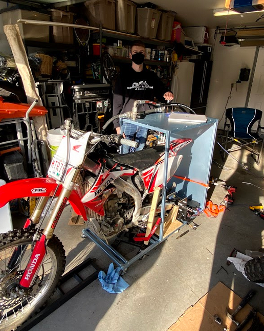
Once the prototype was fully manufactured, tests were performed on a CRF 450 dirtbike. In order for our design to be considered successful, horsepower and torque numbers would have to be reasonably close to tests performed on other dynamometer setups. After preliminary testing on the CRF 450, initial values were similar to other tests found.
More importantly, as dynamometer results often vary between setups the results of our tests must be repeatable. After multiple tests at the same setup, we were getting consistent power values for the CRF 450. This allows the user to make initial changes to an engine, and return to that testing configuration to make more changes.
Every critical component of the prototype was tested using valid engineering methods. This includes Finite-Element-Analysis and using governing equations with design values set by our major components.
FEASIBILITY OF OUR DESIGN SOLUTION
The feasibility of this design is shown in it’s cost effectiveness. For the horsepower ranges the prototype can test, this is an extremely low budget setup. Other dyno setups require complex machined parts, or components and systems that require a large amount of electrical power. This design is powered solely by the attached engine, and all parts are easily attainable and manufacturable
Schulich Racing is a university-based team with a roster that undergoes changes on a yearly basis. Senior members graduate and leave the roster, while brand new students are taken on by the team. The system must be simple enough that any member can familiarize themselves with it and operate it. The prototype created is very user friendly, a short operating guide was created so any member of the Schulich Racing team can learn how to use the prototype without much prior knowledge.
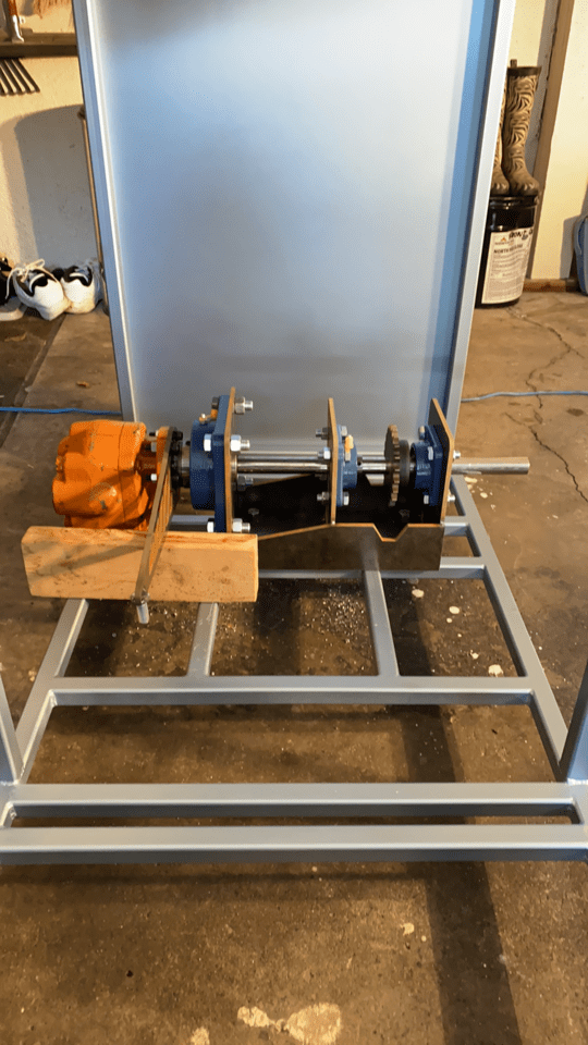
Due to the nature of the COVID-19 pandemic, and it’s effect on available materials and manufacturing capabilities the prototype had to be designed with these constraints in mind. All of the structural components were made with mild steel, due to it’s availability, price and material properties. Since the access to machining services was very limited, every single major component of the driveline and hydraulics system had to be sourced from known suppliers. The design of the prototype was done so that it would take very little machining to be manufactured.
Acknowledgements
The team behind the small engine dynamometer would like to thank Dr. Phillip Egberts and our TA Danny Wong for their valuable advice and criticisms. We would also like to thank our friends who helped us source manufacturing and parts.