Project Category: Mechanical
Join our Live Presentation and ask Questions!
About our Project
Small satellite launch vehicles are rockets designed to carry relatively small mass payloads, typically less than 2000 kg, into low earth orbit (LEO). Launching a single satellite into space can cost anywhere from 10 to upwards of 400 million dollars, on top of the already extreme cost of developing a satellite. Our group aims to optimize launch vehicle parameters such as the flight path trajectory and rocket engine configuration for an arbitrary launch vehicle design. Through complex launch simulations and optimization loops, the parameters needed to attain a more efficient and cost-effective launch vehicle will be determined.
We chose to optimize the flight trajectory path as well as the number and type of commercial engines per rocket stage for several reasons:
- A more efficient trajectory allows the launch vehicle to reach the same orbit with either less fuel or a heavier payload.
- By using relevant commercial engine data, we can determine the specific engine type and number of engines to be used in each stage of the rocket. This will allow us to calculate the combination that reaches orbit with the least amount of fuel remaining.
To support these objectives, we will optimize the rocket velocity, height, and residual fuel at orbital insertion. Additionally, we are assuming the majority of variables, such as payload mass (500kg), as constants between iterations.
To accomplish our goal, the group utilized a newly developed University of Calgary software called “MAPLEAF” to be able to conduct our analysis and expand on its existing functionalities. By using this software as a base rocket flight simulation framework, the group developed and incorporated new guidance and navigation methods, trajectory control, commercial engine data implementation, and optimization algorithms. Following an optimized design loop that iterates through a list of commercially available engines, an optimal path to orbit with set end conditions will be determined which include an output of launch vehicle design parameters, the specific engine type, and number of engines per stage.
Brief Video of our Project
Meet Our Team

Jackson is a mechanical engineering student and interned as a reliability engineer for heavy mining equipment with dominion diamond mines. He is passionate about amateur rocketry and has been a member of the Student Organization for Aerospace Research at UofC for 3 years designing propulsion systems for hybrid rockets.

Sergio is a mechanical engineering student with previous experience as a project manager and utilities designer intern at ATCO. He is passionate about renewable energy projects and mechatronics engineering. Sergio has previously been a member of Schulich Aerodesign with a focus on performing simulations.

Daniel is a mechanical engineering student with internship experience as an exploitation engineer at Crescent Point. Daniel spends his free time volunteering at homeless shelters, music centers, and mental health clinics. Daniel is a first year student mentor and volunteers with the UofC’s Covid-19 support program.

Alex is a mechanical engineering student with internship experience as a piping engineer at CNRL. He is powertrain lead for the UofC Formula SAE engineering team. Alex is well versed in design and manufacturing.

Paul is a mechanical engineering student with internship experience as a product engineer at Shawcor. After graduation Paul hopes to pursue a career in aviation or renewable energy.
Details About our Design
HOW OUR DESIGN ADDRESSES PRACTICAL ISSUES
Our design focuses on solving several practical issues currently facing the small satellite industry and aims to provide recommendations for lowering launch costs. Additionally, our project is aimed at progressing the tools available to researchers in the field of rocketry. For the most part, small satellites are launched into low earth orbit aboard rockets that were designed 20 years ago with less information than we currently have today. Therefore, using cutting edge software techniques, we demonstrate an optimal solution for both trajectory planning and engine configuration of a generic two stage LEO rocket.
Optimizing flight trajectory maneuvers and commercial engine configuration will have the biggest effect in regards to lowering launch costs of these rockets.
The particular parameters optimized by our cost functions are the orbital velocity, orbital height, and remaining fuel at orbital insertion.
TECHNICAL BACKGROUND INFORMATION
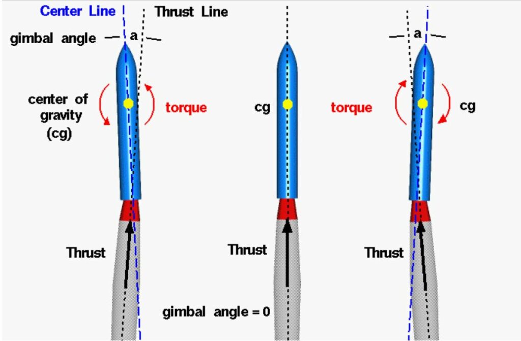
Our design required coding additional functionalities into MAPLEAF to facilitate advanced guidance navigation and control (GNC) using thrust vectoring (TVC). As seen in the figure below, TVC manipulates the nozzle angle in order to steer the rocket.
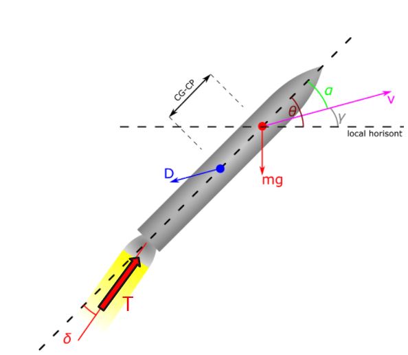
Below is the free body diagram for a generic rocket. The main forces involved with rocket flight are drag, gravity, and thrust. MAPLEAF keeps track of these forces and at each time step and updates the 6 degrees of freedom associated with a right handed coordinate frame.
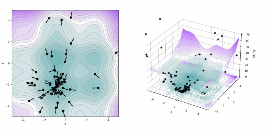
We used an optimization algorithm called particle swarm in our project. This method works by iteratively assessing the fitness of potential solutions, known as “particles” and outputting the solution that minimizes user defined cost functions. Note, cost functions are just a mathematical statement in which the parameters to be optimized are represented and deviation from the desired behavior is penalized (i.e. a larger value of the function).
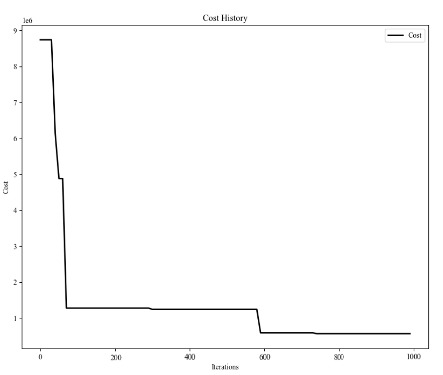
Below are the two cost functions used to optimize the trajectory and propulsion systems. The trajectory is evaluated based on the velocity and height of orbital insertion. Propulsion/engine performance is evaluated on the amount of fuel remaining at orbital insertion.
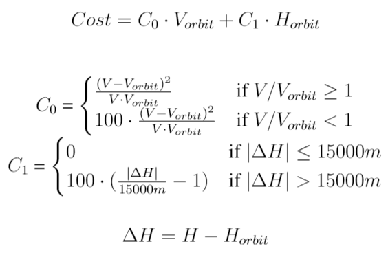
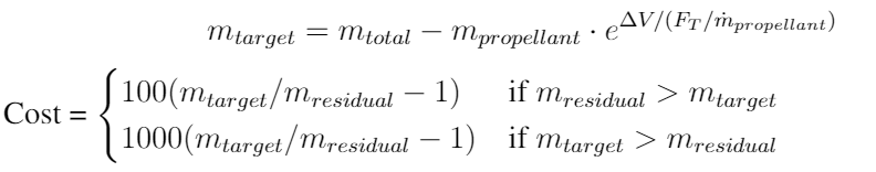
The below figure is the combined cost function for both trajectory and propulsion systems. As seen in the figure, the cost is minimized after a short number of iterations.
COMMERCIAL ENGINE DATA CONSOLIDATION
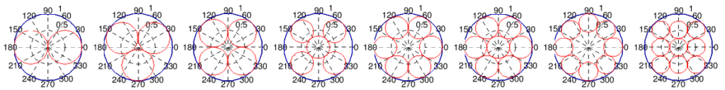
In order to optimize the propulsion system we collected a sample of 37 commercial rocket engines and their related parameters as seen in the table below. We iteratively simulated different combinations of engines, the diameter of each stage was determined using an optimal circle packing derivation seen in the figure below as well as an assumed stage length to diameter ratio derived from dimensionless trends seen below.
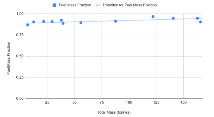
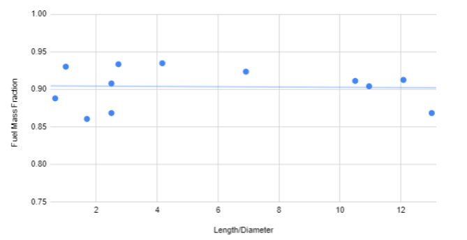
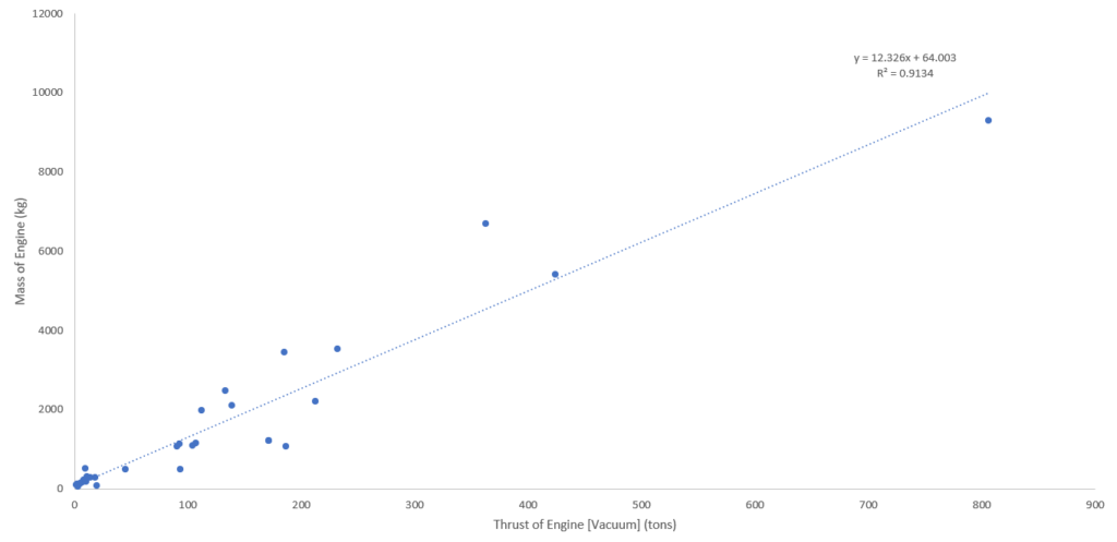
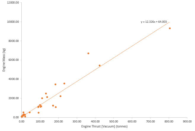
From the information displayed in the below table, we were able to construct several trends that facilitated data imputation in the event of missing data fields.
| Engine | Vehicle | Propellant | Engine Max Diameter (m) | Fuel Density (kg/m^3) | Oxidizer Density (kg/m^3) | Oxidizer:fuel ratio | Specific impulse (s) [Vacuum] | Thrust (tonnes) [Vacuum] | Mass (kg) |
| 11D58MF | Zenit 3SL US | CH4 / LOX | 1.17 | 422.80 | 1141.00 | 2.48 | 356.00 | 8.50 | 230.00 |
| Aeon 1 | Terran 1 | CH4 / LOX | 0.55 | 422.80 | 1141.00 | 3.50 | 310.00 | 8.85 | 173.03 |
| Aeon 1 Vacuum | Terran 1 | CH4 / LOX | 2.10 | 422.80 | 1141.00 | 3.50 | 360.00 | 12.89 | 222.84 |
| Aestus | Ariane 5 EPS | N2O4 / MMH | 1.31 | 1442.46 | 880.00 | 2.05 | 324.00 | 3.00 | 111.00 |
| AJ10-118K | Delta-ll 2nd stage | N2O4 / MMH | 1.70 | 1442.46 | 880.00 | 1.80 | 319.20 | 4.46 | 127.40 |
| AJ-10-190 | Space Shuttle | N2O4/MMH | 0.84 | 1442.46 | 880.00 | 1.65 | 316.00 | 2.72 | 118.00 |
| AJ26-59 | K-I 1st stage | RP-1 / LOX | 1.50 | 810.00 | 1141.00 | 2.59 | 331.30 | 171.62 | 1222.00 |
| HM-7B | Ariane 2 | LH2 / LOX | 0.99 | 70.85 | 1141.00 | 5.00 | 446.00 | 6.61 | 165.00 |
| J2-X | SLS US | LH2 / LOX | 3.05 | 70.85 | 1141.00 | 5.50 | 448.00 | 133.36 | 2472.10 |
| Kestrel | Falcon 1 US | RP-1 / LOX | NA | 810.00 | 1141.00 | 2.35 | 325.00 | 2.83 | 52.00 |
| LE-5B | H-ll US | LH2 / LOX | NA | 70.85 | 1141.00 | 5.00 | 449.00 | 14.00 | 285.00 |
| LE-7A | H-ll 1st Stage | LH2 / LOX | NA | 70.85 | 1141.00 | 5.90 | 440.00 | 112.00 | 1980.00 |
| LR-91-5 | Titan II 2nd stage | N2O4 / UDMH | 1.68 | 1442.46 | 793.00 | 1.80 | 316.00 | 44.87 | 500.00 |
| Merlin 1D FT | Falcon 9 B5 | RP-1 / LOX | 1.25 | 810.00 | 1141.00 | 2.17 | 304.00 | 93.20 | 490.00 |
| Merlin Vacuum 1D | Falcon 9 B5 | RP-1 / LOX | 3.55 | 810.00 | 1141.00 | 2.17 | 342.00 | 100.03 | 1297.02 |
| NK-33A (AJ26-62) | Antares 100 | RP-1 / LOX | 1.50 | 810.00 | 1141.00 | 2.59 | 331.30 | 171.31 | 1222.00 |
| RD-0120 | Buran orbiter | LH2 / LOX | 2.42 | 70.85 | 1141.00 | 6.00 | 455.00 | 184.88 | 3450.00 |
| RD-0146 | Angara US | LH2 / LOX | 1.25 | 70.85 | 1141.00 | 6.00 | 463.20 | 9.99 | 502.00 |
| RD-107A | Sojuz Boosters | CH4 / LOX | NA | 422.80 | 1141.00 | 2.47 | 320.20 | 104.01 | 1090.00 |
| RD-108A | Sojuz Core | CH4 / LOX | NA | 422.80 | 1141.00 | 2.47 | 320.60 | 90.40 | 1075.00 |
| RD-120 | Zenit 2nd stage | CH4 / LOX | 1.95 | 422.80 | 1141.00 | 2.58 | 350.00 | 93.00 | 1125.00 |
| RD-171M | Zenit 1st stage | CH4 / LOX | NA | 422.80 | 1141.00 | 2.63 | 337.00 | 805.99 | 9300.00 |
| RD-180 | Atlas 1st stage | CH4 / LOX | NA | 422.80 | 1141.00 | 2.72 | 337.80 | 424.00 | 5400.00 |
| RD-191 | Angara | RP-1 / LOX | 1.45 | 810.00 | 1141.00 | 2.60 | 337.00 | 212.60 | 2200.00 |
| RD-276 | Proton-M | N2O4 / UDMH | 1.50 | 1442.46 | 793.00 | 2.67 | 315.80 | 186.80 | 1070.00 |
| RD-861K | Cyclone-4M | N2O4 / UDMH | 1.53 | 1442.46 | 793.00 | 2.41 | 330.00 | 7.91 | 194.00 |
| RD-869 | VEGA AVUM | N2O4 / UDMH | 0.30 | 1442.46 | 793.00 | 2.00 | 314.70 | 0.25 | 67.15 |
| RL10A-4 | Atlas V US | LH2 / LOX | 1.17 | 70.85 | 1141.00 | 5.50 | 451.00 | 10.12 | 181.10 |
| RL10B-2 | Delta-IV US | LH2 / LOX | 2.15 | 70.85 | 1141.00 | 5.88 | 465.50 | 11.22 | 301.20 |
| RS-27A | Delta II 1st stage | RP-1 / LOX | 1.70 | 810.00 | 1141.00 | 2.25 | 302.00 | 107.50 | 1146.70 |
| RS-68A | Delta IV | LH2 / LOX | 2.44 | 70.85 | 1141.00 | 5.97 | 411.00 | 362.87 | 6686.00 |
| RS-72 | Ariane 5 EPS evol. | N2O4 / MMH | 1.30 | 1442.46 | 880.00 | 1.90 | 340.00 | 5.65 | 138.00 |
| S5.92 | US Fregat | N2O4 / UDMH | 0.84 | 1442.46 | 793.00 | 2.00 | 327.00 | 19.99 | 75.00 |
| S5.98 | US Breeze | N2O4 / UDMH | NA | 1442.46 | 793.00 | 2.00 | 325.50 | 2.00 | 95.00 |
| SSME | Shuttle orbiter | LH2 / LOX | 2.44 | 70.85 | 1141.00 | 6.03 | 452.30 | 232.37 | 3526.20 |
| Vinci | Ariane 6 | LH2 / LOX | 2.20 | 70.85 | 1141.00 | 0.00 | 467.00 | 18.35 | 280.00 |
| Vulcain 2 | Ariane 5 | LH2 / LOX | 2.10 | 70.85 | 1141.00 | 6.10 | 431.00 | 138.58 | 2100.00 |
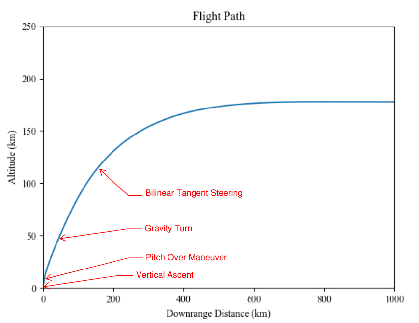
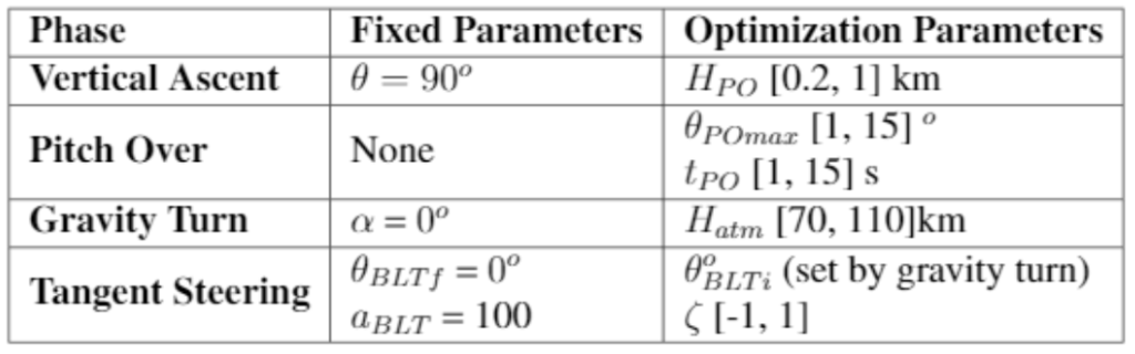
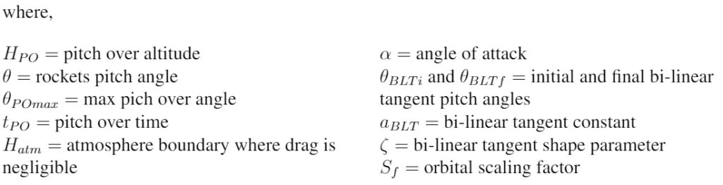
We chose to implement a bilinear tangent steering trajectory for our guidance, navigation, and control as shown in the figure below.
In the table below are the trajectory parameters (constants and ranges) used in the simulations.
FINAL SIMULATION RESULTS
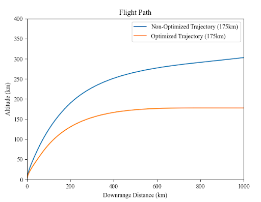
The main results of our iterative simulations demonstrate the effectiveness of our design solution. Below we have a non-optimal and optimal solution as determined by our simulation. It is clear that the non-optimal trajectory wastes fuel do to it’s elliptical nature and overcorrection needed to readjust to a circular orbit.
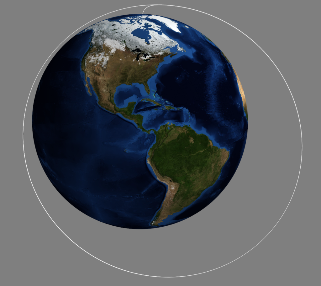
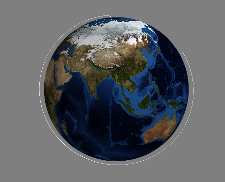
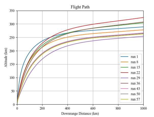
Below are examples of how the flight trajectory changes between iterations. For ease of comparison, the left chart shows the most optimal path and a random non-optimal path to compare and contrast. It is clear that the optimized trajectory enters orbit at zero rocket pitch angle, while the non-optimal solution pitch is non-zero, meaning there will be further fuel spent readjusting in order to obtain a circular orbit.
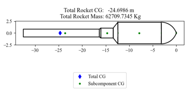
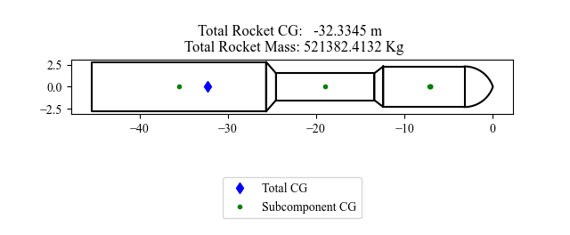
Additionally, below are examples of the rocket shape for a non-optimal and optimal rocket configuration. It is obvious that the non-optimal solution would be a poor performer since it is generally desired to have the majority of thrust (and thus a large engine or large number of smaller engines) in the first stage as evident by every commercial rocket ever flown. Also, from a structural standpoint, the non-optimal solution would most likely be top heavy and require more fuel to correct for pitching, thus lowering it’s efficiency. The optimal solution looks very similar to modern rockets like the Falcon 9, Terran 1, and Electron, where a large number of medium sized engines are used in the first stage and a single, large engine is used in the second stage.
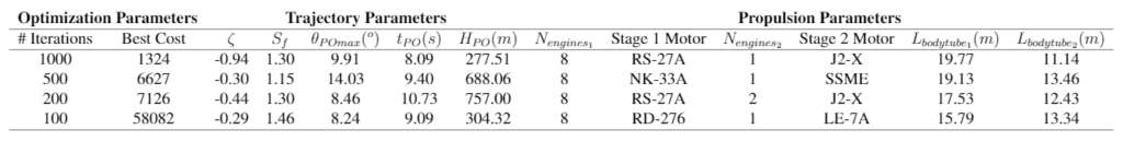
In the table below is a complete summary of the rocket parameters of our simulations most optimal solution. N is the number of engines for a particular stage, and L is the stage length. It is clear the number of iterations performed is inversely proportional to the cost function.
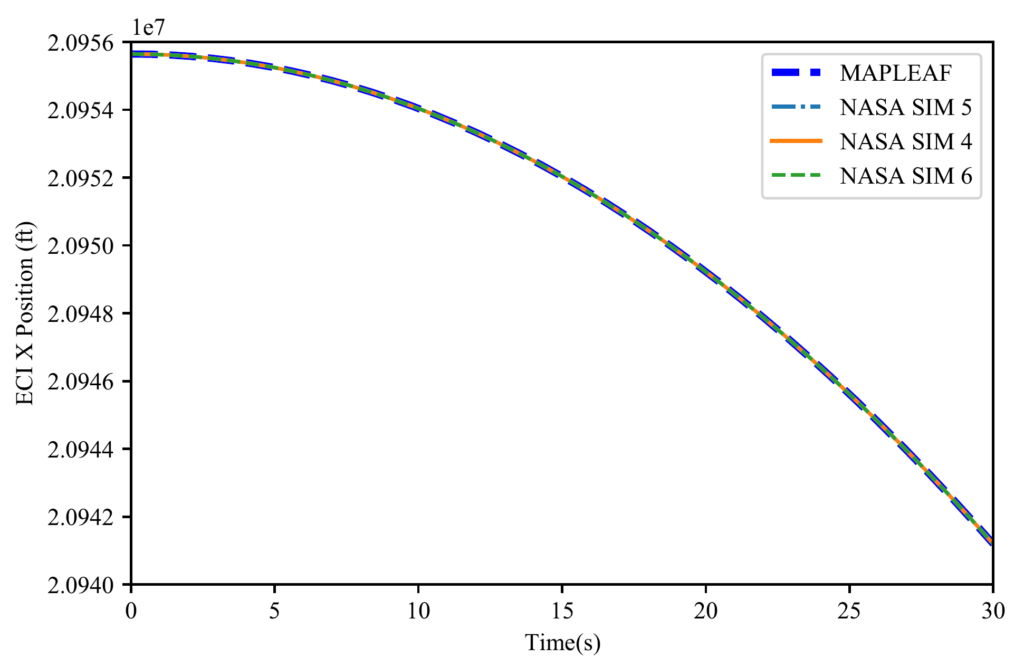
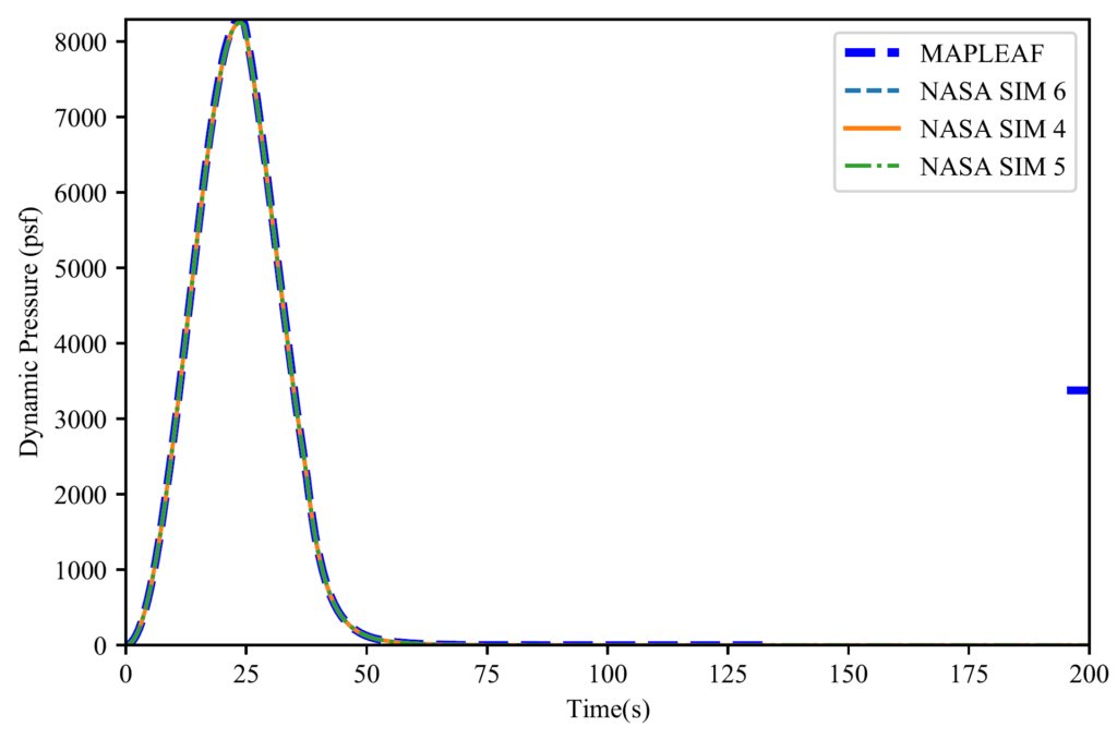
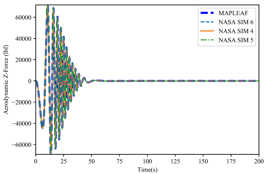
HOW WE VALIDATED OUR DESIGN SOLUTION
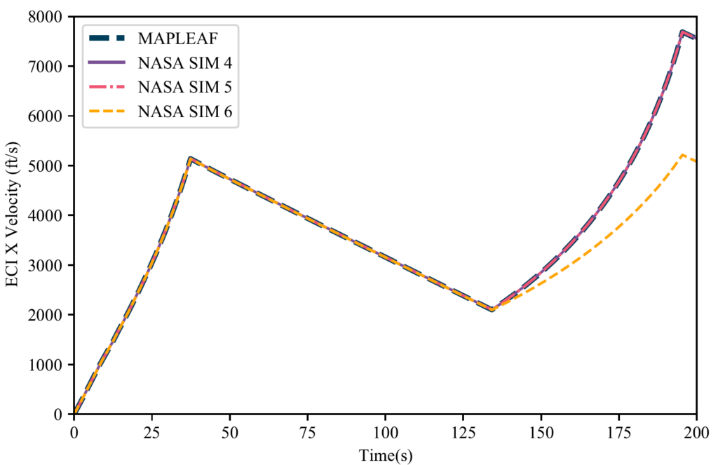
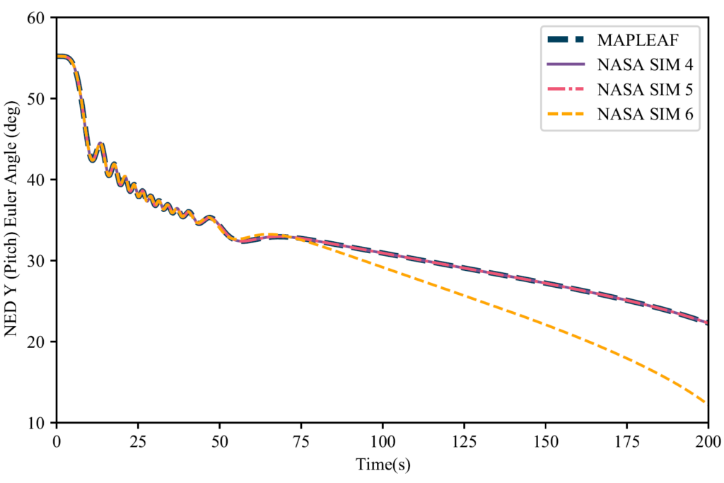
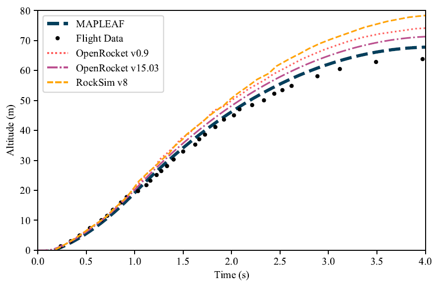
Firstly, MAPLEAF as a simulation package has been verified using NASA curated test data as seen in the figures below. However, since we are simulating rocket designs there are currently no other programs available to civilians that can verify our orbital simulations for their validity. Additionally, it is not feasible to build a prototype to test our results due to time and budget restrictions.
Therefore, the only method we have at our disposal for validation are real world rockets that have flown into space. By looking at commercial rockets, we see that the most modern designs including Electron, Falcon 9, and Terran 1 use 9 engines in their first stage and 1 engine in their second stage. Our optimal solution predicted 8 engines for the first stage and 1 engine for the second. Therefore, we conclude the optimization simulation results were a success and are consistent with modern rocket designs. However, they do not fully validate our simulations or procedures. In order for full validation, we would need access to confidential flight logs to compare simulation performance against real flights.
FEASIBILITY OF OUR DESIGN SOLUTION
To determine the optimized results, we first started by creating simulations of the Falcon 9 rocket with a predefined trajectory and comparing our simulation results, such as engine burn time and stage separation altitude, to available data. We found the assumptions in the analysis were reasonable as the simulation results closely matched the Falcon 9 telemetry data.
We then developed the trajectory optimization using a 4-part trajectory and a cost function which we derived using the rocket velocity and altitude as parameters. We then tested the trajectory optimization by using flight path data from the Falcon 9 and found our results correlated highly. From this, we were able to be confident the trajectory optimization was working correctly and was producing results which matched real world data.
Finally, we developed the propulsion optimization using body tube length, number of motors and type of motors for each stage. The stage diameter was determined using circle packing efficiency to determine the minimum body tube diameter. The model was verified by setting up a study using a limited range of motors where the outputs were expected to be similar to the Falcon 9. The optimized results from this study output both the Falcon 9 engines along with similar first and second stage body tube lengths and diameters which verified our model.
We tested the trajectory and propulsion optimizations and compared the results to Falcon 9 data which showed a high correlation; therefore, we have a high confidence that our models are correct and will produce high fidelity results.
Although our project aims to determine the optimal small satellite launch vehicle trajectory and propulsion parameters, we are limited by computation power. To determine the true optimal parameters, the search space needs to be infinite; however, since this is not possible, we do expect errors in our results. Furthermore, there may be several other combinations of parameters which would yield similar optimized results but may not have been found due to random errors. From our final results, we found the cost to be inversely proportional to the number of iterations which is aligned to what is expected. With additional time and computational power, we would be able to produce several optimized rocket designs for small satellite launch vehicles.
Partners and mentors
We want to thank several people for their support and guidance. Firstly, we thank Mr. Henry Stoldt for his time spent helping us understand, further develop, and debug the MAPLEAF software he created. We would like to thank Dr. Craig Johansen, Mr. Troy Messinger, and Mr. Declan Quinn for supplying their advice and expertise. Lastly, we thank Dr. Philip Egberts and Mr. Danny Wong for their regular feedback and constructive criticism throughout our capstone project.
Our photo gallery
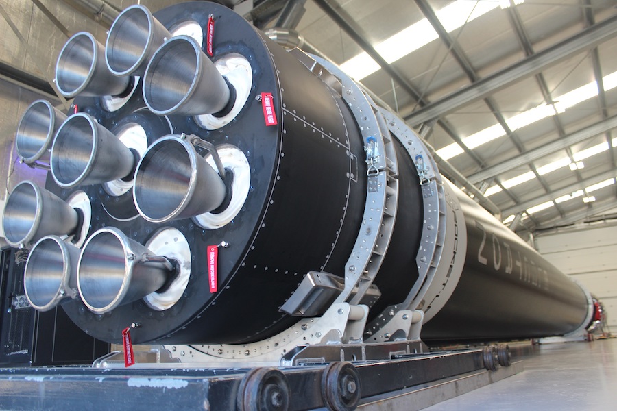
REAL WORLD ROCKET FIRST STAGE ENGINE CONFIGURATIONS
These figures below demonstrate the trend of modern rockets to use a large number of medium sized engines in their first stage juxtaposed with older designs which utilized a few very large engines in their first stage.
Electron Rocket First Stage (9 Engines)
First Launch – 2018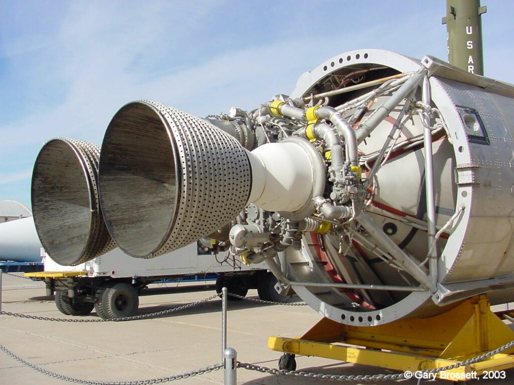
Titan II Rocket First Stage (2 Engines)
First Launch – 1962
