Project Category: Mechanical
Join our presentation
About our project
Small-scale unmanned aerial vehicle (UAV) platforms are becoming an increasingly viable solution for conducting flight and fluid mechanics research in the transonic and supersonic regimes. This project built upon an existing airframe design of a UAV developed by the Aerospace and Compressible Flow Research Group at the University of Calgary (AERO-CORE), in partnership with Atlantis Research Labs (ARL). Over the duration of ENME 501/502, the team conducted a detailed design of both internal and external structures, including a high-level composite re-design of the UAV structure elevating its capabilities to theoretically achieve supersonic flight. The team completed several design iterations which included a structural re-design, computer-based verification, and manufacturing of a carbon fiber half-scale of the UAV wing.
Meet our team members
Timothy Chang

Bradley Dezall

Rebecca Fyfe

Mina Mina

Keilan Pieper
Kaiden Powell

Download our Poster
Details about our design
HOW OUR DESIGN ADDRESSES PRACTICAL ISSUES
Small-scaled UAVs are considered to be ideal low-cost platforms used for testing of aviation technologies, such as alternative propulsion, flow control, and sonic boom minimization [1]. Typical research testing for such systems is primarily based on supersonic wind tunnels, which are energy intensive and costly [2]. In addition, these tunnels require uncertainty quantification, flow speed control, and run time control [2,3,4,5]. These disadvantages are burdensome, impacting the industry to the extent that even NASA has been slowly moving away from wind tunnels [6]. It is for these reasons that our design holds its value. This capstone leads the development in the supersonic UAV field and expands the horizons for research testing at these high-speeds.
WHAT MAKES OUR DESIGN SOLUTION EFFECTIVE
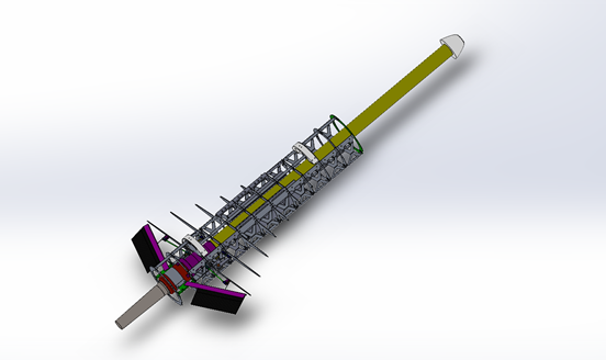
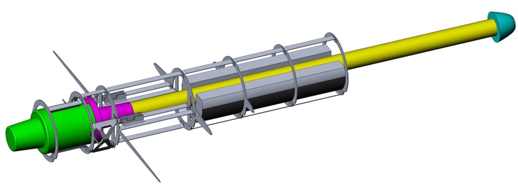
Internal Features
Our design features a minimalistic interior structure – optimized over several iteration based on continuous loading studies on ANSYS Static Structural. This minimalistic design, in combination with ANSYS testing results, indicate the possibility of transitioning to a unibody design in the future.
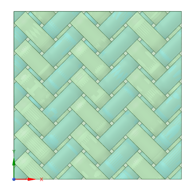
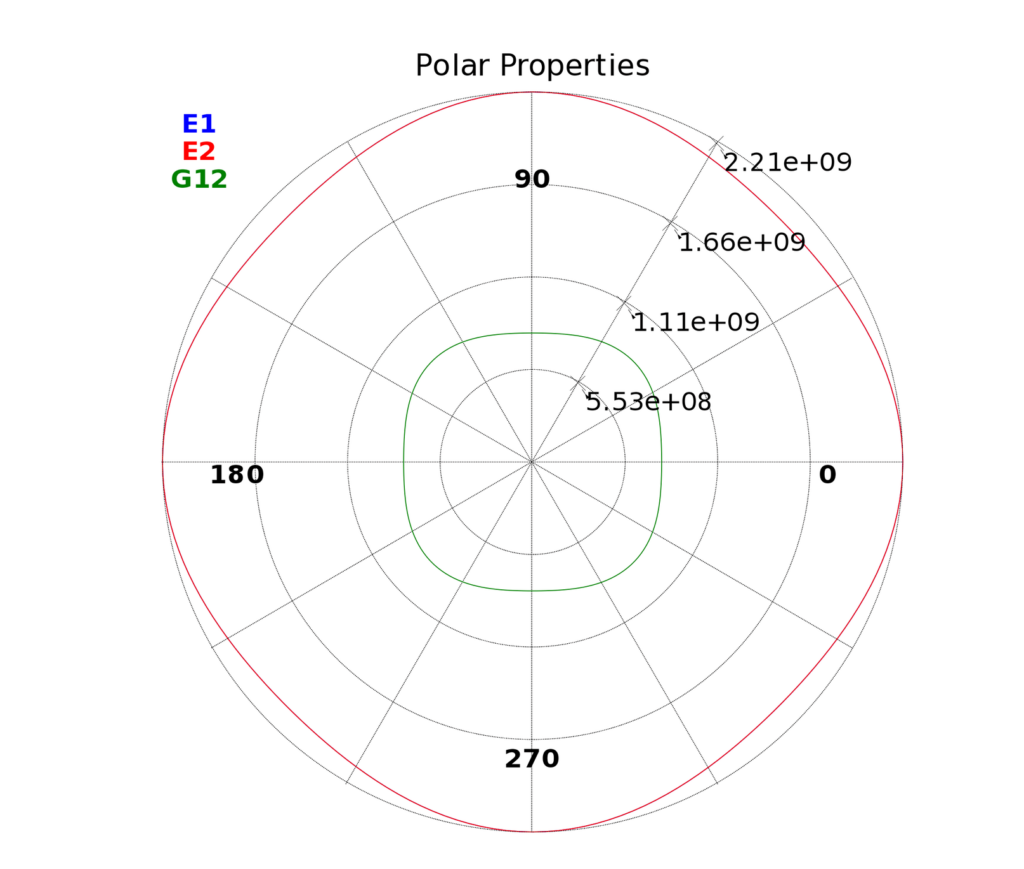
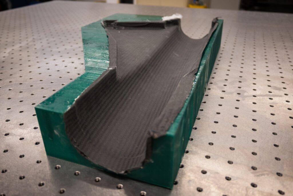
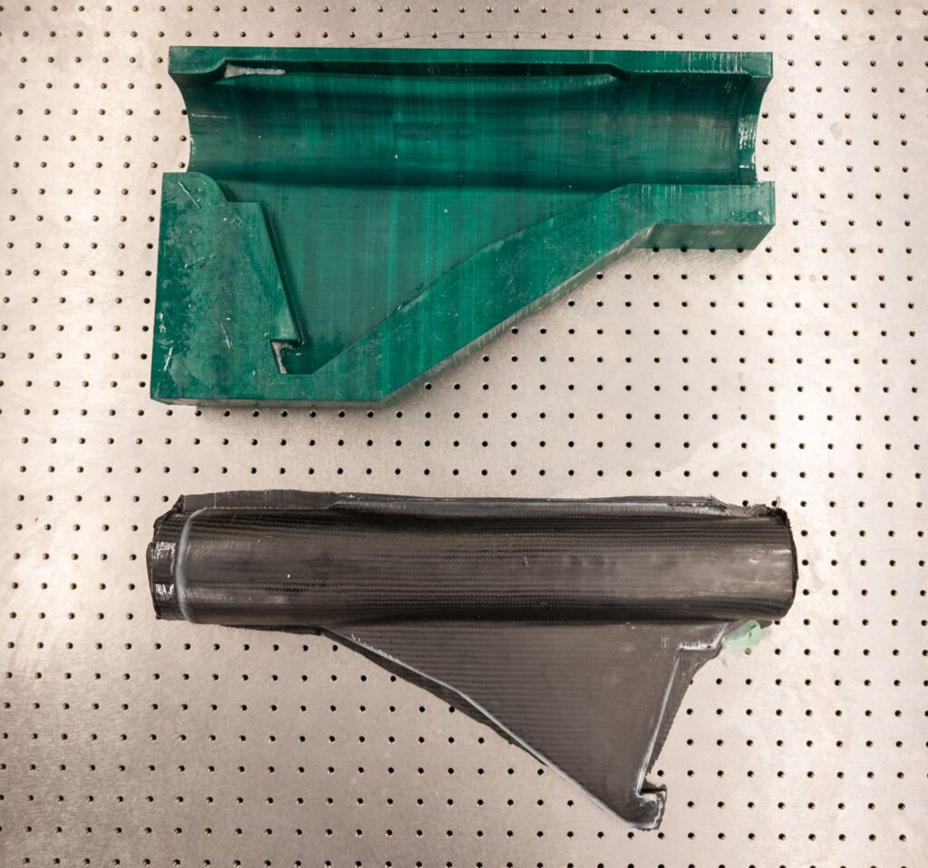
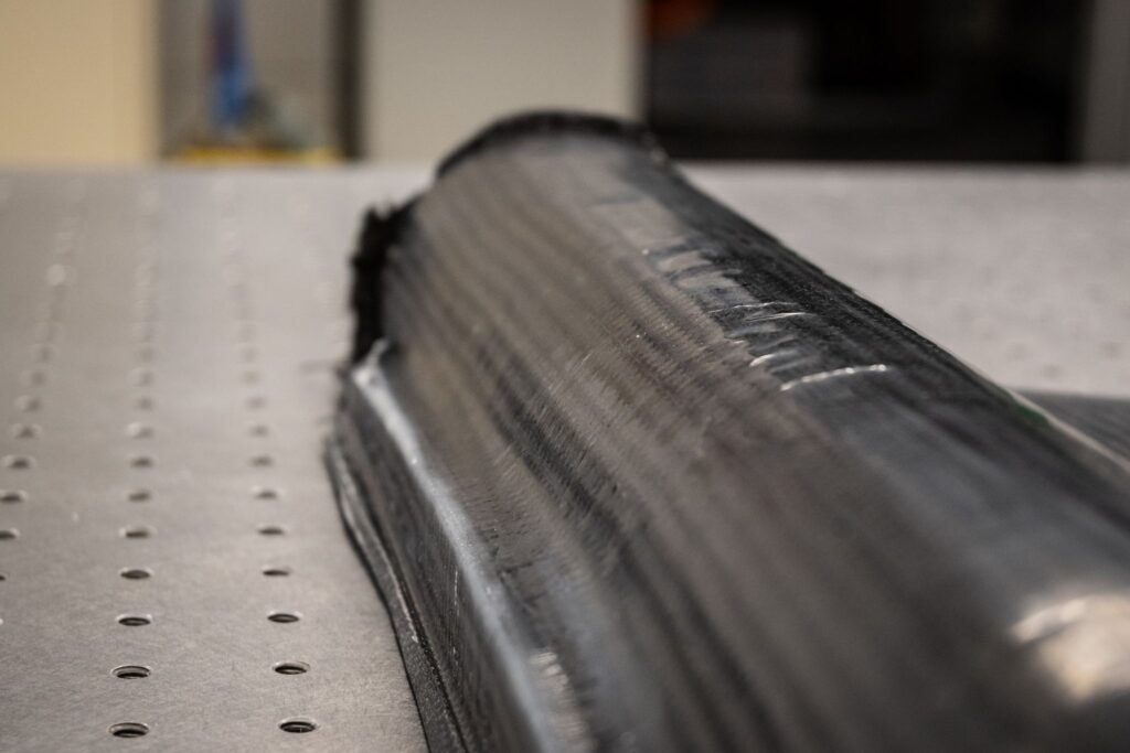
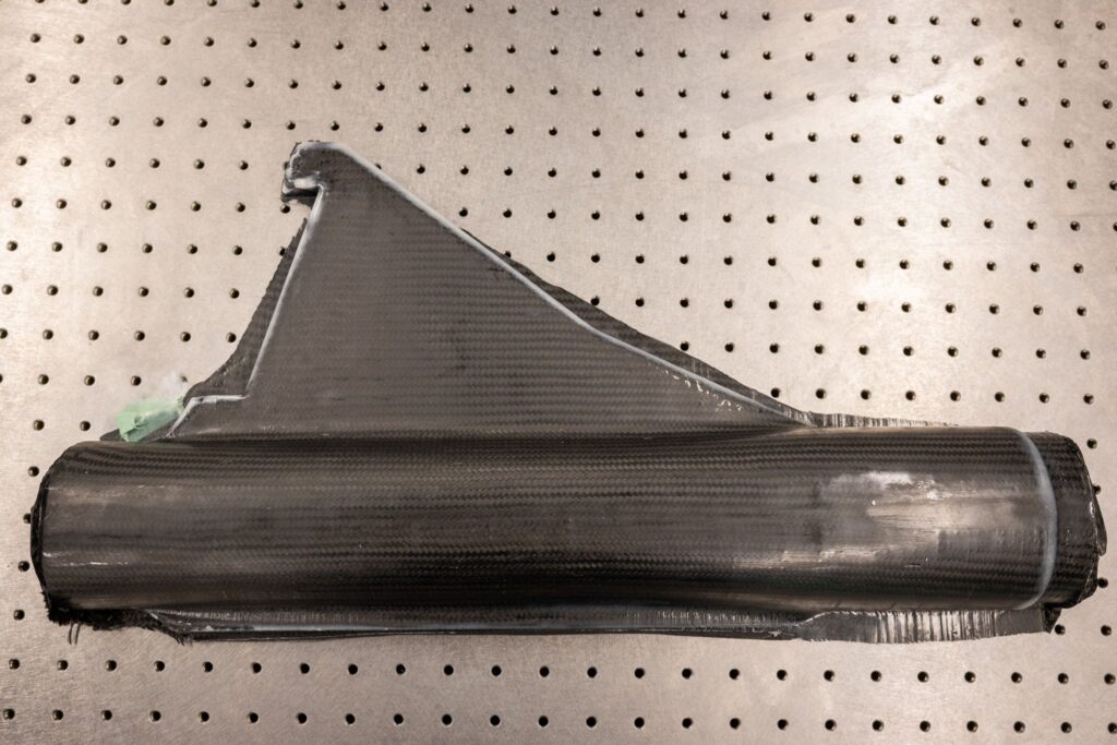
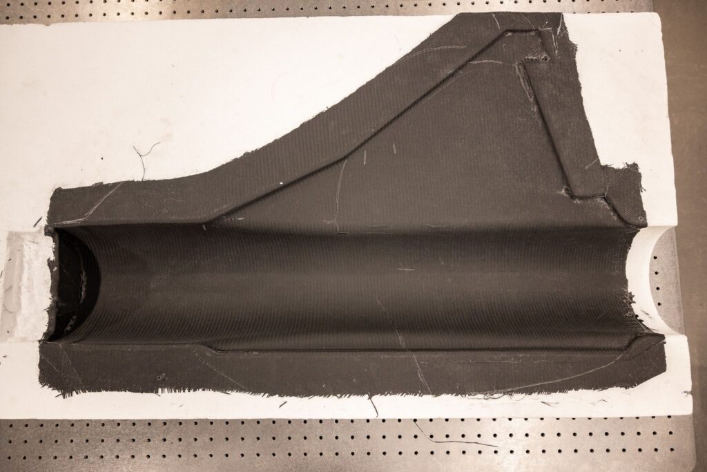
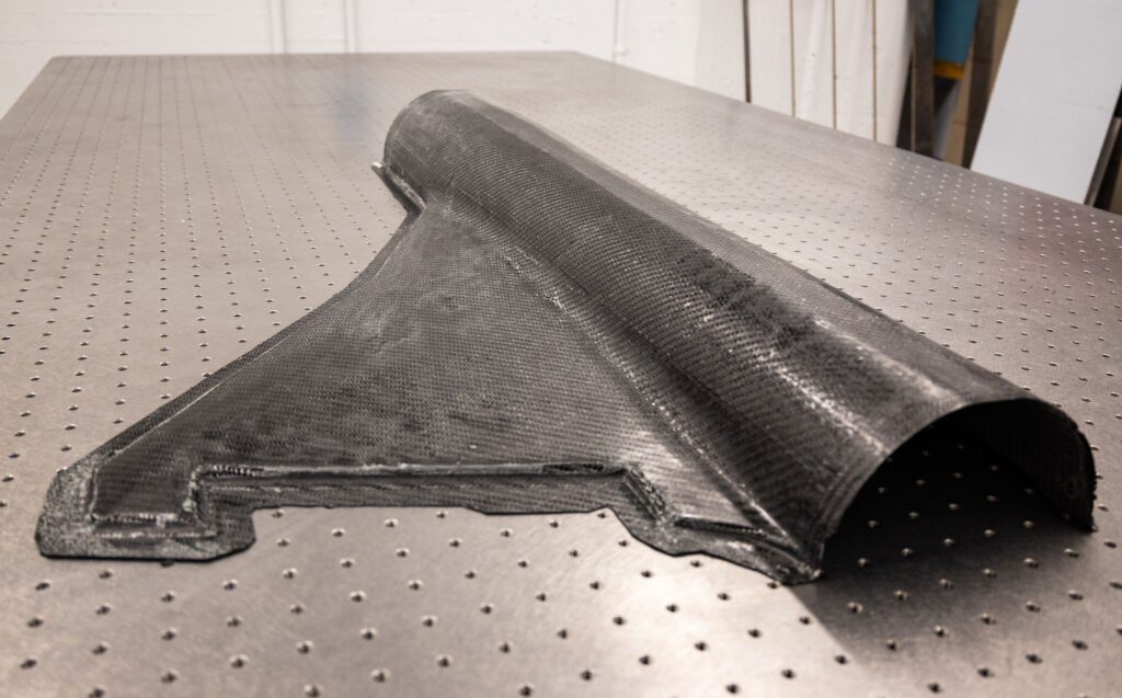
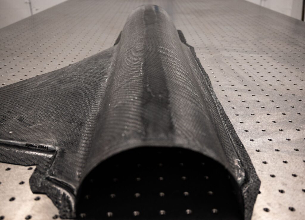
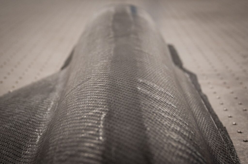
Carbon Fiber Materials and Manufacturing Method
The carbon fiber laminate was designed such that it closely resembled the quasi-isotropic design, where strength and stiffness are equal in all directions within a plane. A 3k 2×2 twill weave provided appropriate fabric stability, workability, and strength.
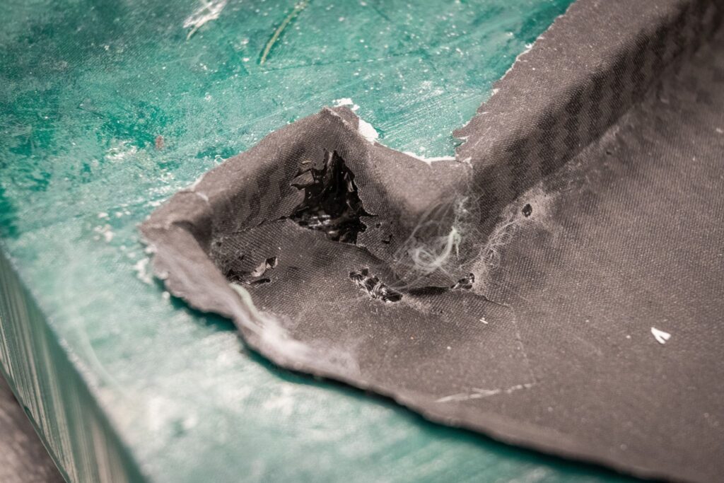
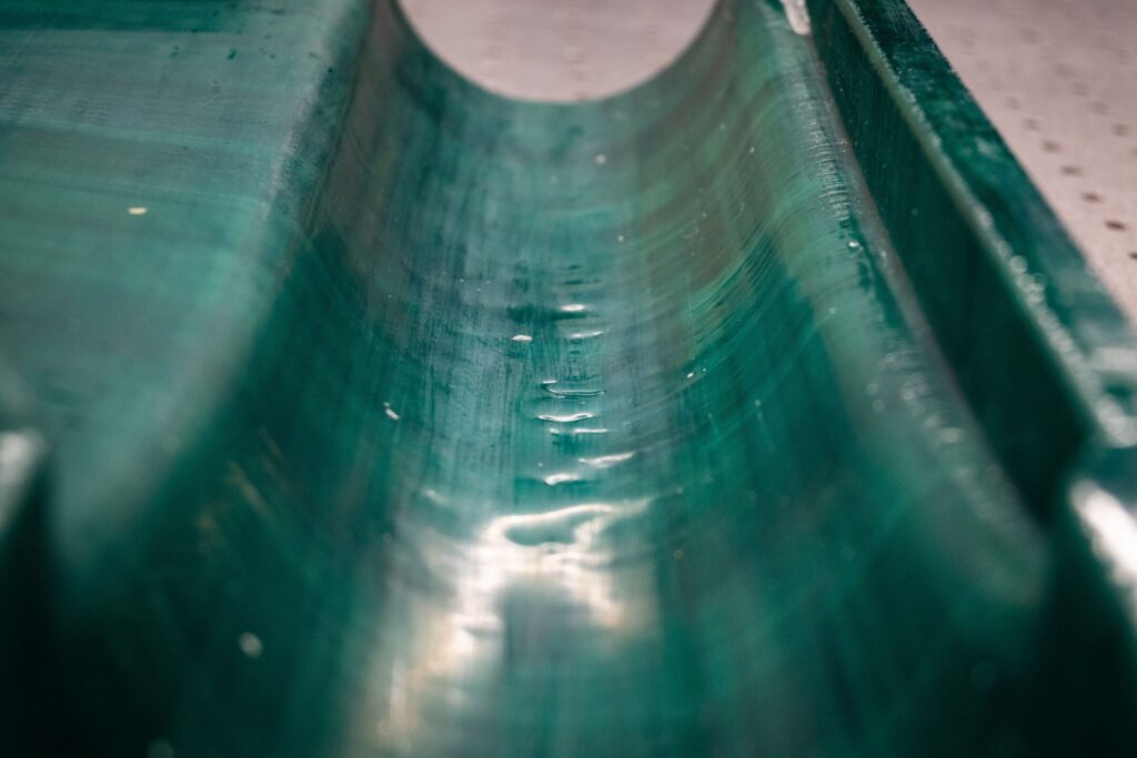
The ¼- and ½-scale molds were stabilized with an epoxy and smoothly sanded, then buffed with five coats of mold release wax. During layup, the carbon fiber was cut to shape, saturated with epoxy in layers, and laid into the mold without affecting the desired weave and ply orientations. A peel ply layer was applied on top, followed by breather cloth to soak up excess resin during the vacuum infusion process. This manufacturing process was based both on industry standards, as well as mentorship from field experts – which helped the team produce an effective design solution.
HOW WE VALIDATED OUR DESIGN SOLUTION
At every stage of the design process, the team use a variety of tools and methods to validate the aircraft performance. Such systems include, ANSYS, ANSYS ACP (Ansys Composite Pre-Post) and SUAVE (open-source computational tool for calculating real world flight profiles with plane geometries).
ANSYS
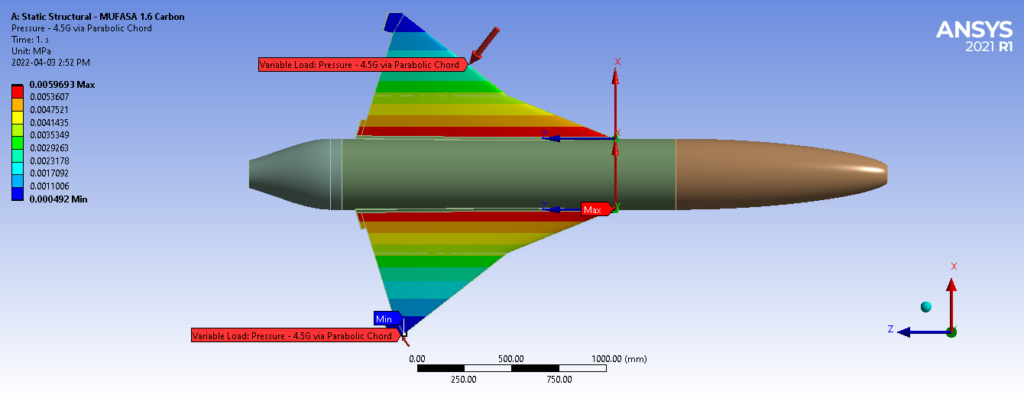
The full-body structure was imported into ANSYS static/structural module and approximated using a tetrahedral element mesh subject to quadratic solutions. Following a literature review and consultation with Atlantis Research Labs engineers, structural performance was verified under the theoretical failure loading scenarios below, and a safety factor of 1.5:
• +4.5/-3 Gs of distributed pressure;
• +4.5/-3 Gs of ramped pressure (via the chord profile); and
• a cantilevered 25.7 kg engine mass acting directly on supports.

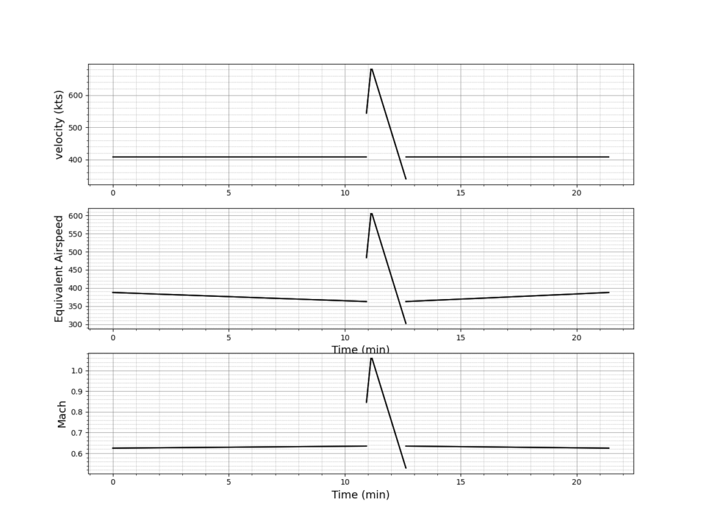
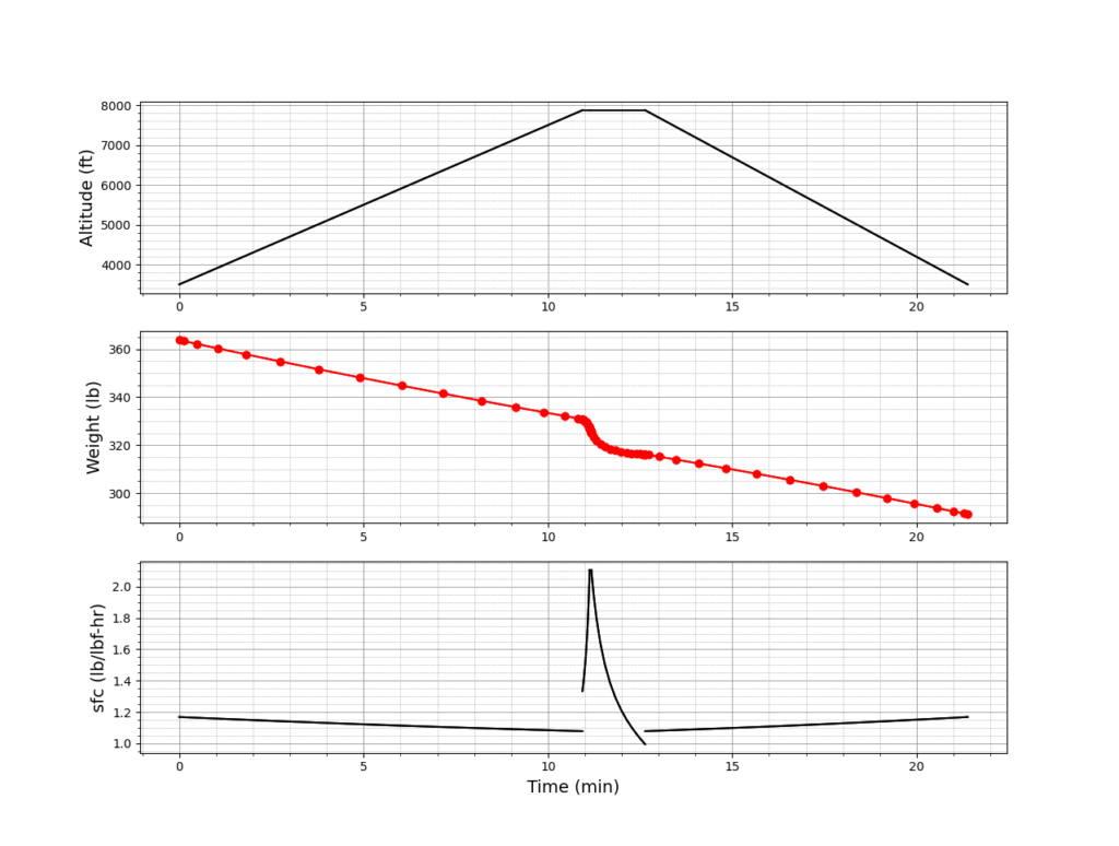
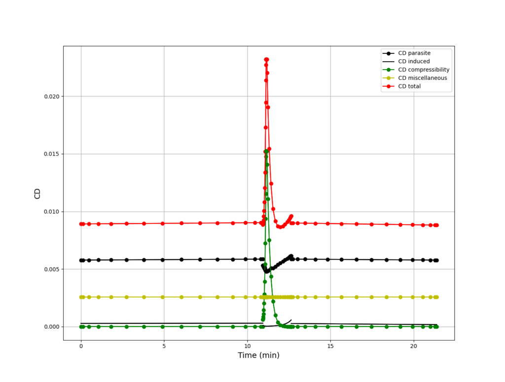
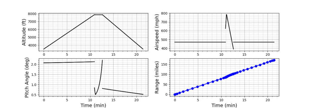
SUAVE
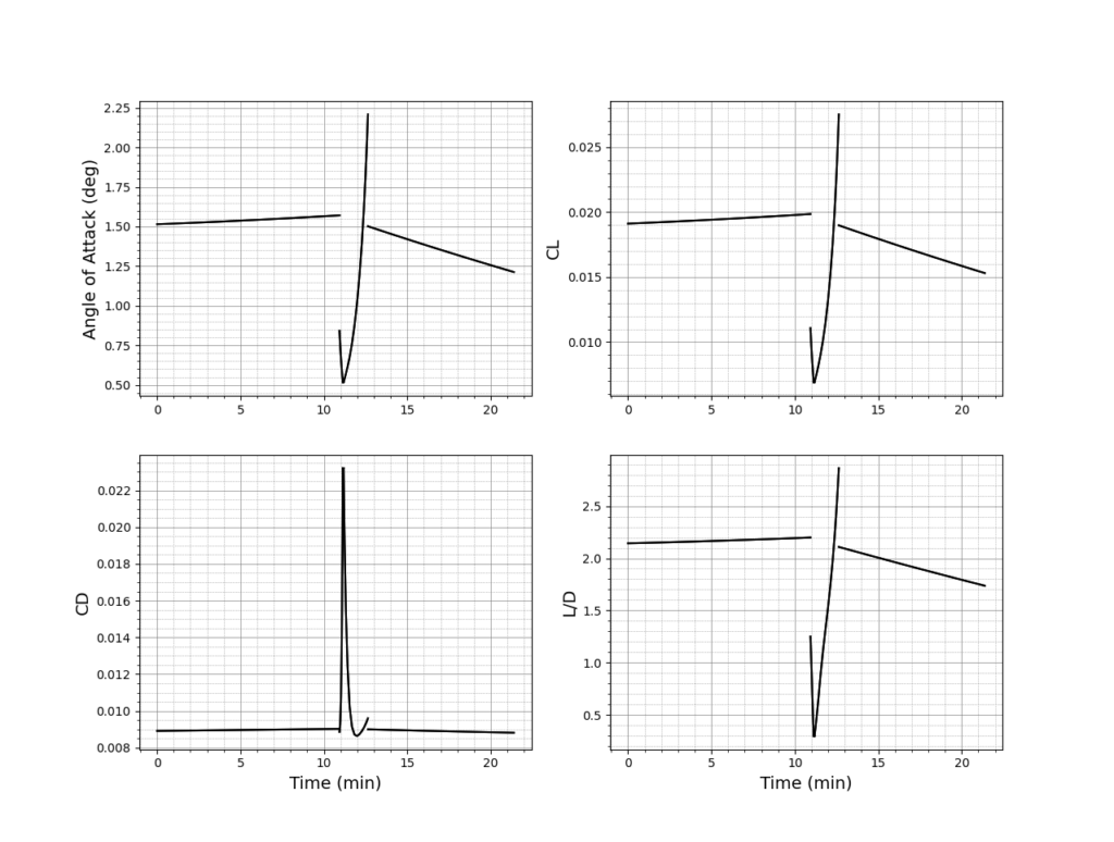
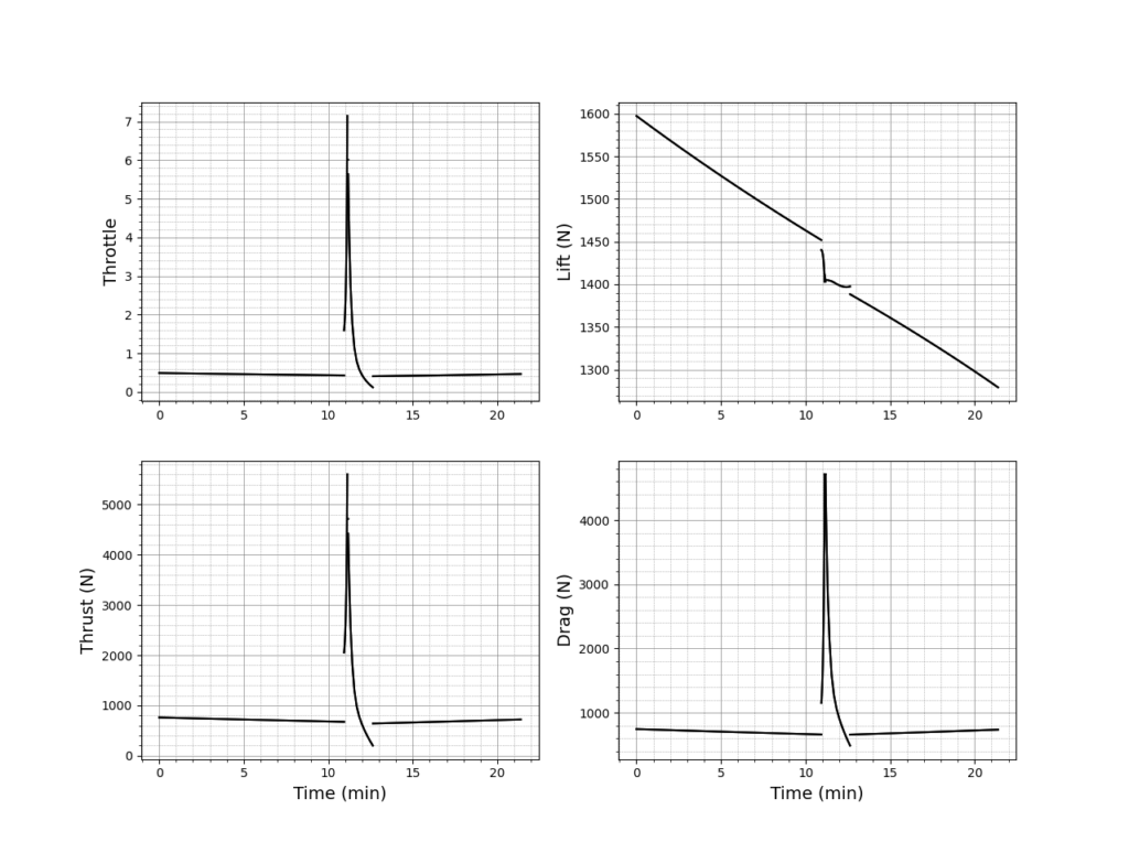
SUAVE python tool is used to validate our changes in design, specifically the weight changes and the geometric profile changes done with computation fluid dynamics (CFD) analysis. The primary reason for this validation is to determine if the engine (AMT Lynx) can produce enough thrust to achieve supersonic flight, as well as determine flight characteristics for our initial calculations, such as stall speeds and optimization for the max coefficient of lift. Our group was able to run the SUAVE system on a zero-fidelity simulation, which is an approximation-based simulation, with step calculations across the airframe and a spline interpolation to determine the full drag or lift profile.
FEASIBILITY OF OUR DESIGN SOLUTION
The project produced a viable composite carbon fiber-epoxy matrix external shell re-design, and successful vacuum infusion layups at partial ¼- and ½-scales, speaking to the feasibility of the design. For high-level material reduction and re-design of the aluminum structural components was also completed to support the inclusion of a supersonic-capable engine, more fuel and landing gear while reducing overall scaled weight by over 55 kg. Calculations and significant design for landing gear were also undertaken to explore fit. Finally, consideration was given to the control systems, which was primarily completed in previous versions of the model.
Partners and mentors
We would like to express our gratitude to the Schulich School of Engineering and the ENME 501/ENME 502 course coordinators and teaching assistants. In particular, we would like to thank Dr. Egberts and Thomas Mathias for their support, and constant feedback.
We would also like to thank the Aerospace and Compressible Flow Research Group at the University of Calgary (AERO-CORE), particularly, our project sponsor Dr. Craig Johansen, as well as Mr. Shaun Gair, Mr. Sebastian Leblic, Mr. Nick Elderfield, and Mr. Jeff Edwards. In addition, we would like to thank the Atlantis Research Labs (ARL), particularly, Mr. Anno Roobol, Mr. Troy Messinger, and Mr. Declan Quinn for their valuable inputs and technical experience.
Finally, we would like to thank Mr. Bob White at Innovative Wings for his mentorship and guidance on the manufacturing of the UAV.
Our photo gallery
References
- Johansen, C. (2021, September 12). Project 23 – Dr. Johansen – SUPERSONIC UAV. University of Calgary D2L – ENME 501 B01 (Fall 2021) Mechanical Engineering Capstone Design Project 1. Retrieved Dec 9, 2021, from https://d2l.ucalgary.ca/d2l/le/content/405607/viewContent/4828438/View
- Gu, S., & Olivier, H. (2020). Capabilities and limitations of existing hypersonic facilities. Progress in Aerospace Sciences, 113, 100607. https://doi.org/10.1016/j.paerosci.2020.100607
- Chanetz, B., & Chpoun, A. (2000). Shock Tubes and Tunnels: Facilities, Instrumentation and Techniques. In Handbook of Shockwaves (Vol. 1, pp. 652–653). Chapter, Elsevier Science and Technology.
- Advisory Group for Aerospace Research & Development (AGARD). (1994). (report). Quality Assessment for Wind Tunnel Testing. Neuilly-sur-Seine, France: NATO.
- Nishi, A., Miyagi, H., & Higuchi, K. (1993). A Computer-Controlled Wind Tunnel. Journal of Wind Engineering and Industrial Aerodynamics, 46, 837–846.
- Hodges, J. (2008, June 25). Wind Tunnel Workers Watch Sadly as 7X10 Disappears. NASA. Retrieved January 4, 2022, from https://www.nasa.gov/centers/langley/news/researchernews/rn_deconstruction.html
- Dalman, B. (2021). Conceptual design methods for small-scale supersonic uncrewed aerial vehicles (MSc. thesis).
