Project Category: Mechanical
Join our presentation
About our project
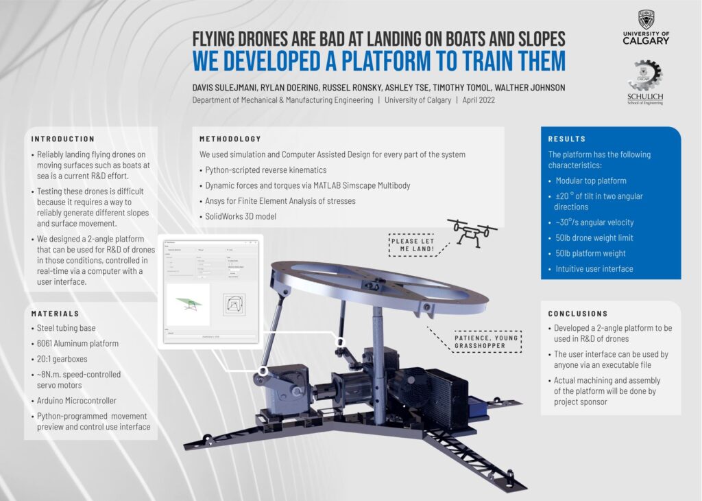
Unmanned Aerial Vehicles (UAV’s) are unpredictable when landing on boats in rough seas or uneven sloped terrain; We developed a solution to test them.
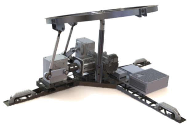
The UAV landing platform is capable of tilting +/- 20 degrees in two perpendicular directions to reliably simulate a variety of landing scenarios on steep sloped terrain. The landing platform also has reliable dynamic capabilities to change the landing surface orientation at angular velocities up to 30 degrees per second for simulating sea-like conditions. The static and dynamic landing scenarios are easily customized via a python programmed user interface that allows the user to preview the orientation and motion based on the user inputs prior to executing the simulation using an on-board Arduino microcontroller. The landing platform is designed with a variety of materials and custom components to ensure adequate strength to withstand the landing forces of UAV’s weighing up to 50lbs but also keep the total landing platform weight below 50lbs for ease of transportation.
UAV technology and R&D has been growing at an accelerating rate since the beginning of the 21st century. The UAV landing platform is the solution to reliably testing and validating UAV landing capabilities in a controlled and accurately simulated environment.
Meet our team members

Tse

Sulejmani

Ronsky

Doering
Tomol

Wennholz Johnson
Details about our design
How our design addresses practical issues
UAV technology and capabilities have been increasing at an unprecedented pace creating a challenge in testing the limits of UAV’s in a controlled environment. For example, it quickly becomes impractical to test the abilities of a UAV to land in rough sea conditions subject to gale force winds given the dangerous environment a UAV pilot would be placed in, the costly failure should the UAV not meet the expected abilities and the logistical challenges associated with getting to the ocean while during a gale force storm wind.
Our design addresses the challenge of testing new UAV technology in rough take-off and landing conditions by first quantifying the wave motion of the sea surface during a gale force wind event and then implementing the conditions in to a scalable UAV landing platform. The extreme conditions resulted in a quantified 2-dimensional wave motion of +/- 20 degrees at the inflection point of the wave and an angular velocity of up to 29 degrees per second.
The UAV landing platform is designed to accommodate UAV’s up to 25kg in weight and that are capable of landing within a 1 square meter area. The UAV landing platform is designed to be less than 50lbs to adhere to the Canadian Occupational Health and Safety Regulations maximum individual manual lifting weight [1]. Additionally, the UAV landing platform is designed to be partially disassembled in less than 5 minutes to reduce the overall size to 40″ x 40″ x 12″ (L x W x H) and have wheels and carry handles so one person is able to safely move the platform from storage to the testing area with ease.
What makes our design innovative
2-DOF approach: Our design is based on a combination of a 2016 University of Calgary capstone team’s UAV landing platform design as well as industry examples of multi-DOF parallel manipulators such as Stuart Platform’s. Specific to simulating sea-like motion, our team decided to neglect vertical translation of the landing platform as a trade-off to increase the robustness and reliability of the platform and reduce the weight to an acceptable limit for transportation by a single individual.
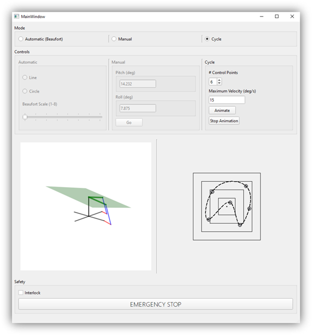
Custom user interface and control system: The graphical user interface designed using python was built from scratch and fully customized to suit the niche use case of our UAV landing platform’s testing parameters and communicate with the multi-mode control system. The platform can be run in three different modes that are called automatic (Beaufort), manual, and cycle mode. Each mode serves a different purpose such as simulating turbulent sea conditions, a specific degree of slope, or a custom path. The ability to do this all from the same interface and with the same landing platform provides the user with endless opportunities to find limitations in their UAV’s landing capabilities and quickly identify areas for improvement.
What makes our design solution effective
Light weight and compact: The design weight and dimensions increases effectiveness of our solution because the user can independently deploy the landing platform and perform testing simulations. Having a rapid and easily available test environment allows for accelerated development in UAV landing capabilities therefore reducing the amount of company resources required to perform testing.
Simple user interface: The user interface is designed to take user inputs and provide immediate feedback via a digital representation of the UAV landing platform. This immediate feedback ensures that the user is satisfied with the simulated motion for testing prior to starting the testing with the actual landing platform. By doing this, time spent on testing landing scenarios is reduced as there is no repeated trial and error attempts required to confirm the desired platform motion.
How we validated our design solution
Kinematic and Static Engineering Analysis
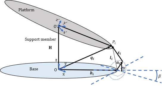
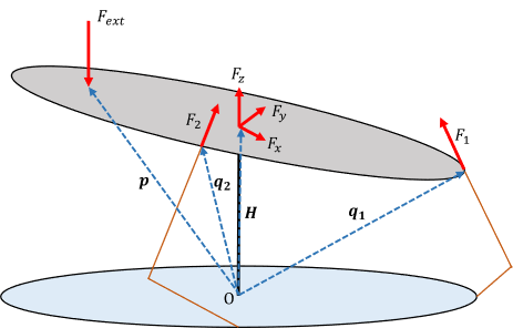
The design team derived kinematic equations via reverse kinematics to calculate servo motor positions based on the platform orientation. Additionally, the static loading on the linkage components and motor were calculated based on certain loading scenarios using force and moment balance equations.
Dynamic Engineering Analysis
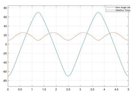
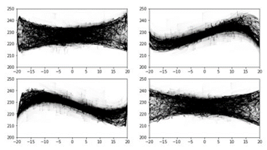
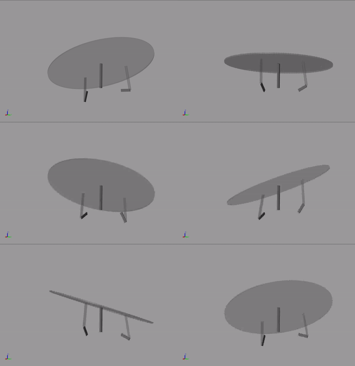
A dynamic engineering analysis was conducted using Simscape Multibody with a simplified UAV landing platform model made up of basic geometries and joints. By inputting position arrays for the servo horns and external UAV landing loads on the platform, we determined the resulting forces on the links and the motor torques required to satisfy the inputs. To account for variability in the landing scenario we measured the maximum forces and torques for 1 million randomly generated load scenarios where inputs such as platform orientation, UAV landing location and UAV landing force were varied to generate worst case scenarios.
Finite Element Analysis
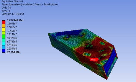
Finite Element Analysis (FEA) was performed on 6 parts that were identified to be stress-critical which resulted in a total of 27 different FEA scenarios performed. During FEA, some components were found to be overdesigned with safety factors as large as 7. This allowed for refinement and optimization of the final design and resulted in no substantially overdesigned components while verifying that all components satisfy a minimum safety factor of 2 when subject to the worst case loading scenario of a 25kg UAV.
Feasibility of our design solution
Machinability: Our design has been reviewed by technicians at the University of Calgary science machine shop and confirmed that all of the custom 3D modelled parts can be manufactured as designed.
Assembly: The landing platform was designed with the use of standard imperial hardware that only requires the use of typical hand tools such as a Philips screw driver and crescent wrench for assembly and disassembly.
Transport: Our design meets the intended weight and dimension criteria so that one individual is easily able to transport and deploy the UAV landing platform.
Operation: The python user interface makes the UAV landing platform simple to interact with and eliminates any requirement for Arduino coding skills as the coding complexities are handled in the back-end code.
Partners and mentors
The team would like to express a special thanks of gratitude to Dr. Alex Ramirez-Serrano for sponsoring this project and providing us this learning opportunity. The success of this project could not have been met without his continuous support, guidance, and feedback throughout the project lifecycle.
We would also like to extend our thank you to our project advisor Dr. Jeff Pieper for his guidance and advice throughout the design phase and Tom Matthias for his feedback and assistance outside the classroom.
Our photo gallery
References
- Government of Canada, “Canadian Occupational Health and Safety Regulations (SOR/86-304),” Minister of Justice, Ottawa, 2021.
