Project Category: Mechanical
About our project
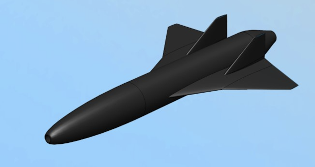
Unmanned Aerial Vehicles (UAVs) are aircrafts without a human operator onboard. UAVs are useful in situations where it would be too expensive or too dangerous to send a human operator. The AERO-CORE team at the University of Calgary is currently conducting research in supersonic UAVs that can fly faster than the speed of sound. An important issue with typical supersonic UAVs is that they cannot fly subsonic, or below the speed of sound. Supersonic UAVs rely on the high speed of flight to get enough air for combustion. The AERO-CORE team is working on a novel intake system that mitigates this issue and would allow a supersonic UAV to stay in flight at subsonic speeds.
To accelerate the early stages of the development and design of the new intake system, a computational fluid dynamics (CFD) simulation would be highly effective, easy to modify and much cheaper than a physical prototype.
The goal of our project is to create a full simulation of a UAV incorporating the new intake system and to provide a working framework to the AERO-CORE team to effectively examine and optimize the design. Our design consists of four main components: the intake, combustor, nozzle, and external aerodynamics.
Join us live!
Zoom Meeting ID: 981 4417 9139
Meet our team members


Tina Ham
Team Lead and Organizer
Shiva Amini
Content Director and Editor


Matthew Halas
Resources Manager, Software SME
Ziad Bayoumy
Communications Lead, CFD SME
Details about our design
WHAT IS OUR DESIGN PROBLEM?
As stated in the introduction, typical supersonic engines have some limitations. They are unable to operate effectively at subsonic speeds, meaning they require an assisted takeoff, and they have a limited range of speeds at which they can fly.
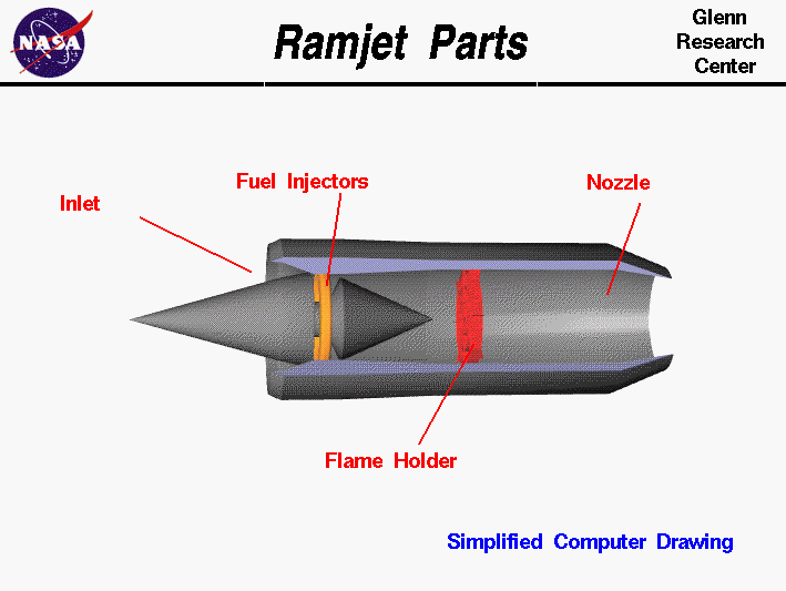
A ram-jet engine relies on retaining the high stagnation pressure of incoming air for combustion to provide sufficient thrust. At subsonic speeds, the engine is not as effective and the thrust it produces is not high enough to overcome the drag on the aircraft.
The novel intake design being researched by the AERO-CORE team at U of C aims to mitigate this issue by increasing the rate of air entering the intake, specifically at subsonic speeds.
Modeling this intake in CFD rather than a physical prototype has a few advantages:
- A simulation is much cheaper than a physical prototype
- Geometrical changes are easier to implement in a simulation
- More in-depth analysis of the flow is available in a simulation
Our group was tasked with developing the numerical framework that can be used to test the novel intake system with CFD. The simulation should be reasonably accurate, and the time taken to run the simulation should be minimized wherever possible. The framework should model the external aerodynamics and internal components of the UAV, which includes the intake, combustor, and nozzle. Developing this framework would give the AERO-CORE team an additional tool in developing the novel intake system.
DESIGN METHODS
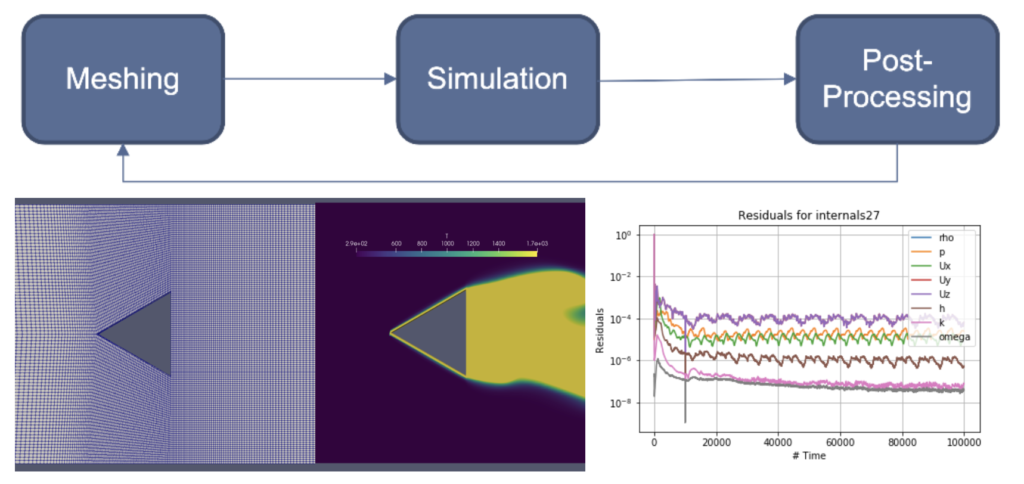
Because of the major role that CFD plays in the project, the group familiarized themselves with the theory and procedures behind CFD simulations. The process began with determining a mathematical model suitable for the simulation which involved making appropriate modifications to the given UAV model, MUFASA (Multipurpose Unmanned Fixed-Wing Advanced Supersonic Aircraft) designed by the Aero-Core Team in 2019.
Meshing (Pre-Processing)
Meshing is arguably the most time consuming and difficult process in CFD. A mesh is a finite number of points throughout the domain (fluid volume that is being simulated). Each point is a set of equations to be solved that represent the fluid flow at that point. It is very important to have a quality mesh in order to have meaningful and accurate results. Our team used ANSA software to clean up the geometry and produce the discretization of each component. Meshing and simulation time were heavily reduced by leveraging the symmetrical components of the model as seen in our video.
Simulation
Our design problem required a CFD solver that must be able to work with compressible and multi-species flow, turbulence, and combustion. These requirements, along with recommendations from AERO-CORE and availability of documentation, guided the team in choosing ReactingPimpleCentralFoam from the open source CFD software, OpenFoam to simulate all components of the UAV. In order to effectively set up a working and robust simulation, considerable research and several test cases were conducted to understand optimal boundary conditions for each module.
Post-Processing
Post-processing CFD data is a vital step in order to accurately derive the right conclusions from the models, present the results, and ensure the best product design. ParaView, is an open-source software used together with OpenFoam to create our visualizations and analyze our data using qualitative and quantitative techniques.
WHAT MAKES OUR DESIGN SOLUTION EFFECTIVE?
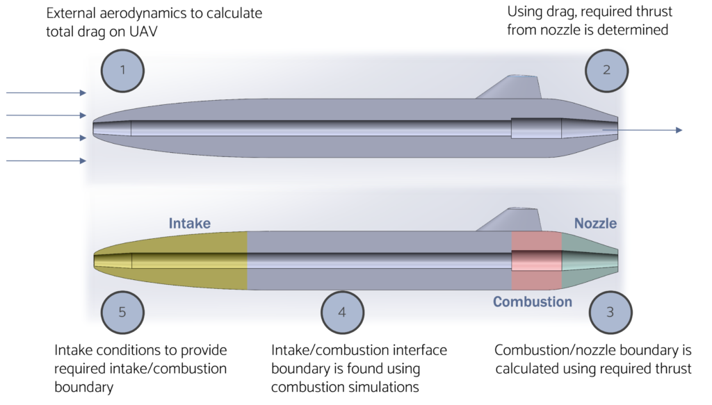
Divide and conquer is a popular method for tackling multi-component project in the world of CFD. In the case of the MUFASA UAV, we split the aircraft into 4 components:
- External Aerodynamics
- Intake
- Combustor
- Nozzle
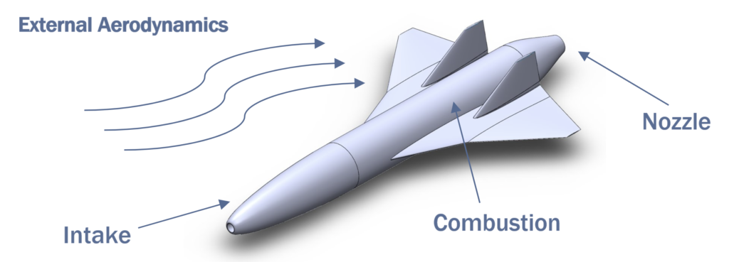
There are multiple reasons for this technique. The main benefits include:
Troubleshooting: Splitting up components allows for more efficient troubleshooting as a smaller and simpler domain makes errors easier to diagnose. This was a favourable choice for the team as members were new to CFD analysis.
Validation: Using common research models (CRM) is a popular validation method. Common research models are usually basic component experiments to be used as a benchmark for testing aircraft designs and models. You may also use a CRM in your simulation structure and if the expected results are outputted, then that CFD method is validated. Since nozzle and combustors are standard components and have available CRM, it was important to split up the UAV to enable the validation of these modules.
HOW IS OUR DESIGN SOLUTION VALIDATED?
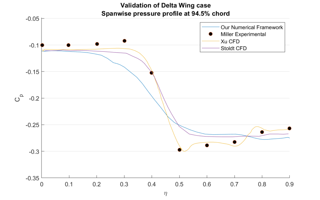
To ensure our CFD simulations accurately represent what would happen in the real world, we must validate the CFD program used. In CFD, validating a simulation means ensuring that the results of the simulation are consistent with real world experimental results. Plenty of validation cases that can be used to validate our simulations are publicly available. The two validation cases used for our project are the Volvo Afterburner, and the Delta Wing.
Volvo Combustion Case
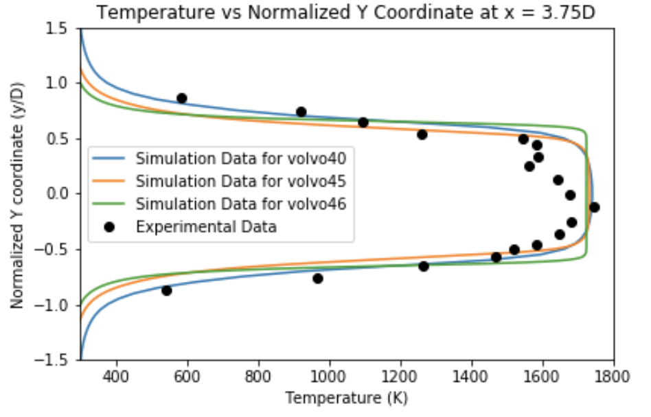
The Volvo Afterburner validation case is used to validate the internal components of the UAV and the CFD solver. The geometry was replicated, simplified, and simulated using OpenFOAM.

The experimental temperature and velocity at various points along the afterburner are compared to the simulation results to validate the solver used. Three iterations of the simulation are compared to experimental data in the images below.

Delta Wing Aerodynamics Case
The Delta Wing validation case was used to validate the solver for an external aerodynamics problem. Additionally, this helped us test the framework’s validity at supersonic conditions.

VERSATILITY
We completed this project with the intention that the AERO-CORE team would be continuing our simulations and further developing it for different test cases. In addition to the progress that we made in creating the simulation of the UAV, we documented all the steps that we took to get where we are. This is done to ensure that any changes that are made to the UAV geometry or solver are easy to implement.
- With the simulation validated using the Delta Wing, the simulation can give fairly accurate results for other aircrafts
- The simulation time is relatively short (<1 week), so various operating conditions can be tested
- In addition to providing the geometry and operating conditions of the combined internals module, we have the geometry and operating conditions of the individual modules
- OpenFoam is a free and open-source software. Additionally, the solvers used in the program can be modified
INTEGRATION
Each individual simulation representing a component of the UAV can be easily integrated to represent the whole UAV by aligning the boundary conditions and operating conditions. Essentially, the output of one component can be set as a boundary condition of the following component, for example the nozzle inlet conditions become outlet conditions of the combustor. Our design approach makes possible the analysis and examination of each essential portion of the aircraft as well as the performance of the full aircraft.
Partners and mentors
We would like to thank Dr. Craig Johansen and Dr. Artem Korobenko for the opportunity to work under their invaluable guidance and sponsorship on this incredibly exciting project.
Special thanks to the graduate students of the AERO-CORE team (Derek Lastiwka, Shaun Gair and Justin Charron) for their continuous support, patience and knowledge as the team undertakes the learning curve of computational fluid dynamics and new software.
Lastly, the team would like to show our sincere appreciation for the learning opportunities provided by the capstone course and feedback provided by Dr. Philip Egberts, Dr. Simon Li and A.J. Ebufegha and for encouraging the team to understand what it takes to execute a design project from start to finish.
Our photo gallery
External Aerodynamics
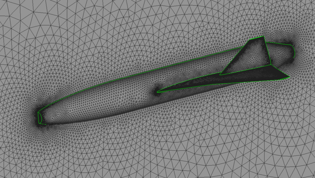
MUFASA UAV Mesh 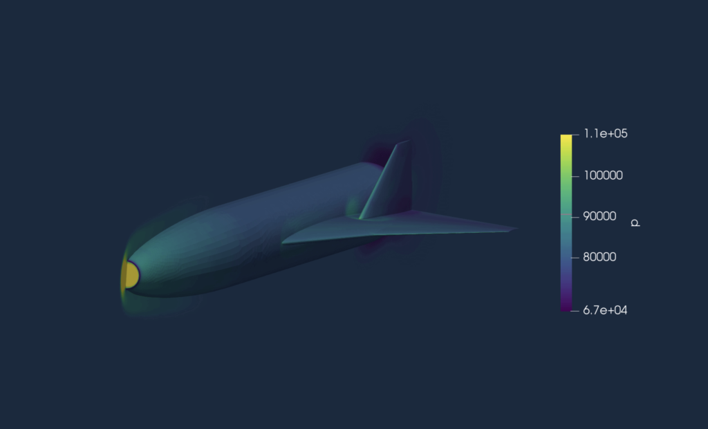
External Aerodynamics Pressure Profile
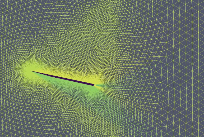
Delta Wing Mesh 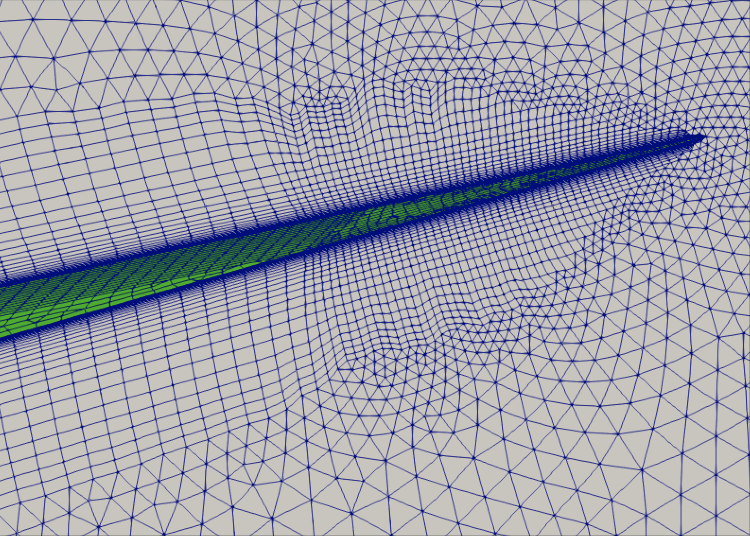
Delta Wing Boundary Layer 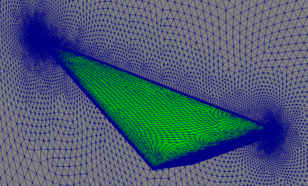
Delta Wing Mesh Rear View
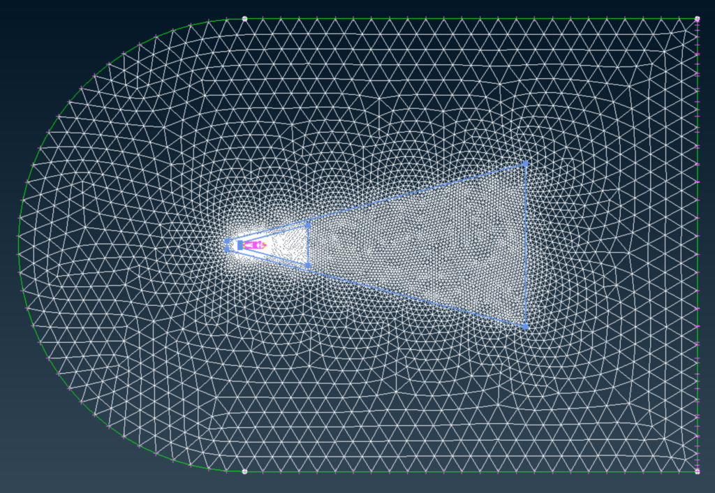
Mesh showing Refinement Zone 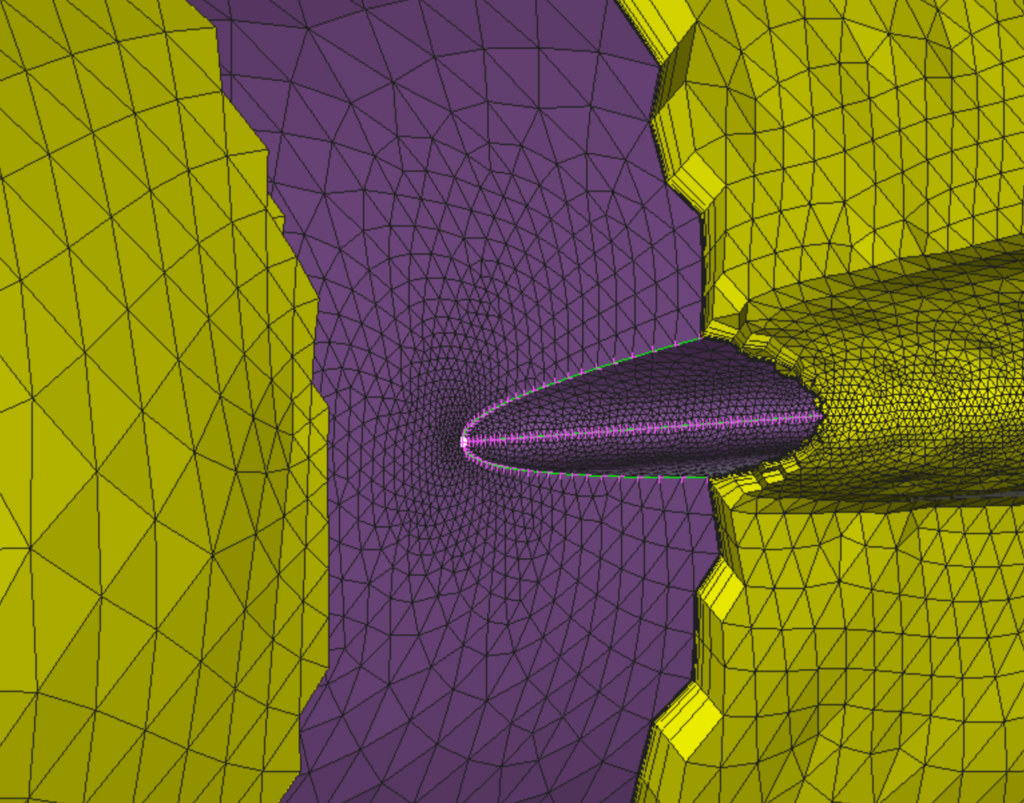
MUFASA UAV Boundary Layer
Internal Components (Intake, Combustor, and Nozzle)
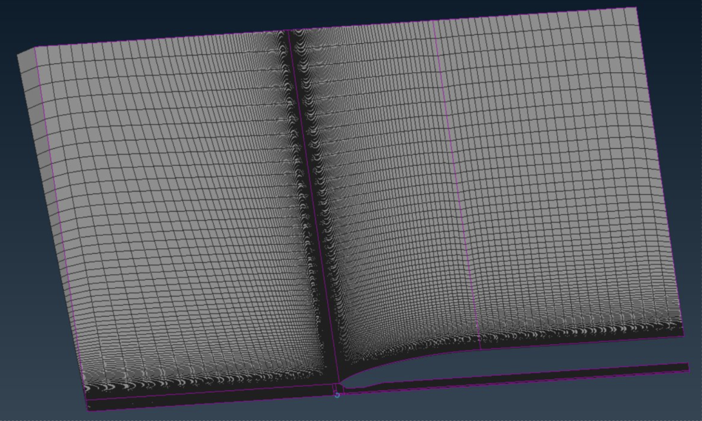
Intake 5-degree Slice Domain 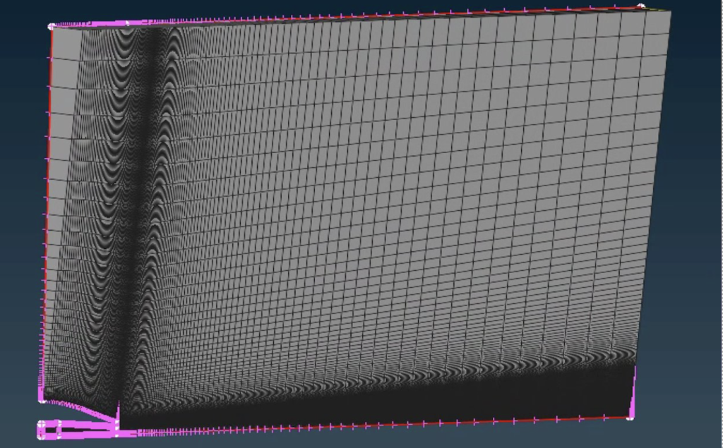
Nozzle 5-degree Slice Domain
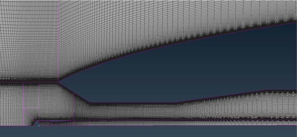
Intake Mesh 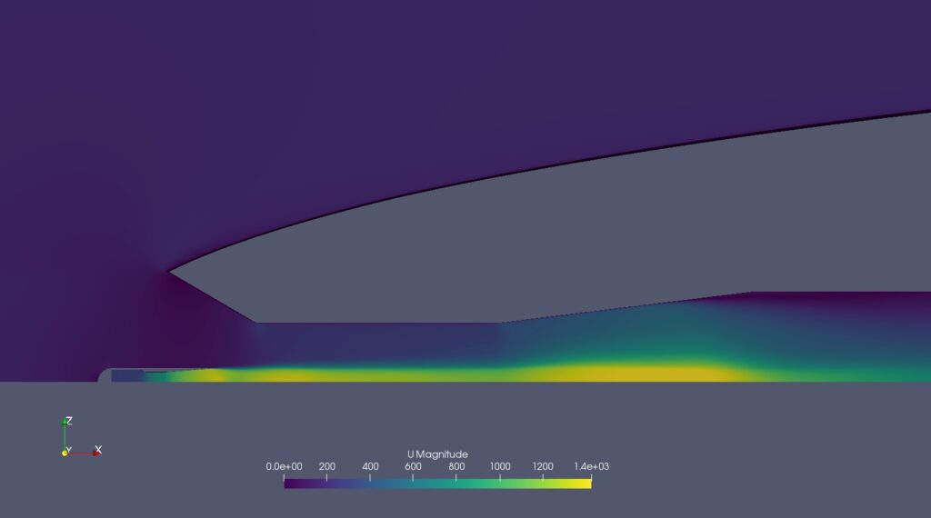
Intake Simulation – Velocity Profile
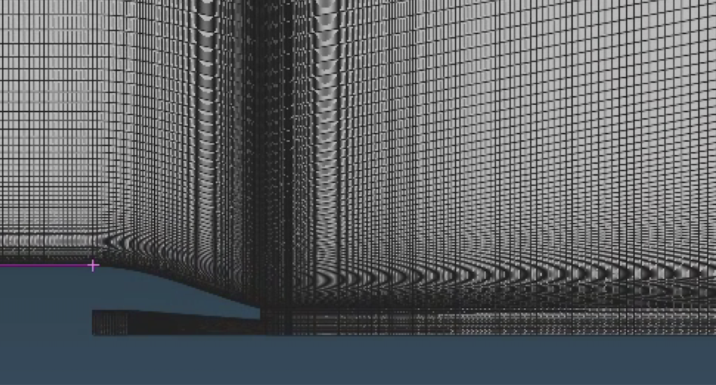
Nozzle Mesh 
Nozzle Simulation – Velocity Profile

Volvo Afterburner Simulation – Temperature Profile

Combined Internals Simulation – Velocity Profile

Intake – Pressure Glyphs Plot 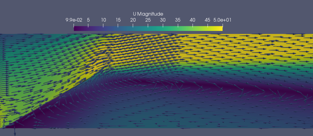
Combustor – Velocity Glyphs Plot
