Project Category: Mechanical
Join Our Presentation
About The Project
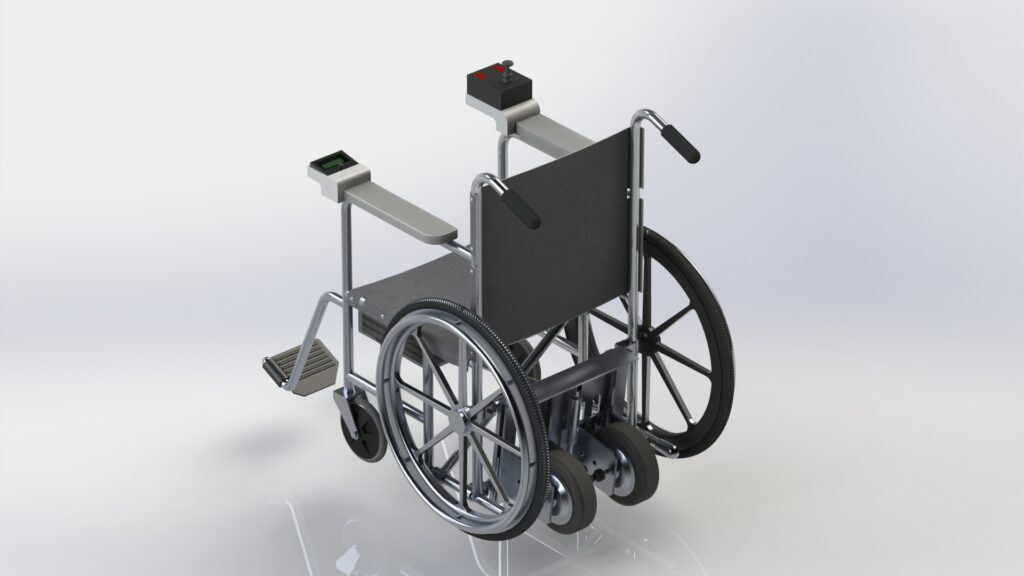
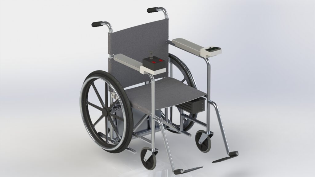
Our design is an electrically powered booster pack for a manual wheelchair. The booster pack is a convenient, affordable alternative to an electric wheelchair for users with moderate mobility challenges. It includes a set of powered wheels mounted on a supporting frame, batteries, and a joystick-based control system. Once installed, the user is able to control their speed and direction completely electronically. The system can also be easily disengaged with a push of a button, allowing the user to switch between manual and electrical operation throughout the day.
When planning our design, we focused on addressing some key challenges faced by manual wheelchair users. Many encounter fatigue and repetitive stress injuries which can limit their independence in day to day life. While electric wheelchairs are a viable alternative, they can be expensive and bulky, making them impractical for many lower income manual wheelchair users. Standard electric wheelchairs cannot be operated manually, reducing the flexibility of choice for those who only occasionally need power support.
The wheelchair booster pack combines the best of both options. It provides electrical drive but also easily allows the user to operate their chair manually. The aim of the kit is to provide a convenient, inexpensive alternative to a full wheelchair upgrade.
Meet the Team

Shannon is in her fifth year of Mechanical Engineering after completing an internship at CNRL. This project arose after discussing the difficulty finding affordable power support wheelchair options with a friend. She enjoyed gaining hands-on experience with fabricating a prototype through this project. Outside of her studies, she enjoys painting and going on outdoor adventures.

Armoghan is a fifth year Mechanical Engineering student with one year of experience working at Suncor Energy on internship as a reliability engineering student. This project allowed him to expand his already strong mechanical design skills using SolidWorks. In his free time he enjoys playing board games with friends, travelling, and trying new types of coffee.

Brandon is in his fifth year of Mechanical Engineering after completing a year long internship at Teck as a mechanical and reliability engineering student. He was able to expand his electrical simulation and SolidWorks skills over the course of this project. Brandon enjoys golfing and playing video games during his spare time.

Smirti is a fourth year Mechanical Engineering student. Through this project she was able to learn more about SolidWorks and finite element analysis. She applied prior knowledge about wheelchairs and accessible design from her time with the Project90 Club. Outside of engineering she’s an avid fan of skating and hiking.

Breanna is in her fourth year of Mechanical Engineering. Through this project she has gained valuable skills in controller logic and programming. She plans to share these skills through teaching programming at Code Ninjas over the summer. Outside of her studies, she is an avid do-it-yourselfer and all around crafty person.
Details about the Design
How Does Our Design Addresses Practical Issues?
Providing Powered Support with Manual Capabilities
Many wheelchair users need occasional additional support but are able to use their wheelchair manually in most situations. The Wheelchair Booster Pack combines the best of both electrical and manual wheelchairs by virtue of its design. The positioning of the pack and the built in lift allow for a user to easily switch between electric drive and manual propulsion without having to remove the device.
Costs Less than a Full Upgrade or Competitive Products
The Wheelchair Booster Pack’s minimalistic design prioritizes function and reduces cost. By maximizing the use of commercially available parts and reducing the amount of customized fabrication required, the team has been able to keep the cost of the device to $875, well below the estimated $1500 for a low end electric wheelchair. This is less expensive than upgrading to a fully electric wheelchair or commercially available boosters.
Long Battery Life with Rechargeable Batteries
To ensure that our design was practical for use, a significant battery life was needed. A device that could only provide assistance for a couple of hours would not be very practical. Additionally, a device that consistently needed its batteries changed would be unappealing and unsustainable. That is why the Wheelchair Booster Pack has been designed with two 36 volt rechargeable battery packs, one for each motor. This provides rechargeability and a battery life of approximately 5 hours under continuous use.
What Makes Our Design Innovative?
It’s not your average push booster
The design does not require the user to still manually push while in electric drive mode. It shifts to a fully functional electric wheelchair when the system is engaged.
It can be entirely removed
The device is designed to be easily attached and removed on a wide variety of wheelchairs. It’s also designed to require very few tools and very little expertise to install.
It is compact
Many comparable booster packs take up extra space in the front or rear of the wheelchair. This can create extra challenges for users trying to navigate tight spaces. Our booster pack is designed to be unobtrusive and to fit within the existing wheelchair frame.
It can be completely customized
The joystick controller can be replaced with any other proportional controller and the code can be modified to suit specific needs. The controller casing, water proofing, and joystick extension can all be aesthetically customized to suit a variety of tastes.
It can be disengaged and tucked out of sight without requiring removal
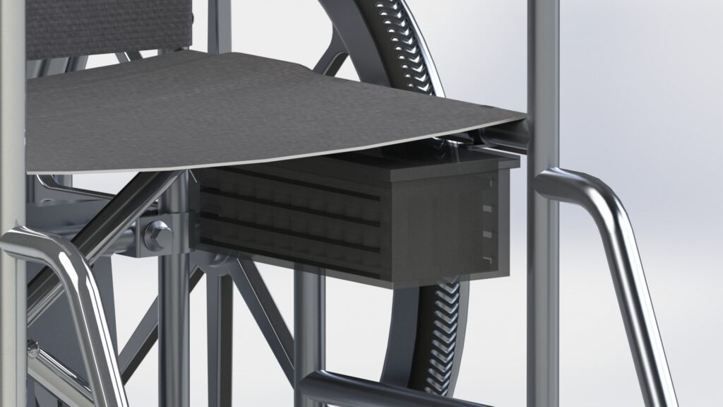
The use of an actuator in the booster pack allows for the powered drive system to be raised up and out of the way when not in use. This allows for full manual operation without having to remove the device.
A completely new set of powered wheels are attached
By adding a new set of wheels under the user’s seat, the need to remove or alter any existing piece of the chair is removed. This also ensures that the push wheels remain operational for manual use; there are no motors or complicated drive systems attached to them.
Affordability
By using mostly commercially available standard parts and making sure the design remained simple, the cost of manufacturing can be kept down. Avoiding unnecessary “bells and whistles” or custom components allows for the booster pack to remain financially accessible for more people.
What Makes Our Design Solution Effective?
Supports typical manual wheelchair usage
The booster pack was designed to effectively support a manual wheelchair user in their daily usage.
–10km/hr max speed
–5 hours of continuous battery use
–Comfortably traverse standard accessible ramps (1:12 running slope)
Intuitive Control System Enhances Accessibility
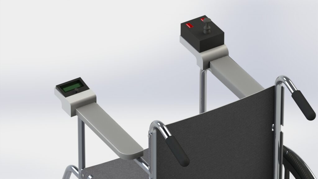
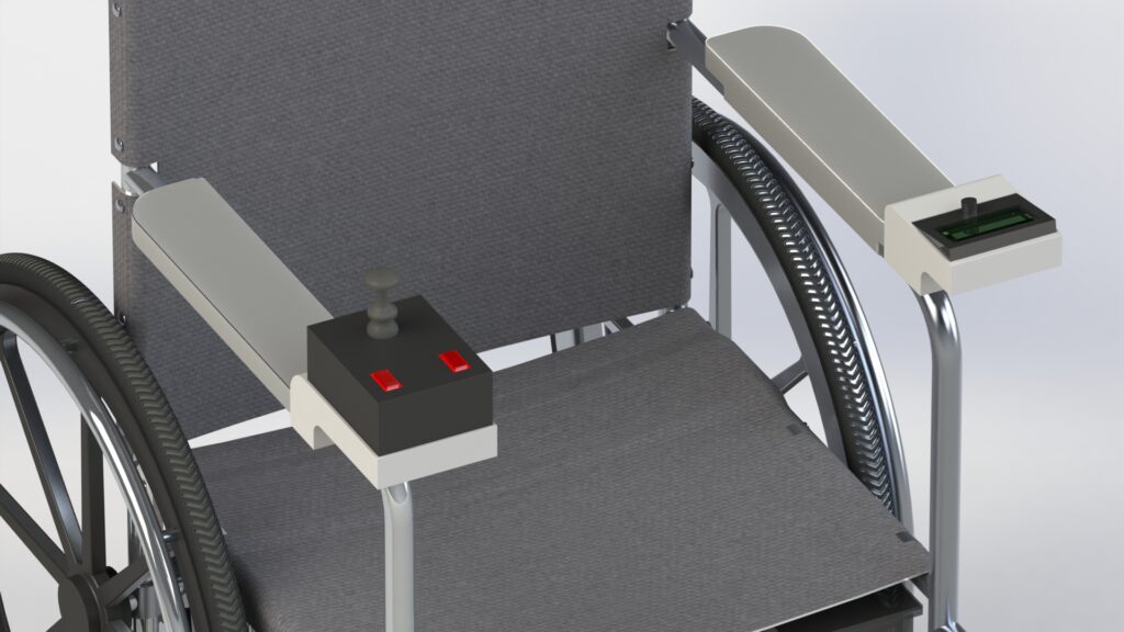
The drive system is operated using a single joystick. This allows for both speed and direction to be controlled simultaneously and comfortably.
–Joystick control is fairly common in day to day life
–One device for full control
–Easy ambidextrous operation
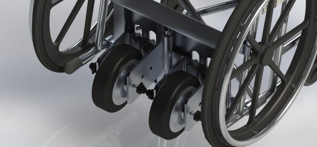
Differential Drive System
Differential drive allows both powered wheels to be operated independently of each other, removing the need for complex mechanical components such as drive shafts and axles.
–Increases ease of repair or replacement
–Reduces failure points
–Allows for a simple and customizable driving program
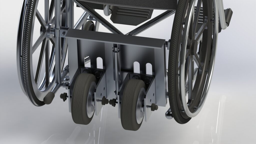
Use of an Actuator for Removal-less Disengagement
The combination of the device placement and the lifting actuator allows for the device to be safely tucked out of the way when not in use.
–Prevents the need to remove the system when manual operation is desired
–Reduces chance of damage from frequent uninstalling and reinstalling
–Allows seamless transitions between electrical and manual operation
Speed Gauge for User Convenience
A rotational sensor consisting of an optical sensor and reflector attached to the push wheel measures and displays true speed readings for the user.
–Provides accurate speed measurements from a physical measurement
–Allows the user to better gauge their speed and stopping time
–Provides immediate feedback for potential motor issues based on speed
Design Validation
A Note Regarding Validation During the Pandemic
To ensure the team’s safety and to adhere to local regulations during the COVID-19 global pandemic, the team was unable to meet in person or access facilities to manufacture a fully functioning version of our design. Instead we thought outside of the box and combined simulations with a few physical prototypes of key systems to ensure the validity of our design.
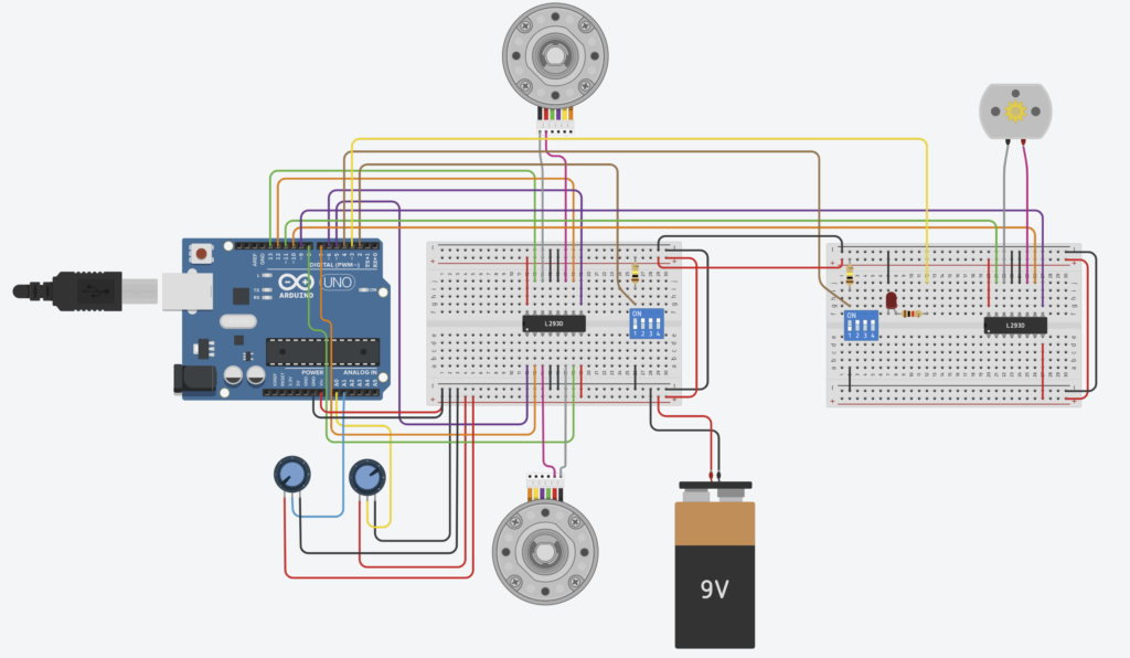
Electronics Simulation
A simulation of the circuitry was prepared in TinkerCAD for the entirety of the system. This allowed for approximating and testing the entire system remotely.

The circuit simulation when activated indicated no problems for the circuit. It also proved that the indicator lights for power status and wheel position activate when expected. The circuit simulation gives us confidence that the circuitry is functional.
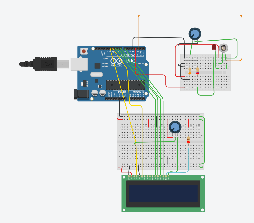
Speed Gauge (Tachometer) Simulation
A simulation of the speed gauge system (tachometer) was created in TinkerCAD to test the concept of the sensor system. This TinkerCAD system, replaces the reflector that would be placed on the push wheel with a blinking LED light for testing purposes.

The simulator compiled properly and presented no signs of functional issues, which has lead the team to believe that the device is capable of accurately measuring the speed of the device.
Physical Prototype
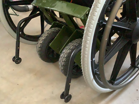
To ensure that the device was dimensioned to fit within the confined space under a wheelchair, and provide sufficient power to propel a wheelchair and user, both a cardboard dimensioning prototype and wooden propulsion prototype were constructed.

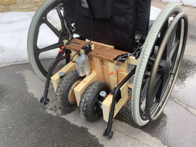
These prototypes allowed us to validate the basic functions of our design. Producing the prototypes and attaching them to the wheelchair validated the feasibility of installation. This device was attached to a wheelchair and tested for fit, engagement, and pushing ability. Based on the test results the device fits comfortably under a wheelchair and works as intended. The user installation process is straight forward and accessible.
Drive Controls Prototype
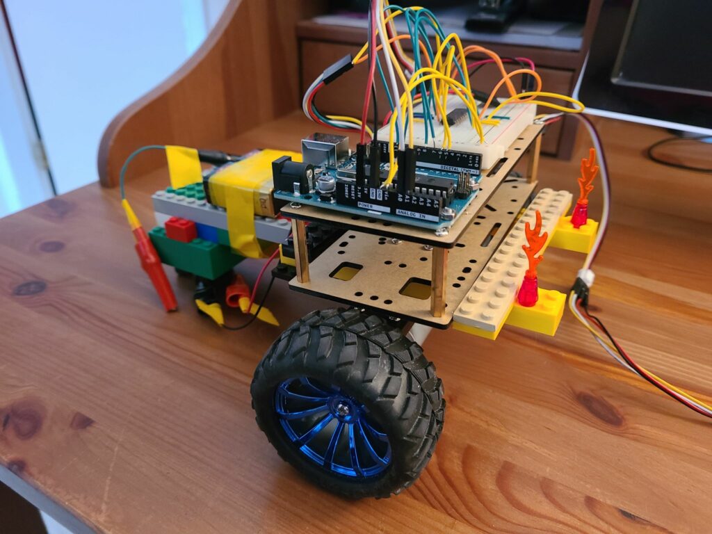
A small scale drive system was constructed using an Arduino Uno, two DC motors, and a joystick. This prototype allowed for the steering logic to be fully tested in a real world environment.

The driving prototype was controlled using the same joystick and Arduino as the design, but the circuit was prototyped using a breadboard which is a plug-and-play method of building circuits. The motors were also smaller and less powerful in this prototype. Despite the prototype component shortcomings, the controller program proved to adequately maneuver the device forwards and backwards, and perform stationary turns. It can be confidently inferred that the steering program, when applied to a fully built device, would function exactly as intended.
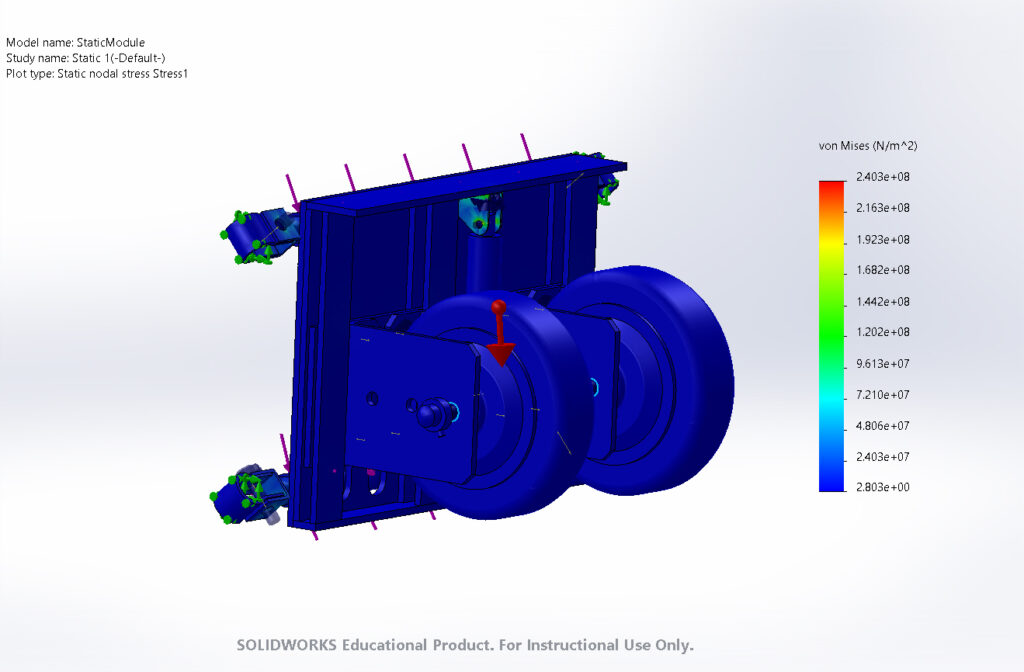
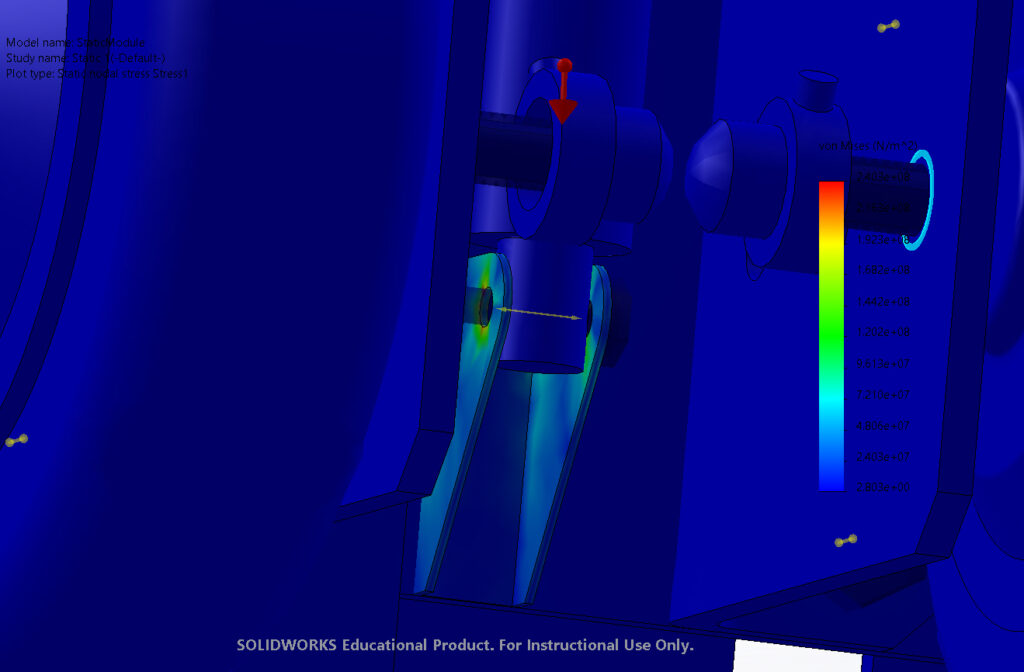
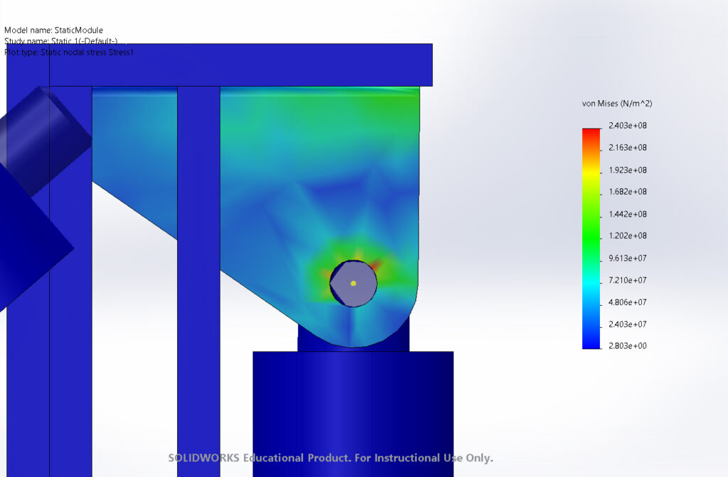
Stress Simulations
Ensuring the device was designed to be structurally sound and safe was a top priority. Therefore multiple strength simulations were performed using digital simulations. SolidWorks was used to test the static stresses of the system.

We selected Aluminum 6061 as the material for the module frame with an approximate yield stress of the system is 270 megapascals. The use of a uniform material prevents galvanic corrosion and Aluminum 6061 has excellent corrosion resistance. Our stress tests which were performed between -20 and 20 degrees Celsius had maximum von Mises stresses at least 20 megapascals below yield. This provides confidence that the frame can withstand stress failure even at locations with high stress concentration.
Budget
The total budget for this design was $875. Our planned budget was less than $1500, the cost of a low end electrical wheelchair, making our design the more affordable option. The largest portion of the budget will go towards the hub motor wheels, a necessary investment to achieve the power support required in a condensed space. We focused on sourcing parts that could easily be replaced by a user, keeping the design accessible.

Acknowledgements
We would like to thank Dr. Philip Egberts and our T.A. Danny Wong for their guidance, insight, and support through this year.
We also wish to express our gratitude to our families for their continued support over these last two semesters.
We would like to acknowledge that we are on Treaty 7 territory, the traditional territories of the Blackfoot Nations, including Siksika, Piikani, and Kainai, the Tsuut’ina Nations, and Stoney Nakoda First Nations. We acknowledge all the many First Nations, Métis, and Inuit whose footsteps have marked these lands for centuries.
Photo Gallery


References
The wheelchair CAD model used in our images was produced by:
MilkNAME8 (2015). “WheelChair” [SolidWorks Model] GrabCAD Community [Online]. Available: https://grabcad.com/library/wheelchai… [Accessed: 05-Dec-2020]
