Project Category: Multidisciplinary

Robotic Autonomous Electro-Mechanical Ocean Navigating Device
Come Meet RAEMOND in Person!
Date: Tuesday, April 5, 2022
Time: 10:00 a.m. to 12:30 p.m. MST
Location: Atrium CNRL Complex (Schulich School of Engineering)
About Our Project
Autonomous Underwater Vehicles (AUVs), or underwater drones, are a heavily utilized technology that perform a wide variety of functions in research, industry, conservation, and the military. However, conventional rigid-hull AUVs have inferior swimming performance when compared to many of the aquatic animals found in our lakes and oceans. Biological swimmers, such as fish and rays, have been shown to achieve greatly improved efficiency, maneuverability, and stealth using their flexible bodies and appendages for propulsion and control.
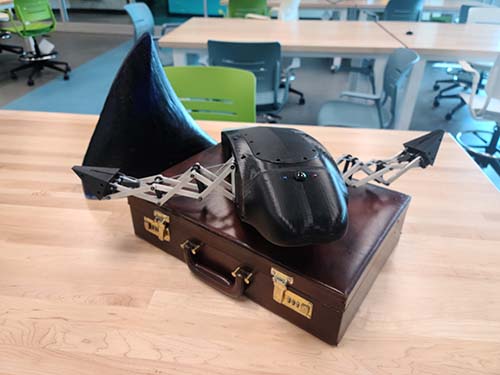
That’s where R.A.E.M.O.N.D. comes in.
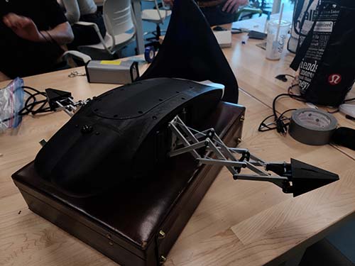
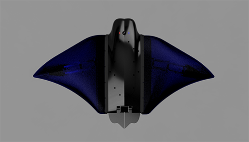
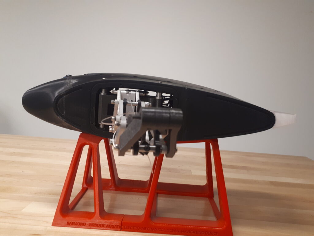
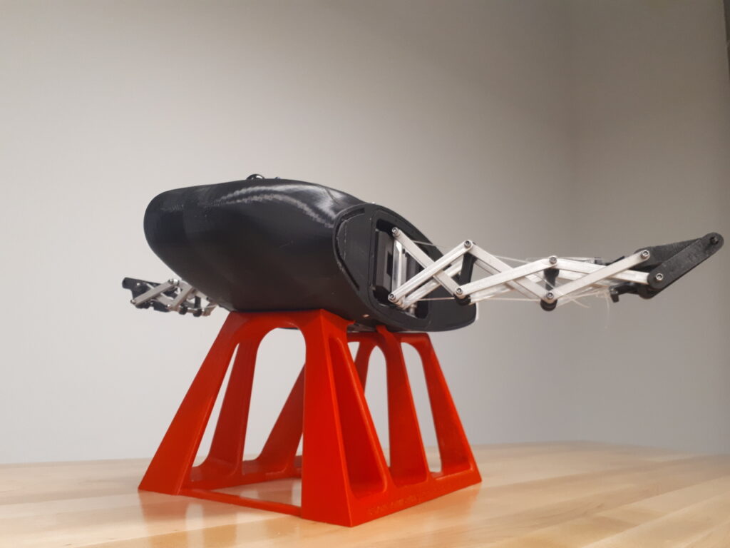
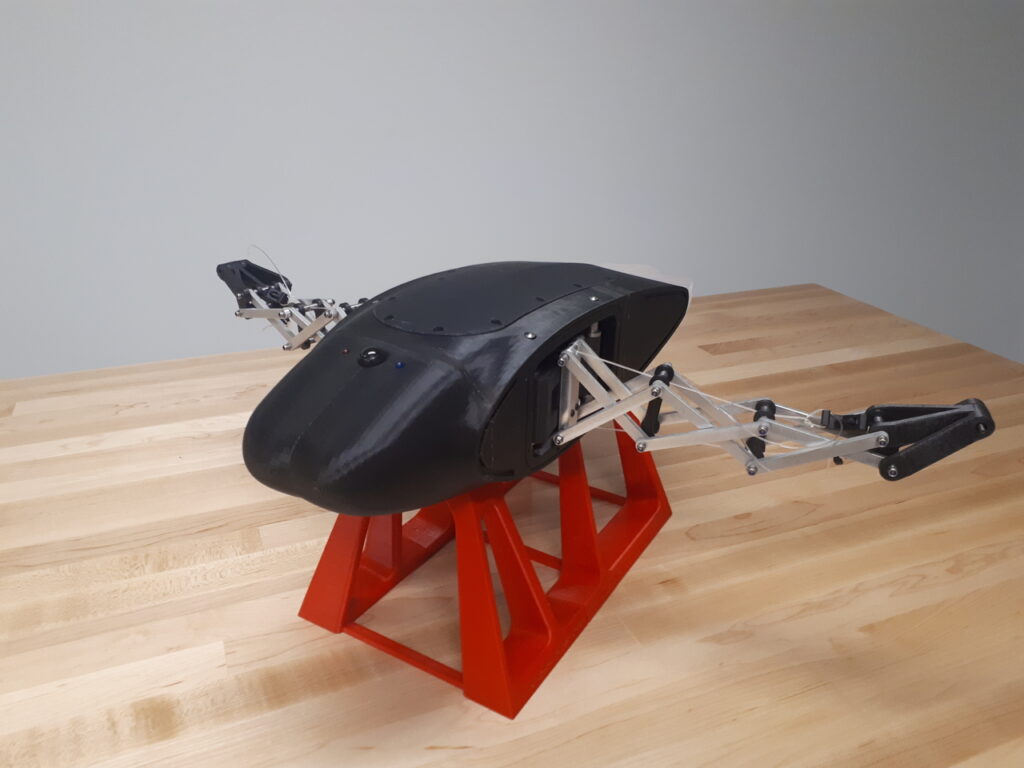
Based on nature’s very own Rhinoptera bonasus, or cownose ray, RAEMOND is a biologically-inspired AUV prototype that makes use of two large flexible pectoral fins to achieve underwater thrust. These wings are actuated up and down using cantilevered tensegrity beams that create a natural flapping motion – much like a manta ray. RAEMOND serves as a practical demonstration of tensegrity technology in robots as well as an inspiration for future biomimetic AUV development.

Main Design Features
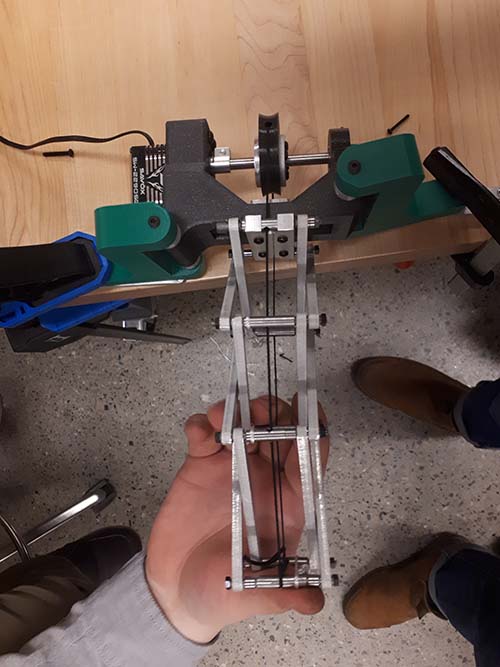
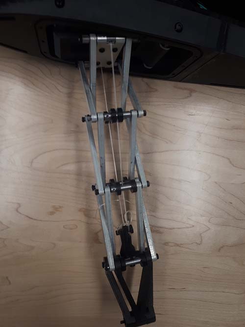
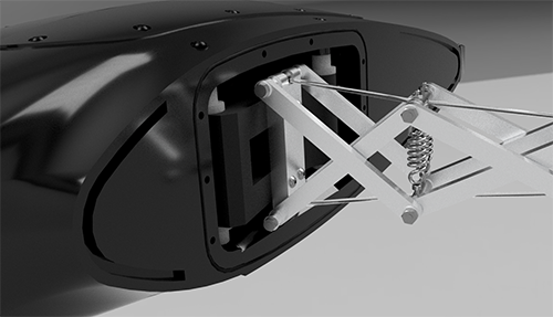
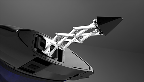
Tensegrity Beam Skeleton
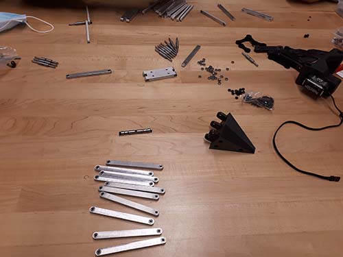
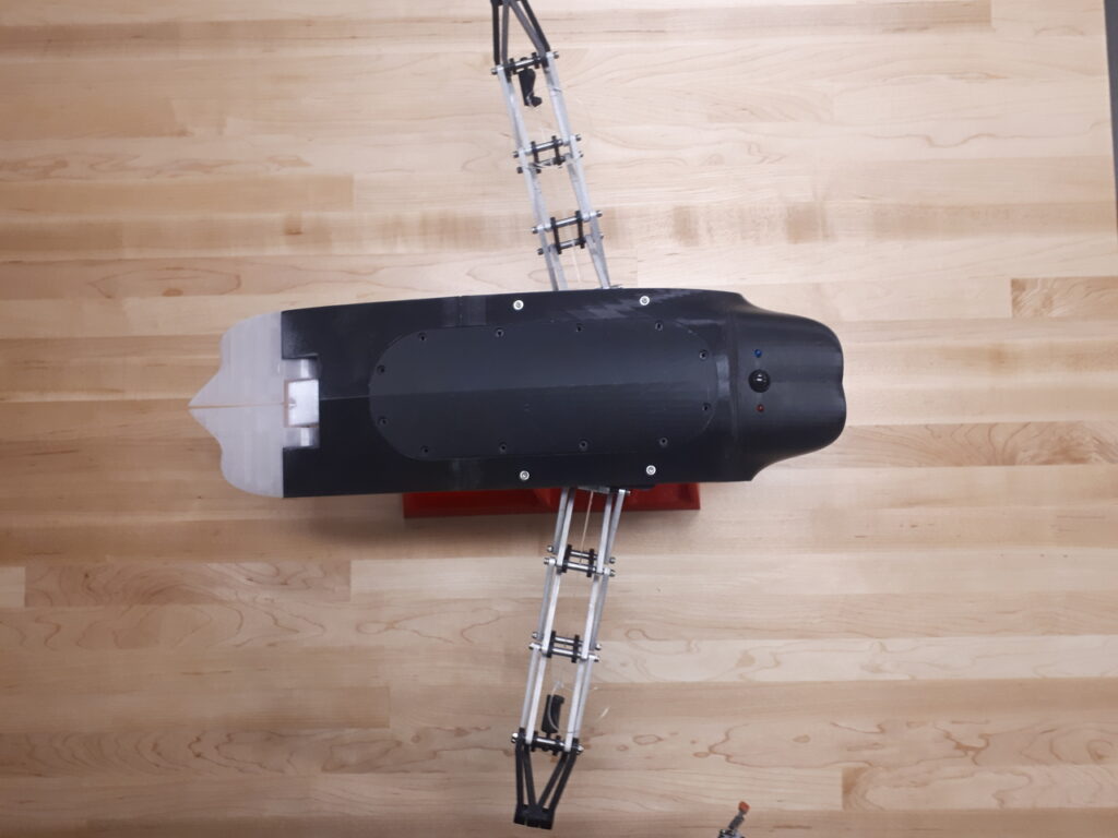
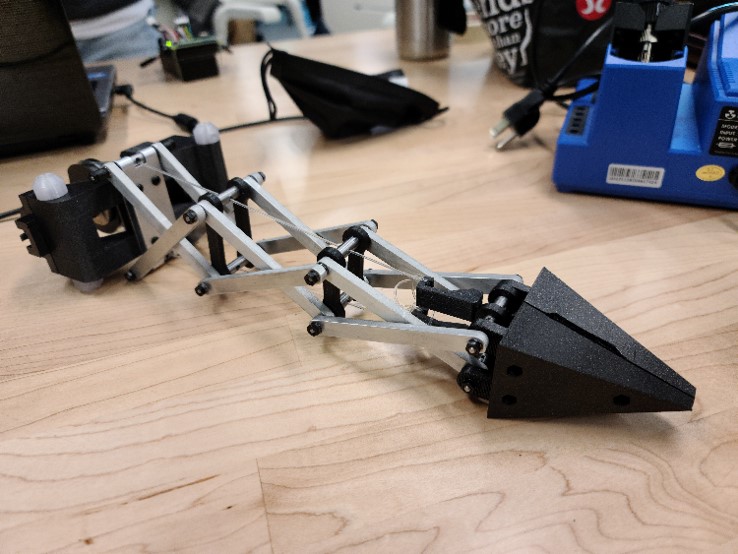
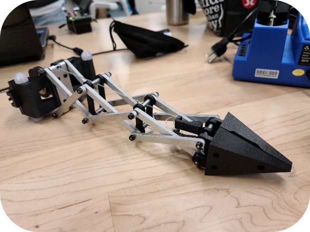
A portmanteau of the words tension and integrity, “tensegrity” refers to a structure held in place by internal tension. Our beams are comprised of a series of rigid metal linkages held upright by two tensioned nylon cables. Waterjet aluminum linkages and turned steel pins are held together by self-locking nuts and over 50 3mm ball bearings to ensure smooth motion of the wings.
These cantilevered tensegrity beams provide structural support for the wings as well as the flexibility to provide a natural “ray-like” actuation when flapping.
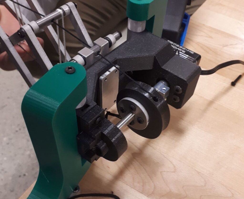
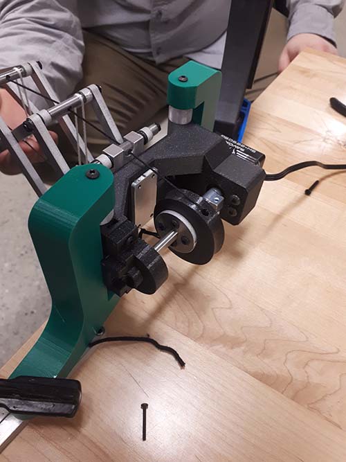
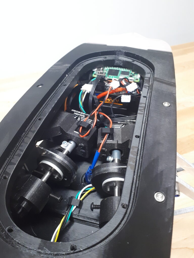
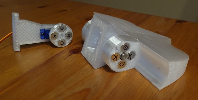
Cam-Cable Actuation
Each tensegrity beam has a tensioned cable running along its top and bottom which is then wrapped around a cam located at the base. This cam is connected via an aluminum shaft to a powerful servo motor capable of actuating the cam back and forth in a sinusoidal motion at speeds up to 2Hz. This causes the cables to pull on opposing sides of the beams in sequence, creating the natural flapping motion.

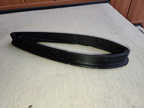
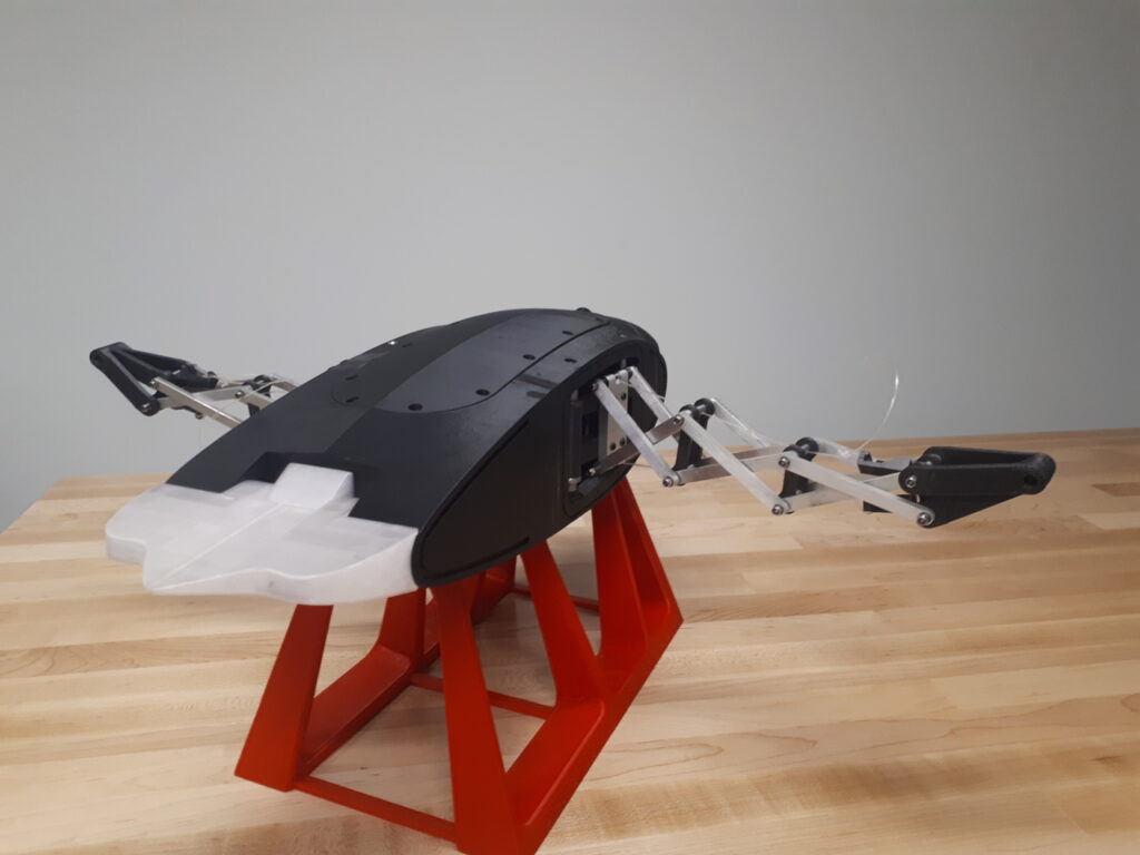
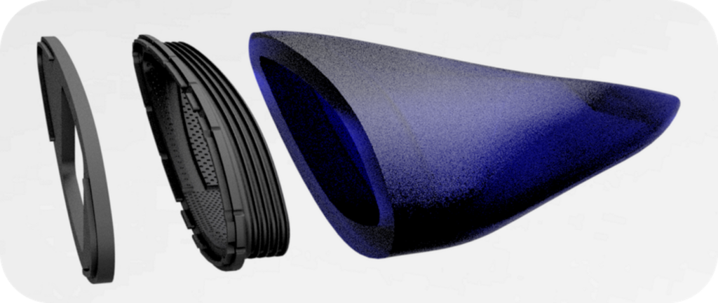
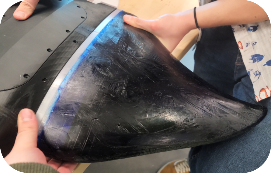
Flexible Polymer Wings
The wing surface is an elastomer sleeve that serves as the “skin”, providing the surface area needed to displace water and create thrust. These wings are designed to mimic the shape of a batoid-ray, and are cast overnight in a custom 3D-printed mold. Each contain a cavity for the tensegrity beam skeleton to slide into, as well as a 3D-printed flange cast directly into the material to provide an attachment point to the body.
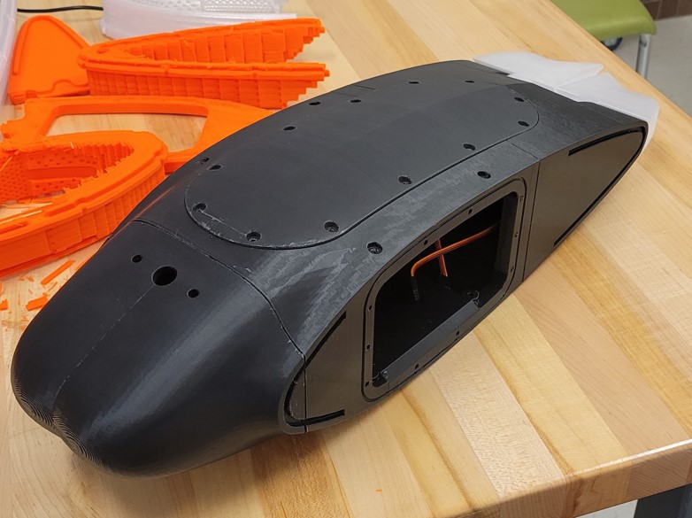
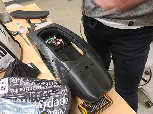
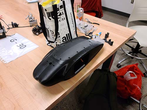
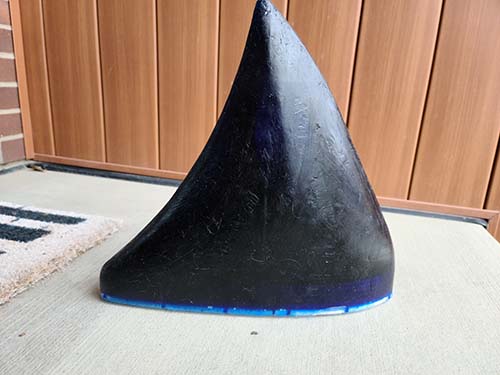
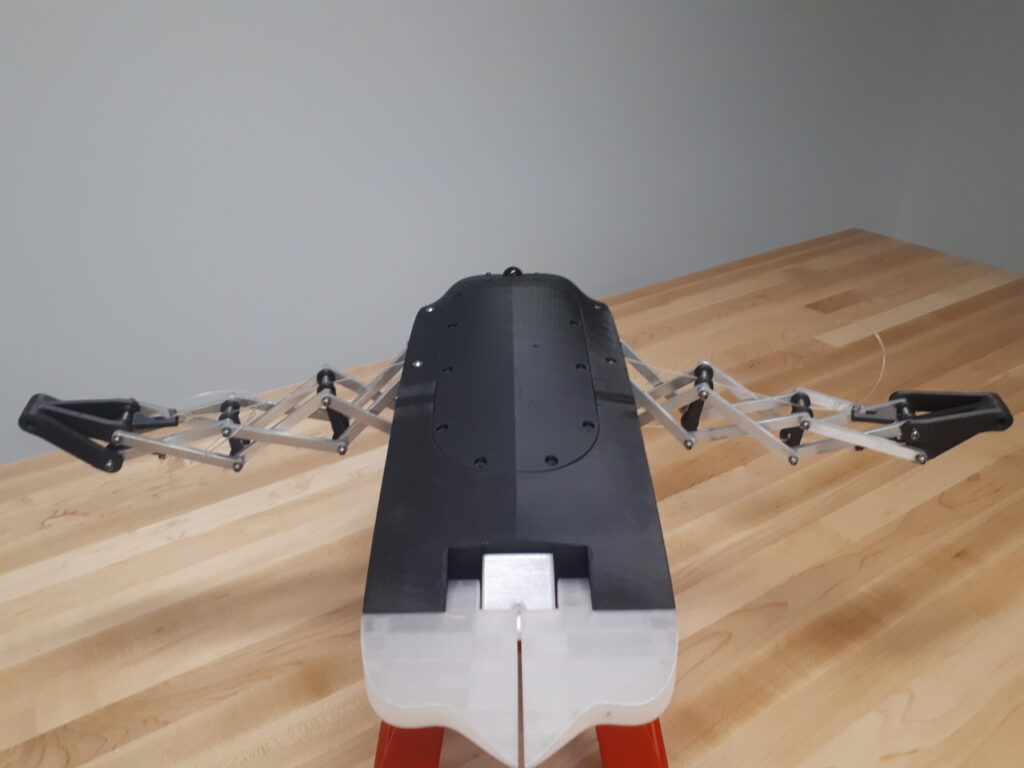
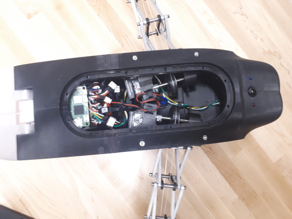
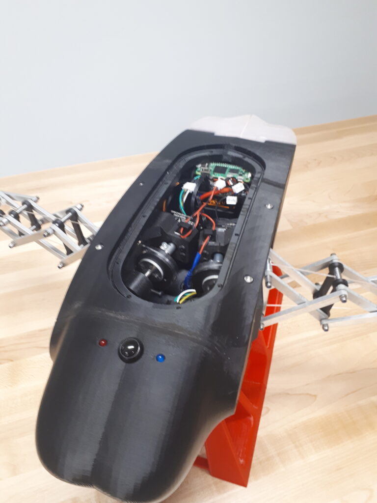
3D-Printed Rigid Hull
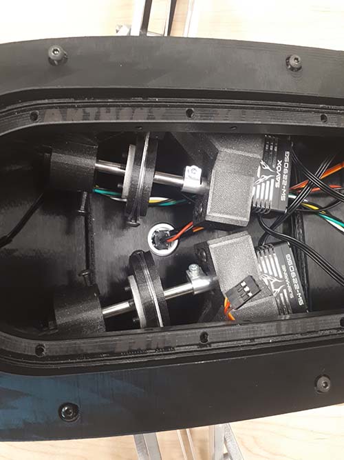
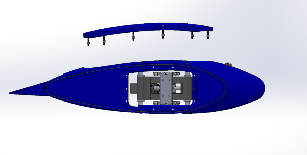
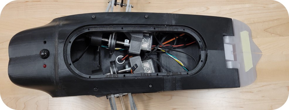
The rigid central hull provides a mounting point for our wings while housing all of our electronics. 3D-printed in sections, it was designed to mimic the cownose ray, which by nature has a drag-reducing hydrodynamic shape. Both the lid and wing-mounting points contain grooves for rubber gaskets that allow the robot to be waterproofed. It also has a sealed removable lid for internal access.
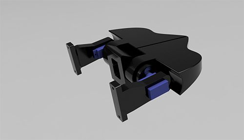
Rear Elevator Flaps
To give RAEMOND additional control and the ability to pitch and roll, two elevator flaps have been incorporated into the rear of the body. These are magnetically coupled through the body to dedicated servo motors. These can be connected to the onboard position sensors to provide feedback control of RAEMOND’s orientation.

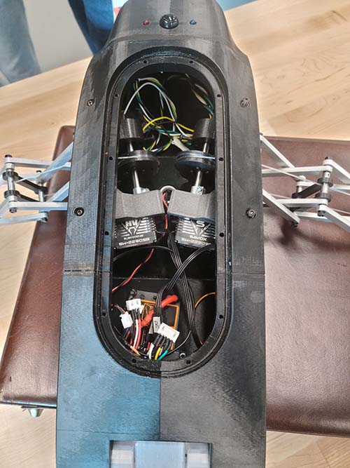
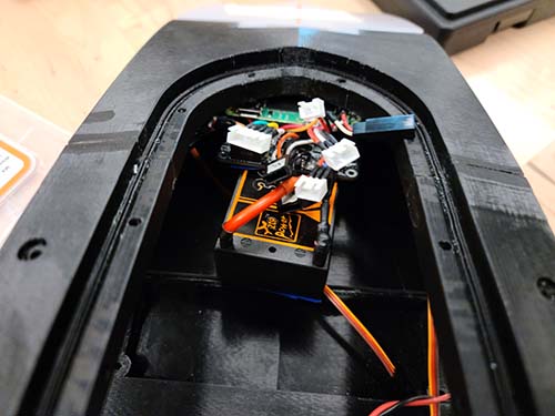
Wireless Electronic Control
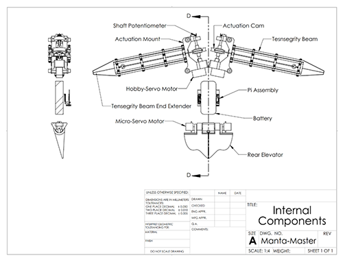
The “brains” of RAEMOND are a Raspberry Pi Zero coupled with a custom-designed printed circuit board. These provide control to both the wing and elevator servo motors while reading in data from sensors such as potentiometers and an inertial measurement unit (IMU). Using the Raspberry Pi and Python 3, the operator can connect to RAEMOND via Bluetooth to send and receive commands with a laptop or another device.
Product Details
Analysis and Design
General Dimensions and Ratios
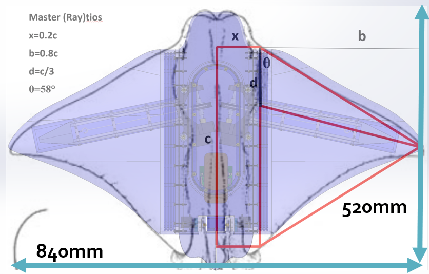
After establishing the general size of the robot based on the project requirements and manufacturing feasibility, the general form of the robot was taken from a cownose ray – which can be found of a similar size in nature. All major relevant internal dimensions, including wing chord length, body width, body length, and thickness were then roughly derived by estimating ratios from images of this ray.
Wing Loading
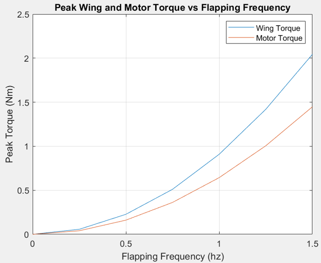
Before designing and selecting a motor/actuation system, it was necessary to obtain an estimate of the fluid forces involved during swimming. To simplify calculations, the wings were modeled as an articulated rigid triangular surface. Then, using analytical formulas the amount of fluid force exerted on each wing was calculated and then translated into a torque on both the wing and motor, respectively. This force estimate was then used to select a motor of an appropriate torque, and suitably strong materials to construct the beam out of.
Thrust Production
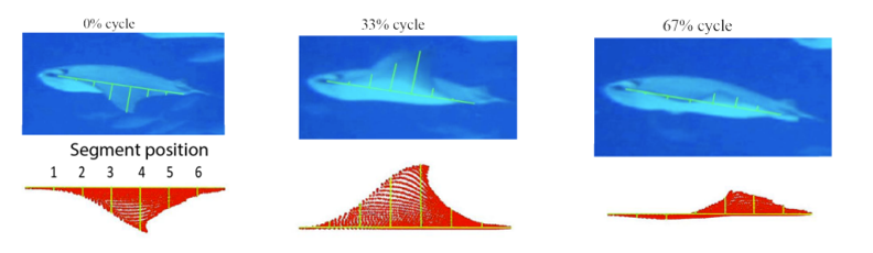
In biological rays, thrust is generated by the “pitching and heaving” motion of an air foil shaped wing, where the air foil angle changes with wing-tip amplitude and displaces water backwards with each stroke. In our robot we will eliminate the need to mechanically pitch the airfoil by making the wing material flexible, causing it to undergo chord-wise deformations with each stroke to achieve the same effect. This is a technique used by real-life rays to improve propulsion capabilities.
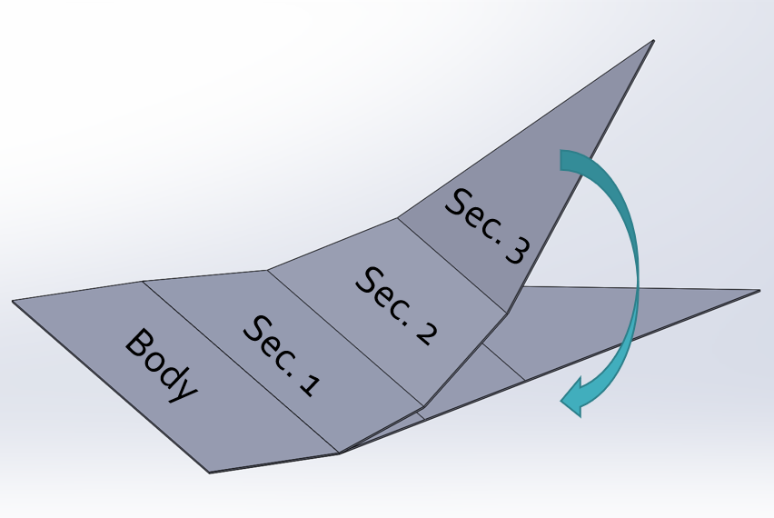
Beam Simulation and Design
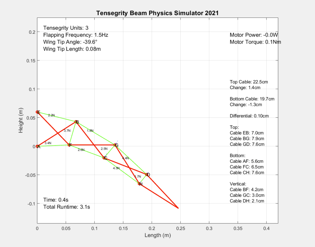
To achieve the desired natural flapping motion of the wings, it was necessary to create a 2D model of the beam and its linkages in order to analyze and understand the underlying kinematics, then choose a suitable geometry. A MATLAB script simulating a 2D model of the beam uses linear algebraic calculations and the ODE45 differential equation solver to obtain kinematics and kinetics of all members in the beam, rigid and elastic. From this, we extract important data, such as expected flapping amplitude, angle, and cable length changes.
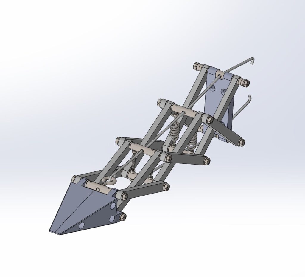
Once a suitable geometry was found using the MATLAB simulation, it was fully 3D modeled in Solidworks. This complete model also includes several additional key features, such variable tensioners for tightening the cable, an aluminum mounting bracket for attachment to the body, and a 3D-printed tip to interface with the wing skin.
Using the fluid forces calculated above, along with the kinematics of the beam, the expected level of stress was calculated for individual members of the beam. In all cases, these produced negligible deformations in the materials used.
Cam Analysis
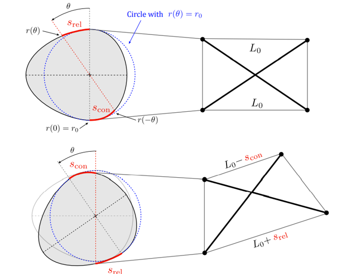
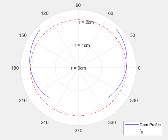
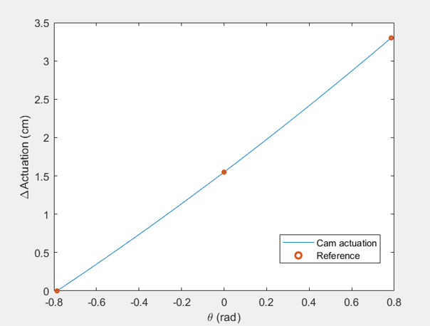
The wings are actuated by contracting and releasing the cables comprising the tensegrity beams, which is done by wrapping them around a cam and rotating it back and forth. However, due to the geometry of the beam, the length of cable being contracted on one side is not equal to the length of cable being released on the other, particularly at large deformations. Thus, we must carefully design an elliptical cam profile to match the changes in cable length that are obtained from the beam simulation above. These lengths were then fed into a MATLAB program which automatically generated a cam profile whose arc lengths most closely matches them during actuation.
Wing Surface Geometry
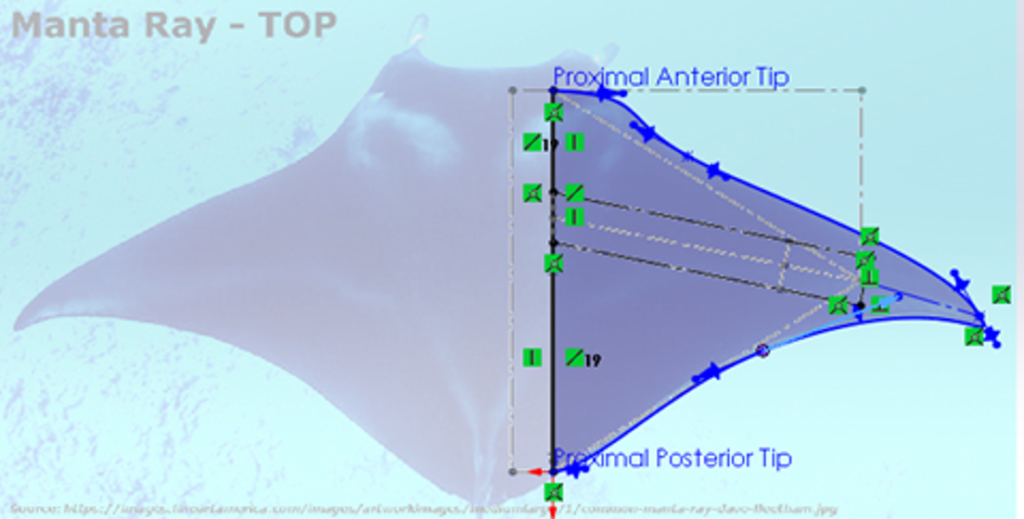

For the geometry of the wing surface, we took advantage of millions of years of evolution and took the general shape from that of a cownose ray. After making adaptations to suit our robot, the wing was then modeled in SolidWorks. A large cavity is placed inside the wing to accommodate the tensegrity beam skeletons, as well as two additional cavities to provide flexibility. Bending analysis and simulation was then performed in Fusion 360 to select a material with appropriate properties.
To attach the wing surface to the body, a two-stage flange was devised. The first stage is completely open and designed to be cast directly into the wing with barbs added for anchoring. A more closed off second stage is permanently attached to the first, and contains captured nuts to allow it to attach to the main body with bolts.
Body Design

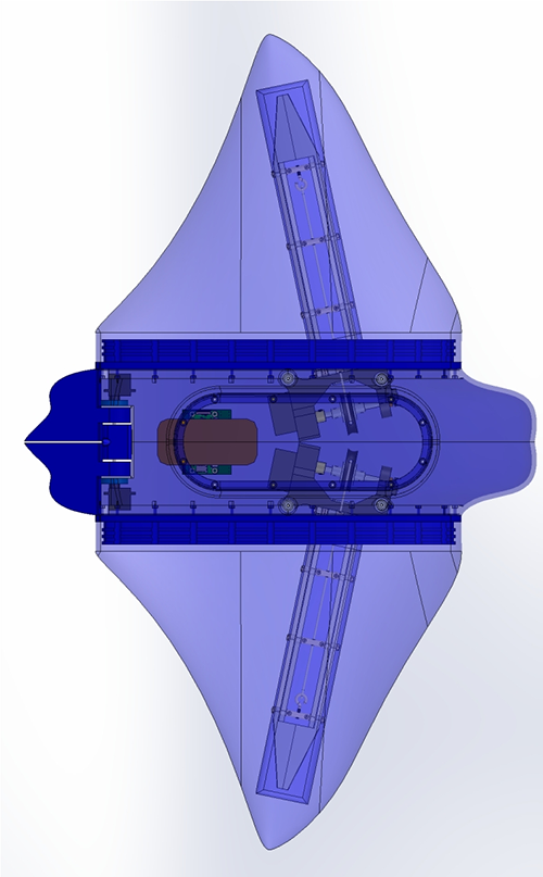
The rigid central body was designed to house and mount all of the internal components and hardware while mimicking the form of a cownose ray. This shape minimizes the frontal area, reducing drag. It was modeled in SolidWorks and Fusion 360. Simulations were performed to determine the centres of mass and pressure in order to estimate how much additional ballast would be required to make the robot neutrally buoyant.
Elevator Flaps
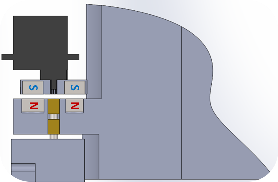
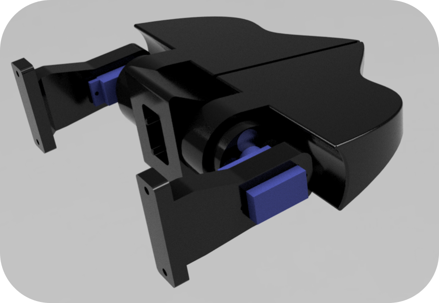
Two elevator flaps at the rear of the robot allow for the control of pitch and roll during swimming. Inside these flaps are an array of magnets with alternating pole orientations, while a mirrored magnet array is connected to servo motors within the body. This coupling allows us to actuate the elevators through the solid wall of the body, making the design inherently waterproof. These flaps are connected to the onboard IMU where feedback control actively steadies the robot during swimming.
Electronic Hardware
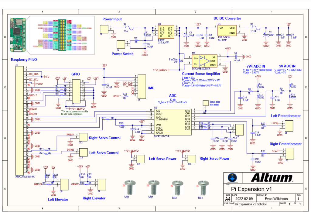
To actuate the cables, hobby servo motors were selected for each of the wings. Hobby servo motors are designed to output high torque for their size due to inherited gear ratios and include internal circuitry for closed-loop feedback control which leads to high positional accuracy. To drive the motors, pulse-width modulated signals and positional information are generated from a Raspberry Pi Zero. A printed circuit board (PCB) was designed to breakout the connections to the Raspberry Pi, allowing additional peripherals to be connected – such as an analog to digital converter (ADC) to capture data, an inertial measurement unit (IMU) to measure robot orientation, and a current sense amplifier to monitor battery power consumption.
Software and Control

The software application developed using Python 3 brings RAEMOND to life. Python 3 was chosen to take advantage of its vast library of available packages which saved tons of software development time. Key features of the application include object-oriented drivers, threading, and socket programming. The drivers initialize the peripherals such as setting up the SPI bus for the ADC or the I2C bus for the IMU and storing their data as attributes so they can be easily accessed at different points in the program. Threading allows all peripherals including each motor, each elevator, the ADC, IMU, blinking LED’s, data logging, and power monitoring to all run concurrently. This opens the opportunity for different features such as two wings running independent of each other for robot maneuverability, and data to be acquired at faster rates. Socket programming is utilized for wireless communication.
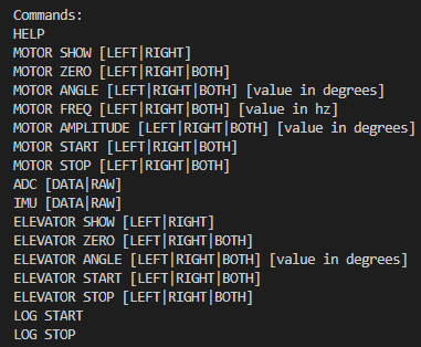
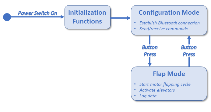
To optimize underwater testing and data collection, RAEMOND was designed to be completely wireless. Using the Raspberry Pi, Python 3, and Bluetooth socket programming, the user can send and receive commands to and from the device without the need disassemble the unit. In Bluetooth terms, the Raspberry Pi is configured to be the Server and a Windows 10 laptop running a Python script is said to be the client. Once a connection has been established, the user can send a variety of commands to the device such as starting the motors, logging the data, or acquiring a sample from the ADC or IMU. In addition to Bluetooth, the Raspberry Pi can be accessed using a Wifi SSH connection which allows full access to the device to make tweaks to the code.
In addition to the wireless commands, the user can simply press the pushbutton on RAEMOND to activate Flap Mode. In Flap Mode, the motors run their flapping cycle, the elevators become active for pitch correction, and the device opens a csv file and continuously writes data to it. When the user presses the button again, the motors and the elevators shut off and the data is ready for download. The user can then pull the data off the device using SSH communication. While not in Flap Mode, the device is configurable and readable using the Bluetooth commands.
Manufacturing
Tensegrity Beams

The linkages for the tensegrity beam were waterjet out of 0.25″ aluminum sheet metal, then finished on a mill. Mild steel threaded pins were turned on a lathe, then connected to the linkages using washers, lock nuts, and 3mm ball bearings. A milled aluminum plate allows the beam to be connected to the actuation sub-assembly, while turned aluminum standoffs provide mounting to the main body.
The wing tip, cable tensioners, and vertical members were all 3D-printed out of PLA. The mounting bracket and cam for the actuation sub-assembly were also 3D-printed. An aluminum D-shaft transmits torque from the servo motor to the cam, which is reinforced with aluminum plates.
Main Body
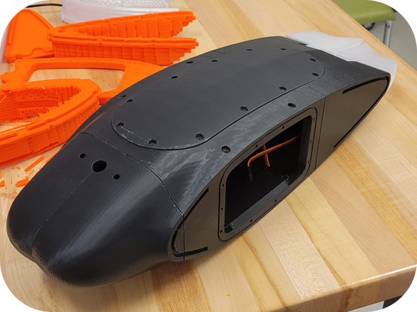
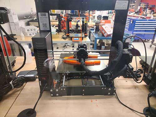
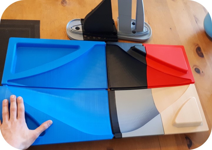
The body was 3D printed in four separate sections (including the lid) out of PLA, as well as the rear elevator flaps. These sections were sanded and joined using a quick-setting epoxy designed for plastic.
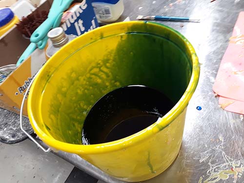
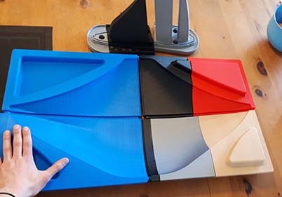
Wing Surface
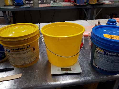
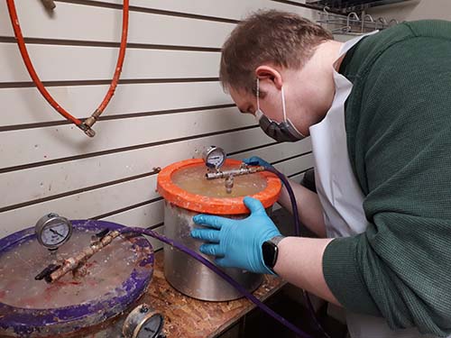
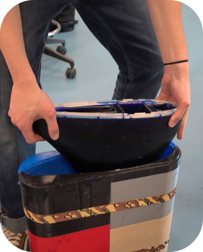
A test wing surface was cast for RAEMOND using VytaFlex™ 20 urethane rubber. To create the mold, sectioned 3D-printed parts were combined using a plastic welding adhesive, where wood filler was applied to the seams to create a continuous surface. The clam shell mold was then hand-sanded for smoothness, and clamped together using ratchet straps. A lid with inserts was used to create the cavity within the wing for the beam, as well as additional cavities for flexibility. Once the two-part polyurethane solution was mixed, it was degassed using a vaccum chamber to remove bubbles. Vaseline mold release was applied to the mold, and the solution was poured into it and allowed to set for 16 hours. A 3D printed flange was also cast directly into the material to allow for attachment to the body.

Electronics

The PCB was designed using Altium Designer and was fabricated by PCBWay. The board features 2-ounce copper, which is relatively thick allowing high current drawn from the motors to flow through the board with minimal loss. It is a 2-layer board comprised of through-hole and surface mount parts which were each hand soldered into place. Connector wires are also soldered directly to the board to minimize board size. Additional component pads were added to allow for future development, such as adding decoupling capacitors on power rails, or 0-ohm resistors to change pinouts.
Meet Our Team Members


Acknowledgements
Special thanks to our sponsor, the University of Tianjin, who gave us the opportunity to work on this project. In particular we would like to thank Dr. Jun Chen of the University of Tianjin for working with us and providing valuable insight into our design.
We would also like to express our gratitude towards our Capstone design course instructor, Dr. Roes Budiman, as well as to Dr. Artem Korobenko and Meghdad Gias, both from the University of Calgary. Our project could not have been a success without their guidance.
Lastly, we would like to thank both Aaron Machine Shop and Tactile Orthopaedics for their help in manufacturing, as well as the Schulich School of Engineering for providing funding.
Sponsors

Special Thanks
Design Tools

References
[1] T. Kemp, “Investigating Batoid-Inspired Propulsion: The Development, Testing, and Performance Analysis of a Tensegrity-Based Robotic Fin for Underwater Locomotion,” Apr. 2014, doi: 10.18130/V3CJ88.
[2] R. S. Russo, S. S. Blemker, F. E. Fish, and H. Bart-Smith, “Biomechanical model of batoid (skates and rays) pectoral fins predicts the influence of skeletal structure on fin kinematics: implications for bio-inspired design,” Bioinspiration & biomimetics, vol. 10, no. 4, Aug. 2015, doi: 10.1088/1748-3190/10/4/046002.
[3] J. Chen and Y. Wang, “Manta Ray Flexible Wing for Robot Development.”, University of Tianjin, Tianjin, China. Project Proposal, Sept. 2021.
Our photo gallery