Project Category: Multidisciplinary
Join our presentation
About our project
Ethylene is an important petrochemical; it is a cornerstone in producing polyethylene plastic, ethylene glycol and fertilizer. Ethylene production dominates Alberta’s petrochemical sector due to low feedstock costs. In an effort to diversify Alberta’s economy, the government of Alberta has incentivized the construction of petrochemical facilities including ethylene producing facilities. However, due to large capital costs and uncertainties, companies are risk averse when taking on large capital-intensive petrochemical facilities.
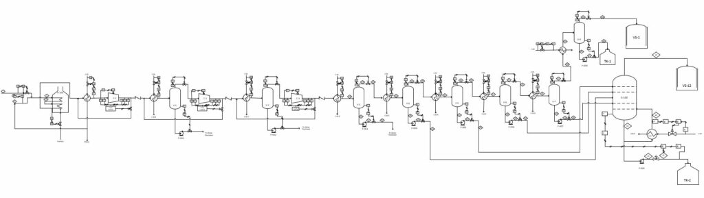
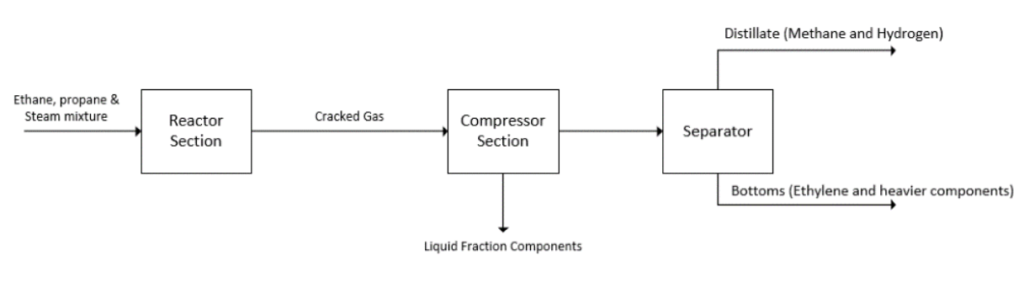
A solution is to adopt the construction of small-scale petrochemical plants. The objective of our capstone project was to design and optimize the reactor, cracked gas compressor, and demethanizer distillation column of a small-scale Ethylene plant (100,000 t/y); while accounting for process safety through process control loops, environmental regulations, and economic considerations to determine the feasibility of the plant.
Meet our team members

Samantha Brown
Major: Chemical Engineering

Christina Showalter
Major: Mechanical Engineering

Deston Yee
Major: Chemical Engineering
Details about our design
HOW OUR DESIGN ADDRESSES PRACTICAL ISSUES
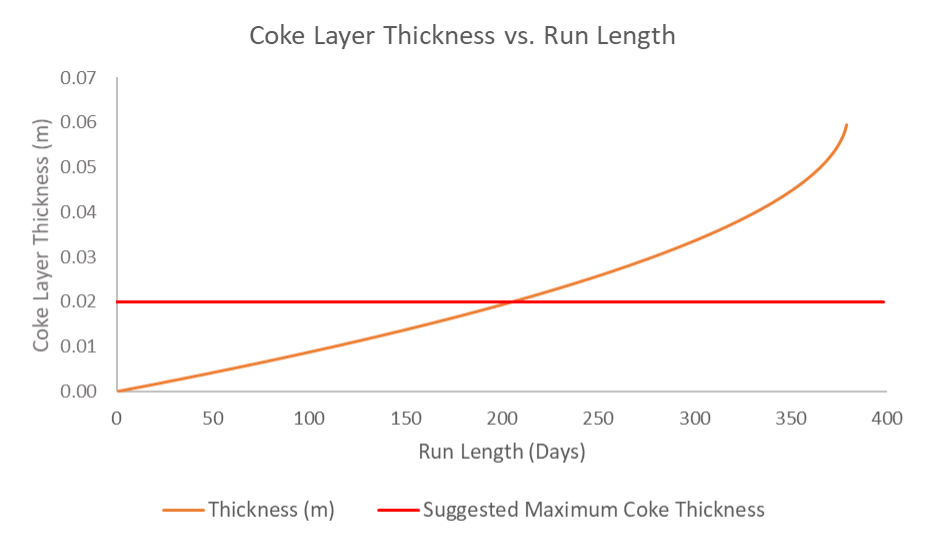
Coking in Reactor
One of the largest issues faced by ethane crackers is coke buildup in the reactors. Coke is essentially hardened carbon that is made as an unwanted by-product of reaction and lines the walls of the reactor. It was not possible to model coking in our process simulator, Symmetry, so we created a model of the reactor in Matlab that would account for the coking reactions. From our model, we found that the reactor tubes could run for 205 days before requiring 2 days of cleaning. The production rate of our original model was adjusted to account for coking and the new run lengths.
Fouling in Compressor
The main goal of the centrifugal compressor is to compress the cracked gas to a high pressure of over 3200kPa for the demethanizer inlet. A common issue in high pressure compressor applications such as this is the possibility of fouling. Fouling occurs as a result of polymer deposits forming on the compressor surfaces and impellers, negatively impacting the compressor performance. These polymers can form in a number of ways, including high temperature, presence of monomers, and unsaturates carried over from the cracking process. Performance can be impacted in the following ways: decrease in efficiency, increased discharge temperature, pressure drop, and increased vibration. Consequentially, the energy requirement can increase, thereby increasing the cost while ethylene production decreases to below the target needed. An integrated solution of an antifoulant coating on the compressor surfaces combined with regular wash cycles addresses the issue of compressor fouling by decreasing the temperature, dissolving polymers, and increasing corrosion and erosion resistance.
Achieving Separation in Demethanizer
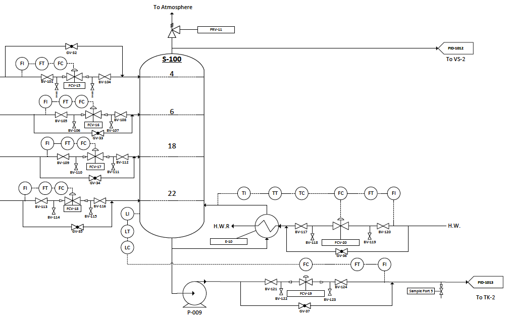
The purpose of the demethanizer is to achieve 98% of methane from the cracked gas stream. The largest issue faced with the demethanizer was to achieve this separation. In our process we have 9 different components with boiling points that are both near and far apart from each other. The wide range of negative boiling points makes achieving the separation specification difficult. To aid in separation the operating conditions of the demethanizer were set to high pressure and cryogenic temperatures; however, just changing the operating conditions could not reach the desired specifications. Therefore, multiple feed streams into the demethanizer at different operating conditions were used to aid in the separation process. To separate the cracked gas into different streams, a series of flash drums were used where the bottoms product was a feed stream into the demethanizer. The flash drums also remove excess water which prevent freezing and water reaching its triple point in the cryogenic demethanizer.
WHAT MAKES OUR DESIGN INNOVATIVE
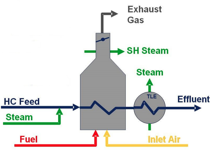
Wherever possible in the design process, we incorporated ways to save money, energy, and resources. We designed the plant to produce much of its own energy from methane and hydrogen that are by-products of the process. For example, in the design of the fired heaters, we used recycled hydrogen as fuel since hydrogen has a very high energy density and produces no greenhouse gas emissions. The remainder of the fuel is recycled methane. Methane is also used to power the turbines that drive our three compressors. After the furnace and compressor fuel requirements, there is still excess natural gas produced that could be used for other energy purposes.
We also implemented waste heat recovery in several parts of the plant. For example, exhaust from the furnace is used to preheat the reactor feed, which needs to be at 600°C. Also, heat recovered from cooling the very hot furnace effluent is used to generate dilution steam that is injected into the hydrocarbon feed.
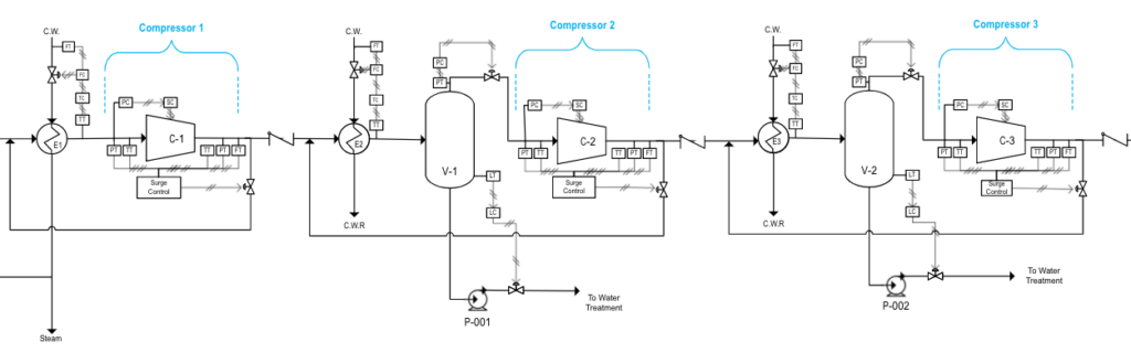
The compressor design was innovative in that it reduced the number of compressor units usually seen in large ethylene plants from ~5 to 3. This was achieved by implementing intercoolers between each compressor stage to reduce the outlet temperature while increasing the pressure to the desired value. Additionally, the compressor was optimized in such a way that the power requirement and cost were reduced. Instead of keeping a constant pressure ratio in each stage, the compression ratios were varied to find the optimal values that minimized the total power of the compressors and intercoolers, while still reaching the required pressure.
The design of our demethanizer was innovative as it reduced costs by limiting the number of demethanizer units required. In other designs, multiple demethanizers are used to achieve separation; however, our design uses multiple feed streams that connect to a single demethanizer. This reduces fixed, operational and maintenance costs by eliminating the need for additional process units. Furthermore, the last flash drum before the demethanizer is useful for removing most of the hydrogen and a large portion of methane that will be used as fuel for the fired heaters.
WHAT MAKES OUR DESIGN SOLUTION EFFECTIVE
Our design solution meets the majority of requirements that we created at the beginning of the project:
| Parameter to be measured | Criteria for product acceptance | Actual product |
| Plant throughput (t ethylene/yr.) | 100,000 | 104,406 |
| Reactor ethylene yield (%) | 75-85% | 63.5% |
| Reactor ethane conversion (%) | >50% | 82.8% |
| Compressor outlet pressure (kPa) | 3200 | 3250 |
| Methane separation in demethanizer (%) | 98% | 99% |
We did not achieve the ethylene yield requirement because we were able to maximize the total ethylene production with the current combination of ethane conversion and ethylene yield. Also, low ethylene yield does not necessarily mean losing money. Many of the other products are sold as valuable by-products such as 1,3-butadiene and propylene, or used as fuel in the plant like hydrogen and methane.
We also proved the design’s effectiveness by performing a hazard and operability (HAZOP) study for one major unit in the design, in this case the centrifugal compressor. Potential hazards and their risks were considered, with process loops addressing some of these issues, such as surge control, and fouling mitigation measures included. This effectively addressed the possible risks that could occur in compressor operation and provided realistic ways to prevent them.
HOW WE VALIDATED OUR DESIGN SOLUTION
Reactor Validation
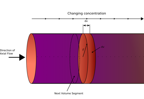
First, we modeled the plant design in the process modeling software, Symmetry. We chose a plug flow reactor (PFR) model for our tubular reactors in Symmetry. A PFR models fluid as flowing through the reactor as a series of infinitely thin coherent “plugs”, each with a uniform composition, traveling in the axial direction of the reactor. We inputted reaction equations and kinetics into the program and it developed a model of the reactor. To validate the results from Symmetry, we created a model of the reactor in Matlab, using the governing ordinary differential equations of a PFR to confirm the results obtained in symmetry. The results that we got from modeling the reactor were also validated against literature values to make sure they were within normal ranges.
Compressor Validation
The compressor design was validated in a number of ways. Initially, hand calculations were performed to determine the design parameters including inlet and outlet temperature and pressures, pressure ratio, volume flow, polytropic efficiency, and power. The only known condition for the compressor was the target outlet pressure for the demethanizer inlet, which was found from literature sources. Simulation of the compressor in Symmetry proved these hand calculations were correct, and made the design process more effective as the project progressed. Impeller selection was based on the compressor flow parameters and achieving optimal efficiency, with manufacturer specifications providing realistic impeller dimensions that were validated by textbook calculations. Finally, textbook reccomendations coupled with industry standards were used for the detailed mechanical design such as materials, connectors, and seals.
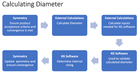
Demethanizer Validation
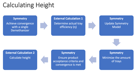
To validate the design of the demethanizer, simulation software including Symmetry and KG Tower were used. The results of the simulation were then validated by comparing the results to literature values. The process for calculating and validating both the height and diameter are outlined below.
FEASIBILITY OF OUR DESIGN SOLUTION
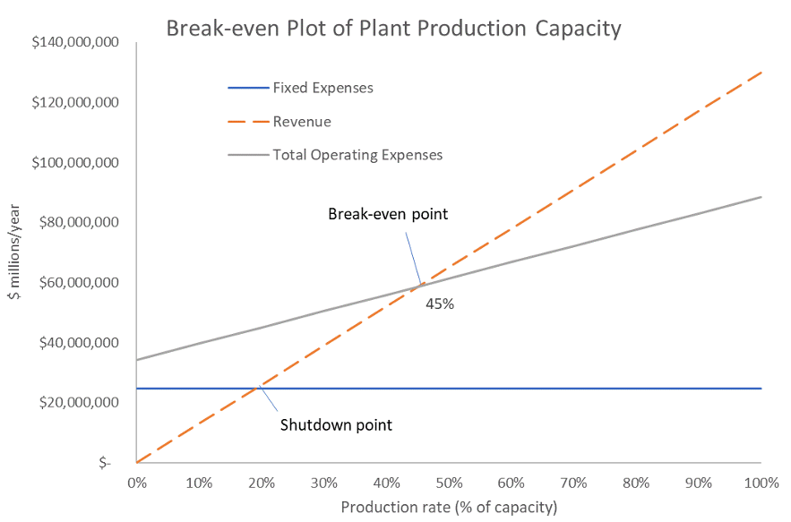
From our estimation of the total capital investment, operating expenses, and revenue, we found our plant design would be profitable when operating at greater than 45% capacity. The plant is designed to operate near 100% capacity.
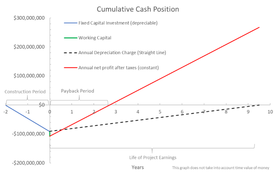
We performed an economic analysis on our design and the results showed high profitability. For an evaluation period of 10 years, the Net Present Value (NPV) of the project is $145M, the annual rate of return on investment (ROI) is 28%, significantly higher than the minimum suggested value of 16% for a project of this type. Also, the payback period for the total capital investment (time to earn back the initial investment) is only 2.7 years.
Partners and mentors
We want to thank the our academic advisor Dr. Michael Foley, our capstone instructor Dr. Roes Budiman and T.A. Saeedeh Saghlatoun who helped guided us through the process of the capstone project and provided invaluable feedback.
Our photo gallery