Project Category: Multidisciplinary
Join our presentation
About our project
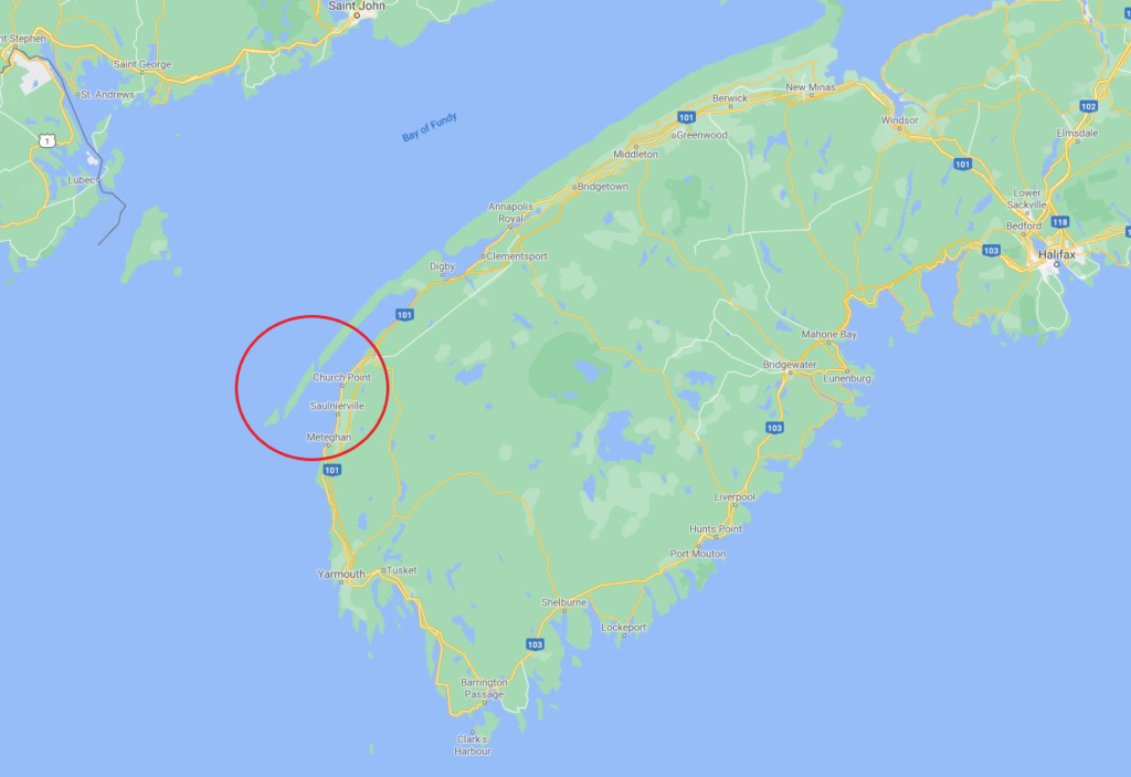
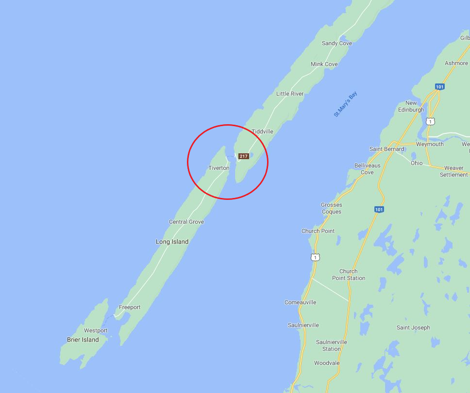
The ocean offers a vast source of clean and renewable energy for the world’s carbon-free energy demand. In Canada, one of the number of locations that offers a rich marine energy source is the Bay of Fundy, Nova Scotia. According to an assessment conducted by the province of Nova Scotia, the Bay of Fundy have an estimated total tidal power potential of up to 60,000 MW upon which up to 2,500 MW can be extracted without significant impacts on the marine environment. With such a vast area in the Bay of Fundy, variations in current speeds and direction can be wide-ranging. However, the team has looked into a more predictable and stable location which is found to be the Petit Passage near the Bay of Fundy. The Petit Passage has a mean power potential of up to 24 MW and the current characteristics are more predictable as the direction flows seaward to the Atlantic throughout the year. With that in mind, the Petit Passage is the chosen location for this project.
One way to harness this energy found in Petit Passage is by utilizing a hydrokinetic turbine, which converts the kinetic energy from the ocean currents into useful power. There are several technologies that exist, but the main technology focused in this project is a Horizontal Axis Hydrokinetic Turbine. The power capture and efficiency of the turbine is dependent on the design of the turbine blades. The primary objective of this project is to design an optimal hydrokinetic turbine blade based on the marine characteristics found in Petit Passage, Nova Scotia.
Meet our team members

Frans Joseph Arguelles
Energy Engineering Student

Joshua Yagyagan
Energy Engineering Student

Roniel Lim Gardonez
Energy Engineering Student

Chaodi Wang
Energy Engineering Student

Sheyhan Abeysinghe
Energy Engineering Student
Details about our design
HOW OUR DESIGN ADDRESSES PRACTICAL ISSUES
In recent years, there has been a growing concern for climate change and an increasing demand for clean, renewable energy. There have been a number of technologies, such as solar, wind, and hydroelectric, that tackles these issues and the development for these technologies have progressed greatly. However, though hydrokinetic turbines are somewhat similar to wind turbines, this technology is a relatively recent one and because of that, there has been a lack of research and development. As a result, there are currently no standards implemented and there is a lack of commercialized projects in Canada. This opportunity is too great to pass as the ocean provides great potential as an energy source; furthermore, since water is much denser than air, the turbine can be much smaller to generate the same amount of energy. Our hope, at least, for this project is to aid in the development for hydrokinetic turbines and to design a hydrokinetic turbine blade with a focus on the efficiency of energy capture.
WHAT MAKES OUR DESIGN INNOVATIVE
Our project addresses the marine characteristics in Petit Passage, Nova Scotia, and the blade design is tailored based on those characteristics. One marine characteristic that affects the efficiency of the turbine blade is the flow of water. Depending on the location, the current velocities and direction could fluctuate greatly and efficiencies can vary as well, which affects the total power output. Because of this, a resource assessment of the location is necessary. This can be done by taking the available historical data on Petit Passage current speeds and determining the most probable/most occurring velocity through statistics. Ideally, it is desired to operate at the most probable velocity and our blade is designed to exploit that by maximizing its efficiency at that desired velocity. However, there is a limit for the blade efficiency called the Betz-Joukowsky limit (59%) that applies to any turbine with fluid flowing through it. With that in mind, our goal is to get our turbine blade efficiency as close to the Betz-Joukowsky limit as possible.
The marine environment is a harsh and corrosive one. Although our primary focus was to maximize our blade efficiency as possible, it is also important to consider if the blade can survive the marine environment. Material selection is one of the key things that determines a turbine blade’s longevity. Based on the resource assessment, a material was closely examined and then selected to counter such environment. A structural analysis was also conducted to determine the bending stress areas caused by the thrusting force from the water current.
ENERGY RESOURCE ASSESSMENT
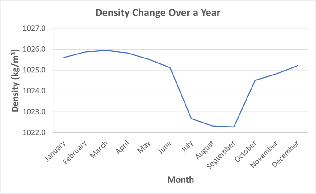
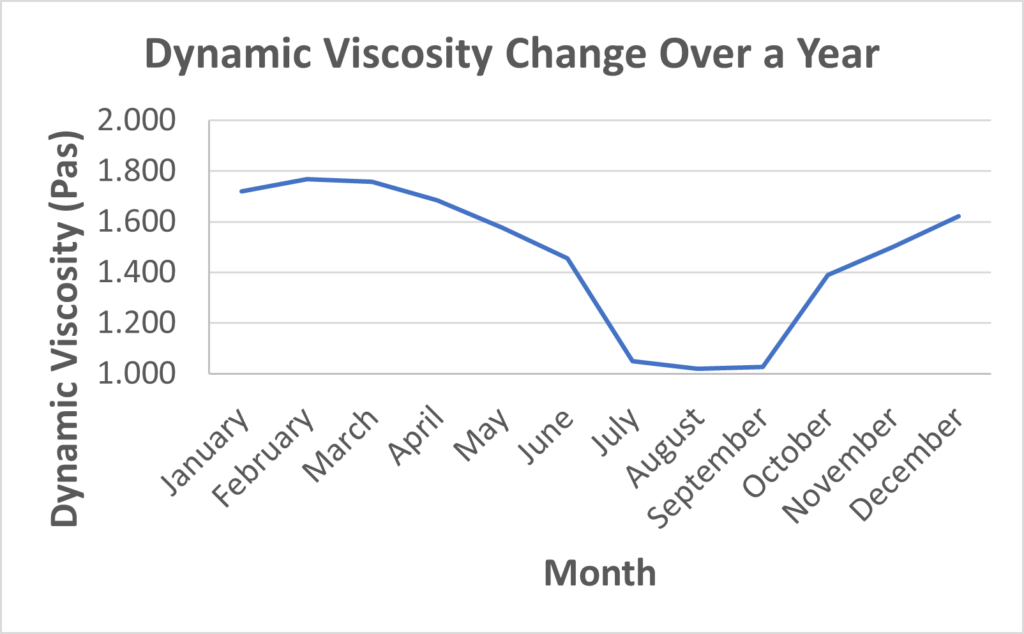
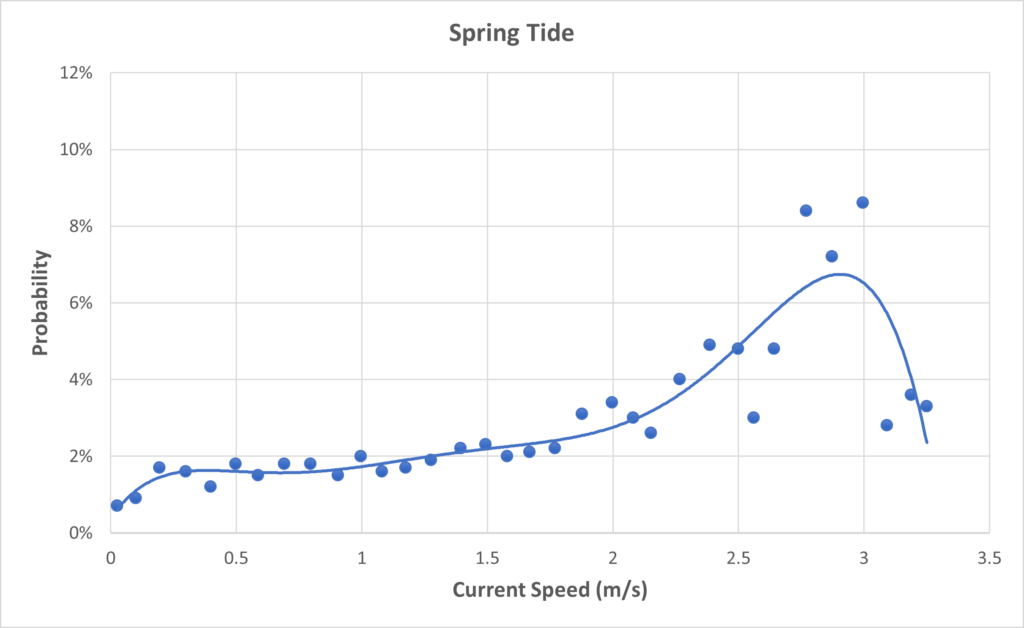
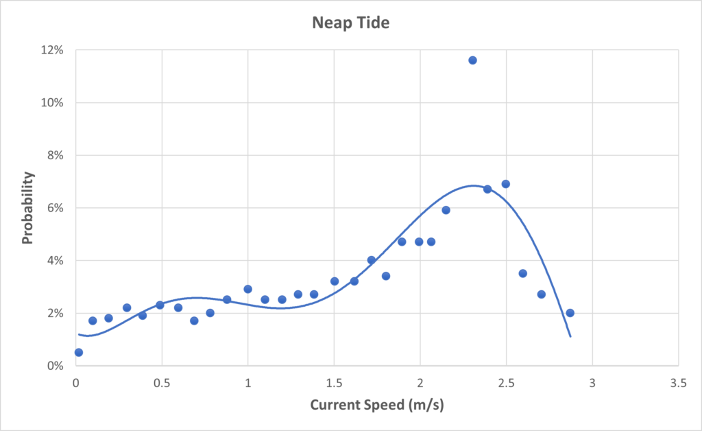
The ocean current properties undoubtedly changes with time. The ocean current properties have a significant difference during the summer season. This can be seen in the graphs below, the density and viscosity drops to as low as 1022 kg/m3 and 1.03 mPa·s, and rises as high as 1026 kg/m3 and 1.63 mPa·s, respectively. Velocity typically varies between the spring and neap tides. Spring tides occur after a new or full moon, where it has the greatest differences in the rising and falling tide levels; neap tides occur after the 1st or 3rd quarter of the moon cycle, where it has the least differences in the rising and falling tide levels.
DESIGN SOLUTION
HYDROFOIL SELECTION
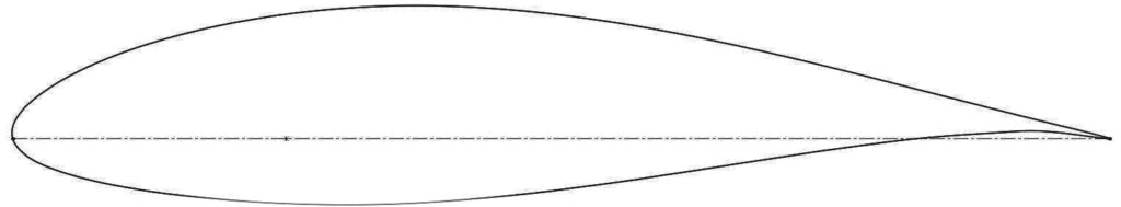
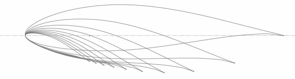
The performance of the turbine blade is dependent on the shape of the hydrofoil. A hydrofoil is used to produce a lift force on the blade for the turbine to rotate and produce power. Fortunately, hydrokinetic turbines and wind turbines are very similar; therefore, airfoils from wind turbines can be used as hydrofoils. A way to select the best hydrofoil is to look at a ratio called the lift to drag (L/D) ratio. It is ideal get the L/D ratio as high as possible; this means that the blade experiences more lift than drag as the turbine operates. The team has looked into different airfoils and it was determined that the NACA 63(3)-618 airfoil had the highest L/D ratio.
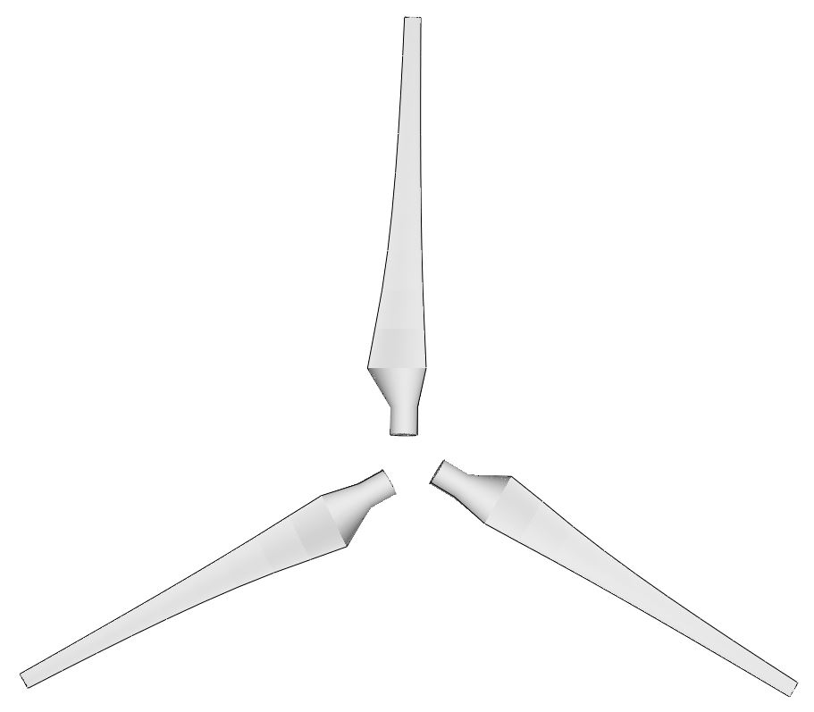
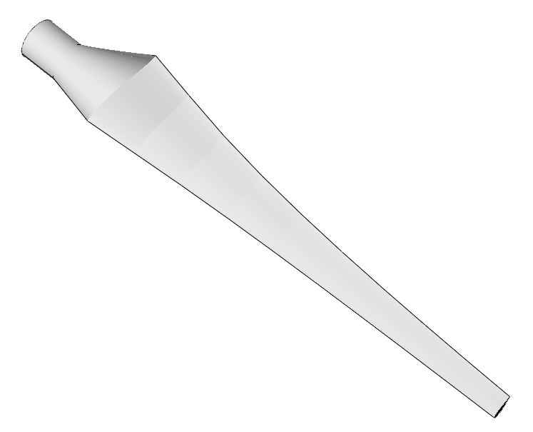
BLADE DIMENSIONS AND PERFORMANCE
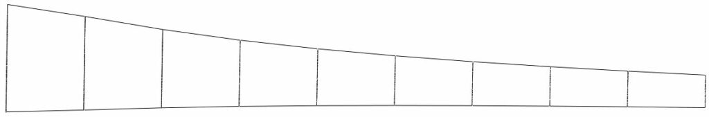
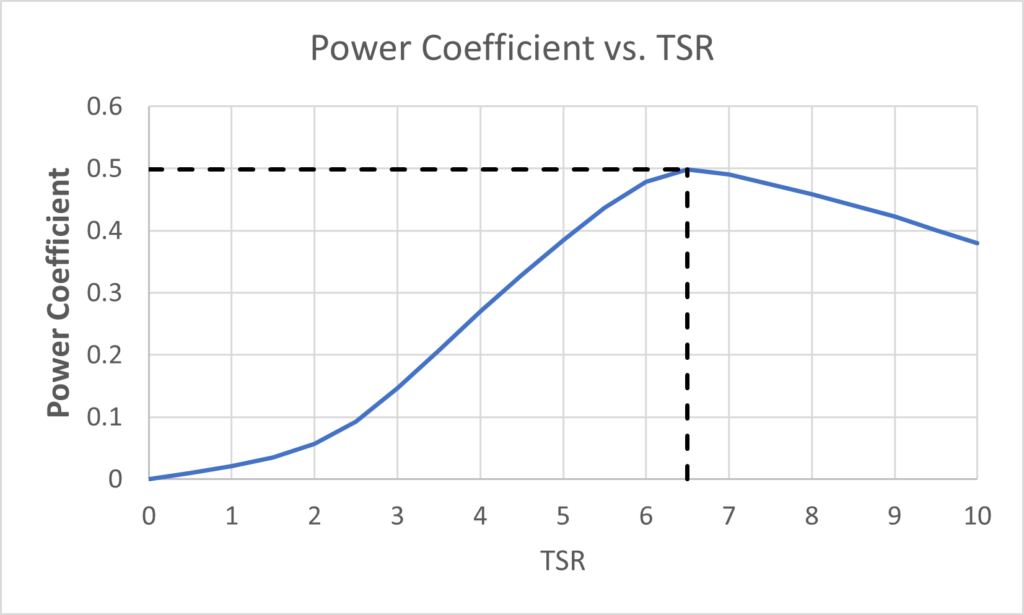
The rotor diameter for the turbine was decided to be 16 m with a hub diameter of 1 m; therefore, the turbine blade is 7.5 m in length. To determine the blade dimensions, the Schmitz-Glauert theory was used. This theory is somewhat similar to the Betz theory; however, it only applies to turbines less than 4 blades, which makes it applicable for this project. For the calculation, the blade is split into 10 elements and each element will have its own chord width and twist angle, β. The performance of the blade was calculated using the Blade Element Momentum Theory (BEMT). The BEMT, introduced by H. Glauert (1926), provides a framework to model the interactions between a turbine and the fluid flow. With this model, the turbine blade was tested with different current velocities and tip speed ratios (TSR) to calculate at which point the turbine will perform efficiently. TSR is the ratio of the blade tip speed in relation to the water speed and this parameter is used to generalize the variation in water speeds. The power coefficient, Cp, is defined as how the turbine blade can efficiently convert the water current to power. With those in mind, we can plot a Cp vs. TSR to determine when the blade will perform efficiently. As seen in the graph below, the turbine operates at an optimal TSR of 6.5 with a power coefficient, Cp, of 50%.
| Element | 1 | 2 | 3 | 4 | 5 | 6 | 7 | 8 | 9 | 10 |
| r (m) | 1.35 | 2.05 | 2.75 | 3.45 | 4.15 | 4.85 | 5.55 | 6.25 | 6.95 | 7.65 |
| Twist Angle, β (°) | 21.99 | 14.40 | 9.82 | 6.84 | 4.76 | 3.24 | 2.09 | 1.18 | 0.44 | -0.16 |
| Chord Length (m) | 1.098 | 0.901 | 0.735 | 0.613 | 0352 | 0.454 | 0.401 | 0.359 | 0.324 | 0.296 |
MATERIAL SELECTION
A careful examination of different materials for the turbine blade is necessary. The team has looked into a range of material types such as titanium alloys, glass fibers, and carbon fibers. When it came to choosing a material for our ocean turbine application, we reached the conclusion that the glass fiber reinforced polymer (GFRP) would be the best choice. Firstly, it is more cost effective than other options such as titanium. Additionally, it is more malleable than titanium. It has better water durability than a carbon fiber composite. This is due in part to the saturation levels for GFRPs; it becomes saturated much quicker than carbon fiber composites, meaning that the properties of GFRPs do not fluctuate as much as carbon fiber. Ultimately, the high strength-to-weight ratio was attractive. We did not want to make our turbine blade design cumbersome in its movement. In this case GFRPs serve well to not impede the performance of the blade.
| Elastic Modulus (GPa) | 72.3 |
| Poisson’s Ratio | 0.276 |
| Mass Density (kg/m3) | 2500 |
| Tensile Strength (MPa) | 567 |
| Yield Strength (MPa) | 3445 |
HOW WE VALIDATED OUR DESIGN SOLUTION
COMPARING POWER COEFFICIENTS
One of the goals of this project is to get the power coefficient of the turbine blade as high as possible; in other words, get it as close to the theoretical limit of 59% (Betz-Joukowsky limit) as possible. The maximum power coefficient of our blade design was found to be 50% and a question arises whether this efficiency is realistic or not. In reality, turbines can never reach the Betz-Joukowsky limit and typical large scale wind turbines have power coefficients that go up to 50-52%.
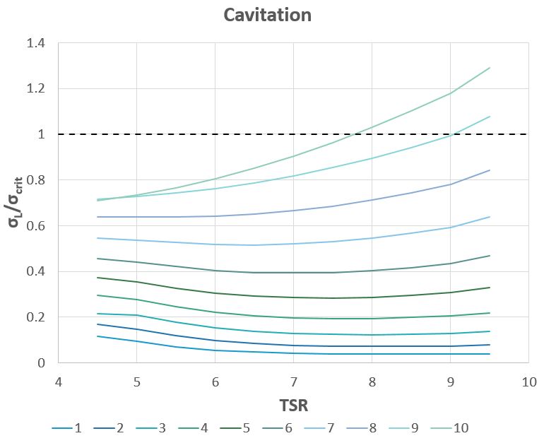
CAVITATION
Cavitation is a phenomenon where the formation of bubbles implode on the surface of the blade. This implosion can cause pitting in the hydrofoils, as well as accelerating long-term performance issues such as fatigue. Cavitation occurs when the hydrostatic pressure of the surface of the blade drops below the vapor pressure of the fluid. Due to the costs of manufacturing, installing, and maintaining hydrokinetic turbine blades, their design should take into account the avoidance of cavitation. Fortunately, at the optimum operating TSR of 6.5, cavitation does not occur with our blade design; it occurs at a higher TSR of 7.8.
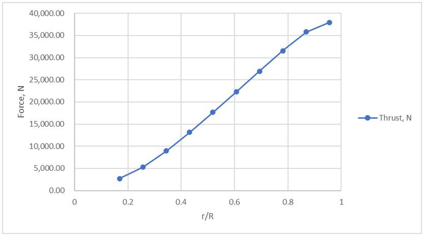
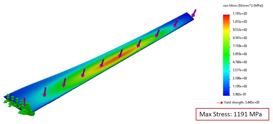
STRUCTURAL ANALYSIS
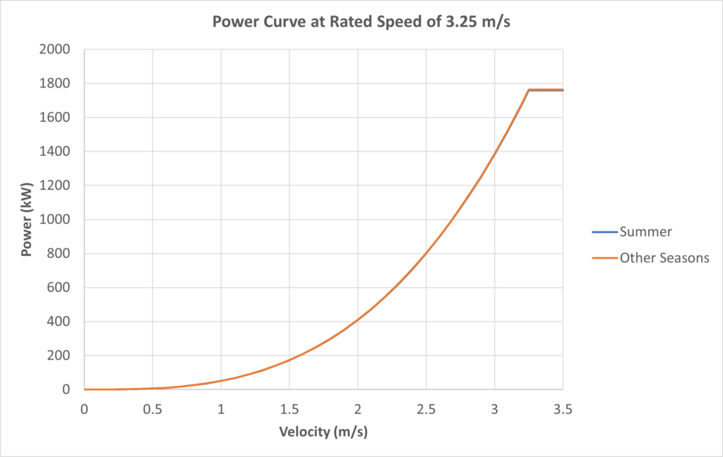
The turbine blade structure must be designed to endure the loads experienced in marine environments. When designing the blade, you can get it be as efficient as possible; however, this won’t matter if the blade cannot keep its structural integrity. The main force that mostly contributes to the bending stress on the blade is the thrust force, which is caused by free stream velocity of the water. The thrust forces is determined by expanding on the BEMT. The analysis will be based on the “worst-case” scenario when the blade is underwater while operating at the ideal TSR of 6.5 and Cp of 50%. This means a maximum recorded current speed, in Petit Passage, of 3.25 m/s and a maximum density of 1026 kg/m3 is used. The analysis is done by statically loading the blade as a cantilever beam while using the calculated thrust forces as the loads; the simulation is done using SolidWorks. It can be seen from the image below that the blade can withstand the forces at the set “worst-case” scenario, with a max stress of 1,191 MPa which is below the material’s yield stress of 3,445 MPa. With that, a factor of safety can be determined with a value of 2.9.
Acknowledgments
We want to thank the many people who helped us with this project. Our course instructor Dr. Roes Arief Budiman and teaching assistant Saeedeh Saghlatoun, who have guided us through the process with patience and great advice. Of course, our consultation of related subject matters with Dr. David Wood was invaluable.
Our photo gallery