Project Category: Multidisciplinary
Join our presentation
Meet our team on Tuesday April 13th, 2021 from 9:30am to 12:30pm. Looking forward to chatting with you and answering your questions!
About Our Project
Industry demand for automated manufacturing tools has increased. Some groups have specifically sought out solutions that would increase the productivity of manufacturing small workpieces using 5-axis CNC milling machines. The objective of our capstone project was to design and prototype an accurate automated rapid swapping-fixture mechanism that is compatible with a 5-axis milling machine.
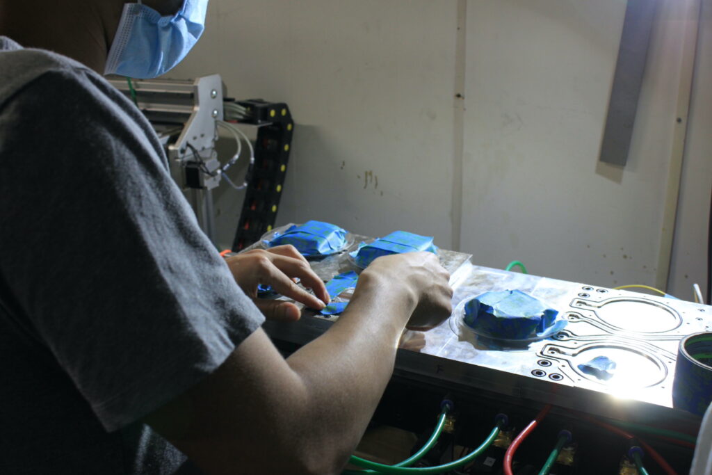
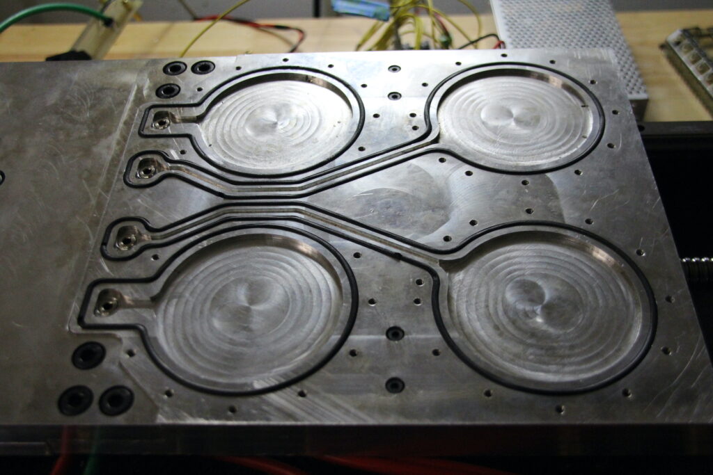
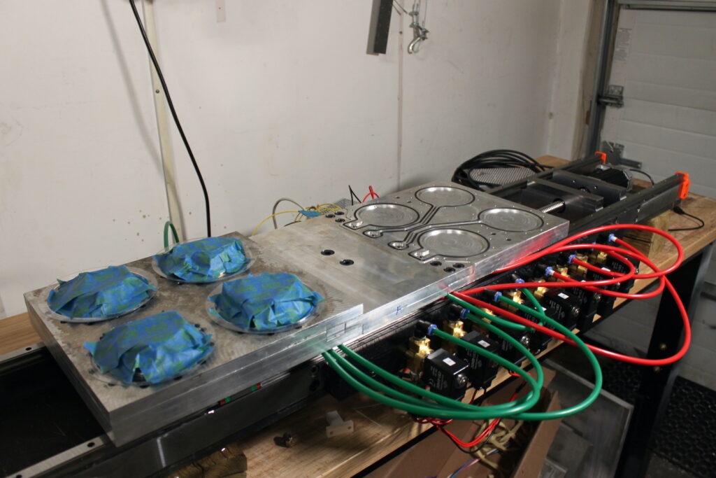
The swapping-fixture mechanism will maximize machine cutting time and optimize material handling by the operator. While the workpieces on the innermost plate are manufactured in the milling area, the operator will unload and reload workpieces on the outermost plate. After these processes are complete, the fixture plates will be swapped; then, the process will repeat itself. Research and careful selection of the mounting and actuation mechanisms guarantee the fidelity of the prototype. Further, our design accounts for external perturbations and risks during regular operation. Both analysis and testing on the assembled prototype validated the potential effectiveness of this project for use in the industry.
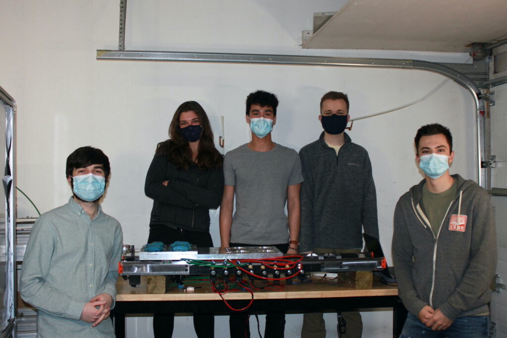
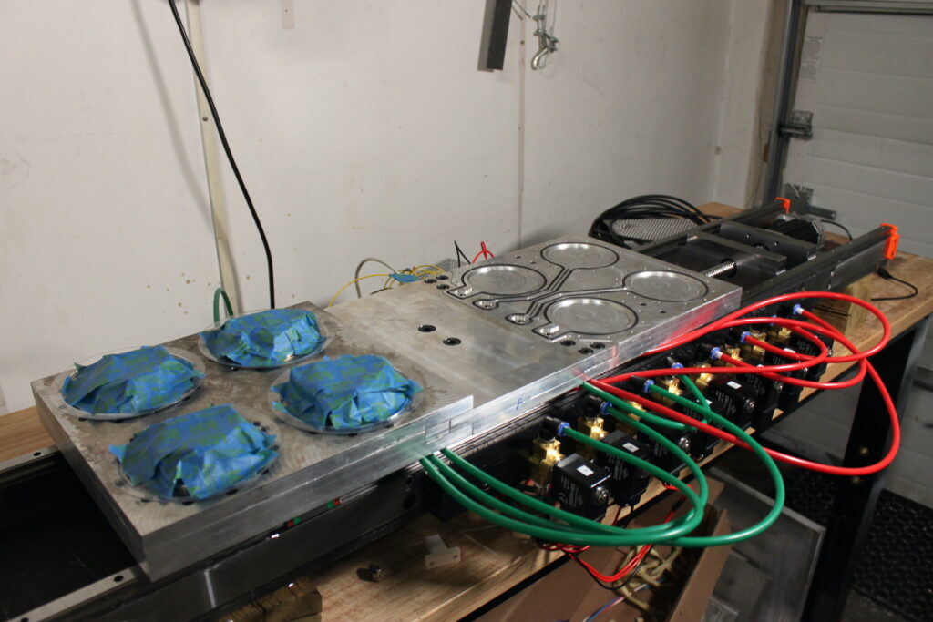
Prototype Overview
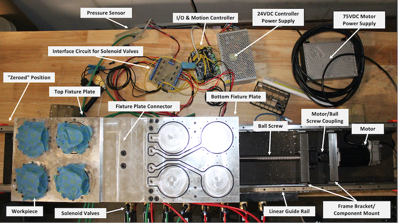
Two sub-systems are responsible for driving the functionality of our design:
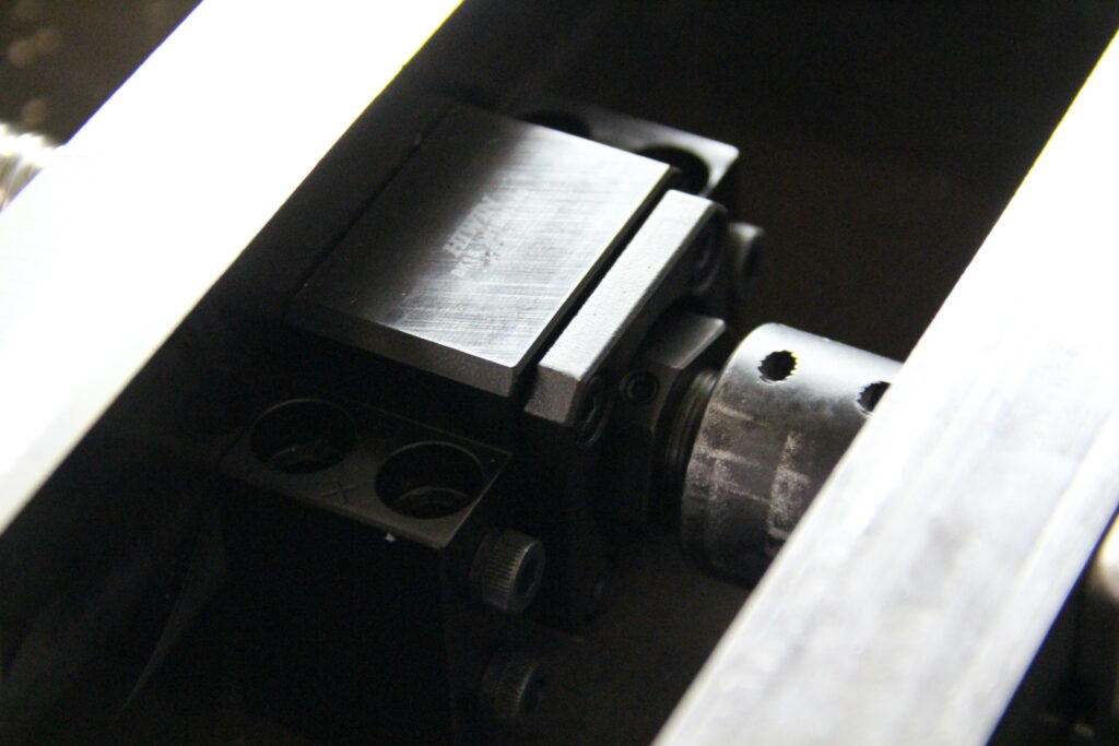
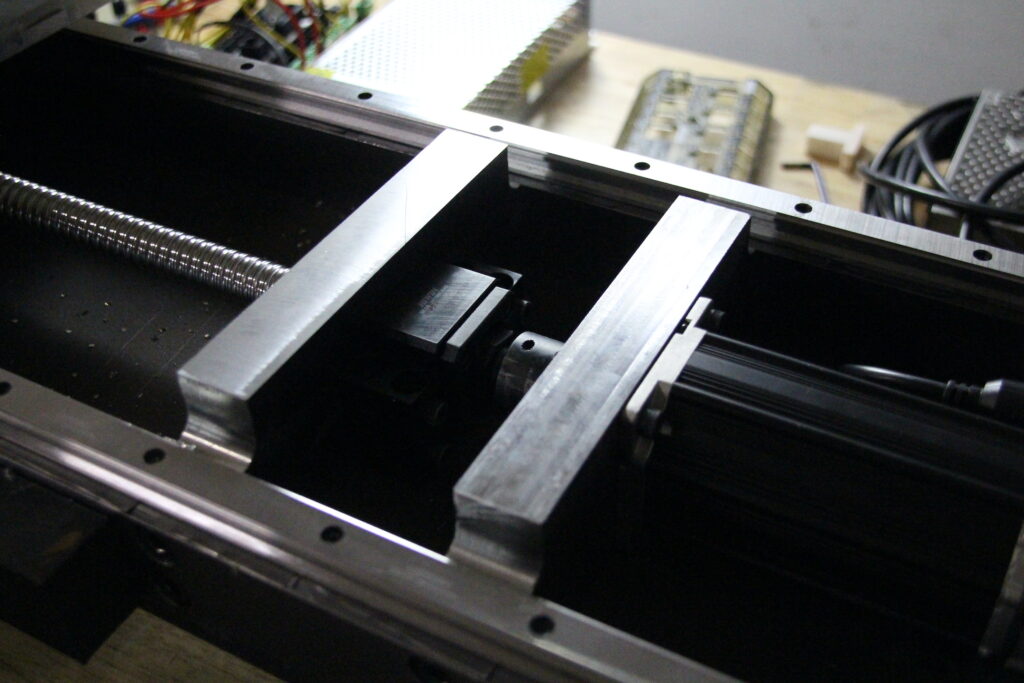
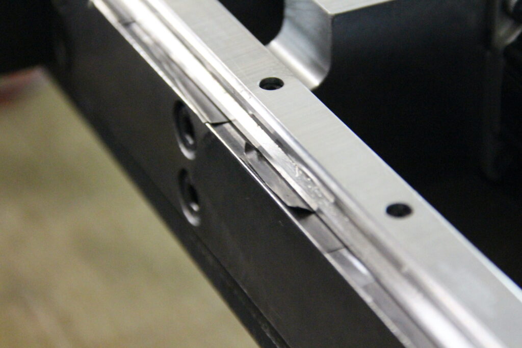
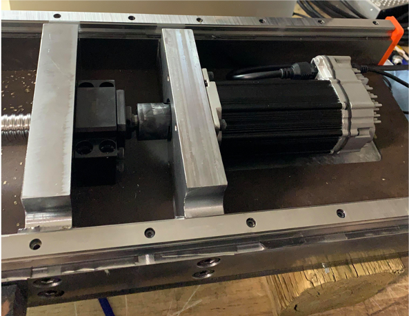
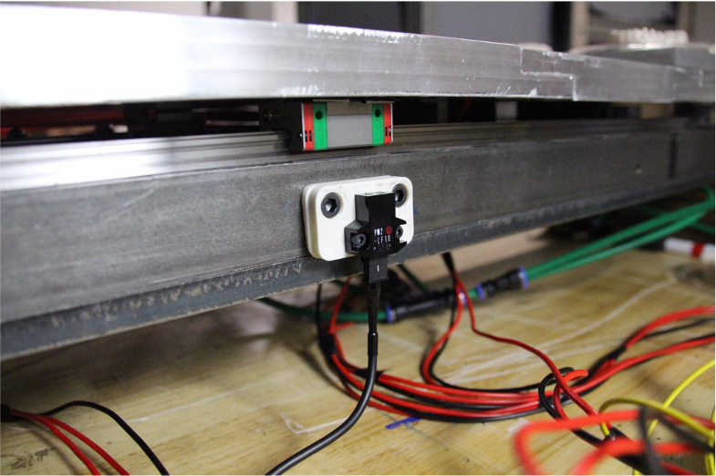
- The Actuation System, responsible for moving the fixture plates horizontally in and out of the milling area. This comprises a ball screw and support equipment; linear guideways and guide blocks; an integrated servo system; and a position sensor for zeroing the position of the fixture plates.
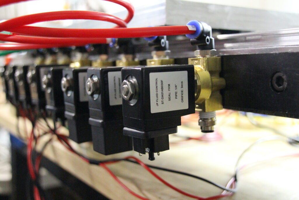
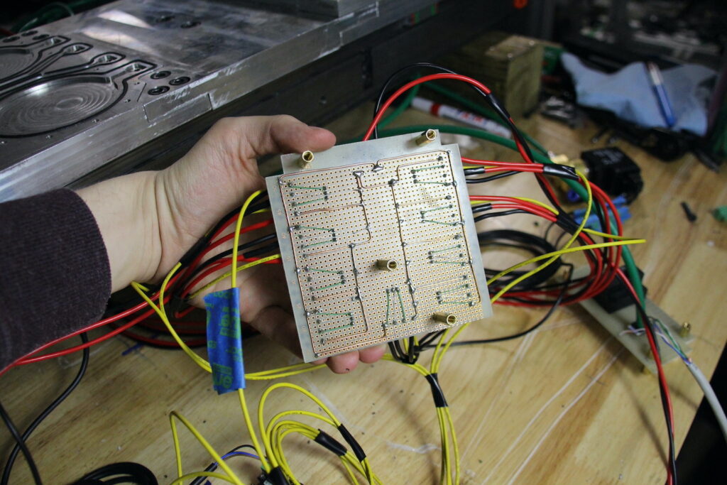
- The Vacuum Holding System, responsible for preventing workpieces from being displaced during the manufacturing process. This comprises a Venturi device, as well as a set of solenoid valves and vacuum sensors to ensure that each fixture plate is evacuated.
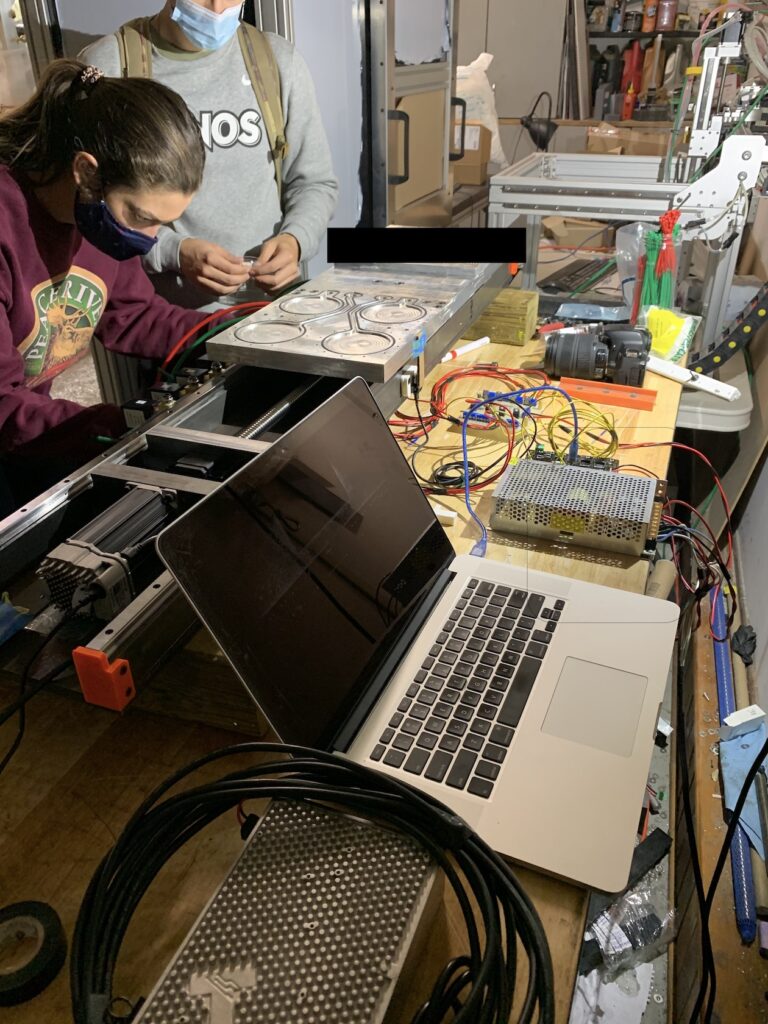
Our prototype is a demonstration of these sub-systems functioning independently of one another. The actuation system was driven and tested using open-source software from the distributor of our servo system. The vacuum holding system was validated using a direct-line connection to the Venturi device. Several features (such as the use of the position sensor or the vacuum sensors) will be fully realized in future prototype iterations due to some unforeseen challenges with the mechanical assembly. A proper user-interface (hardware-based or computer/tablet-based) will also ned to be developed in the future. Groundwork for the software design has been prepared and will be handed-off for future prototype iterations.
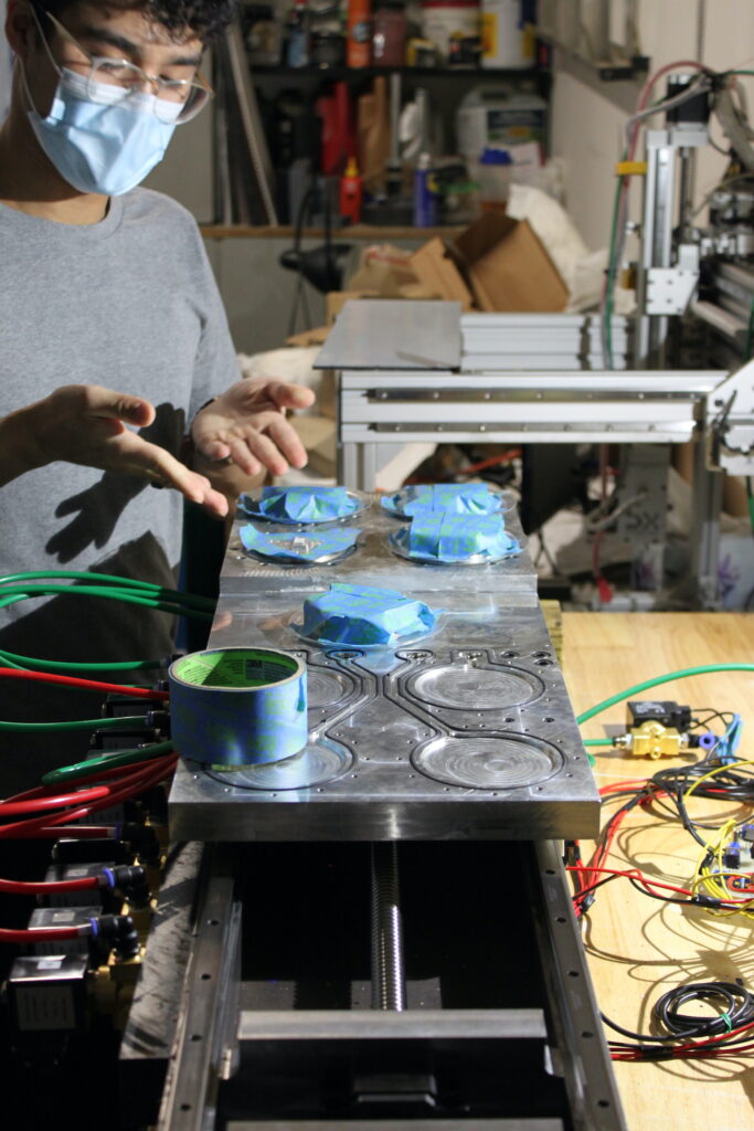
The Team
More About Our Design
HOW DOES OUR DESIGN ADDRESS PRACTICAL ISSUES?
Currently, the operator of a 5-axis mill must manually and individually swap out workpieces from the workspace before the manufacturing process can begin. Our team tested two methods of replacing and fastening for reference:
- Using mechanical vices, it took approximately 60 seconds to swap one workpiece.
- Using an individual vacuum holding, it took approximately 23 seconds to swap one workpiece.
The machine cannot run with an operator working inside the milling area, resulting in downtime which reduces both productivity and profit for the manufacturer. Thus, the above-two demonstrations yield a machine downtime of 60 seconds and 23 seconds, respectively. Please note that this does not account for additional time spent recalibrating the mill after positioning each workpiece.
Our prototype design directly addresses the above-mentioned issues by parallelizing the manufacturing and loading processes. It enables the operator to load multiple workpieces outside of the mill while previously-loaded workpieces are machined inside the workspace. Further, the high repeatability in the positioning of our assembly removes the necessity of recalibrating the mill after each swap. The toolpaths and reference positions established at startup should be consistent throughout the duration of the machine’s operation.
Using our prototype, we timed that it would take an average of 12.5 seconds to position a new workpiece on our fixture plate; thus, it would take 60 seconds to fully load one fixture plate with four blank workpieces. However, since this would occur while other workpieces are being manufactured, the process of replacing and fastening workpieces no longer contributes to the overall machine downtime. The downtime of the machine is reduced to only the time it takes to swap the fixture plates into the milling area. Our original acceptance criteria targeted a swapping time of five seconds. After assembly and testing, we successfully surpassed this and achieved a swapping time of 3.5 seconds. This yields a decrease of 94.2% and 84.8% in machine downtime compared to the manual processes involving mechanical clamps and the individual vacuum hold, respectively.
WHAT MAKES OUR DESIGN INNOVATIVE?
Our prototype cleverly automates a time-consuming manual manufacturing procedure. Currently, the operator is responsible for individually ensuring that workpieces are seated and held down; calibrating and initiating the manufacturing process; then removing and replacing the workpiece upon completion. As we explained in the section HOW DOES OUR DESIGN ADDRESS PRACTICAL ISSUES? the operator incurs a significant penalty in terms of productivity when performing this manual routine. There is significant machine downtime if the operator processes workpieces one at a time.
The current design is an innovative solution that benefits manufacturers in terms of product output and – by extension – profit. We are not aware of another machine that combines the action of swapping workpieces in and out of the machining area while providing a means to hold them down during manufacturing. Instead of machining a single workpiece at a time, operators using the current design can mill four complete workpieces at a time. By incorporating two trays, the machine downtime is negligible compared to the manual process. The operator can simultaneously initiate the manufacturing process on the innermost plate while loading new blanks on the outermost plate. The loaded outer plate can be swapped into the workspace immediately after the machining is complete, while the completed set can be removed and exchanged for new blanks. In future iterations, our team is confident that the design could be scaled up to incorporate more workpieces depending on their dimensions or the size of the mill being used.
WHAT MAKES OUR DESIGN SOLUTION EFFECTIVE?
Actuation System
Our prototype acceptance criteria specified a positional accuracy of 30um (0.001”) for the fixture plate assembly in the x-axis; as well, a maximum swapping time of five seconds. The accuracy specification was a requirement to ensure that the fixture plate assembly reliably returned to the same position after every swapping action. Focusing on the repeatability of the linear actuator gave us confidence that the calibration of the 5-axis mill would remain valid throughout operation. This significantly reduces the overall downtime of the machine, along with the consideration for the maximum swapping time. These parameters guided the sizing and selection of key machine components. Some key outcomes from the procurement of components in the actuation system were:
- The integrated servo system that was used to drive the actuation system was originally selected with a repeatability of 0.03 degrees with a peak torque of 0.8 Nm on a 24VDC supply. During assembly and testing, we realized that we would require a more robust motor to drive our mechanical design. Thanks to our sponsoring company, we were quickly able to exchange this for a similarly precise motor that operated with a peak torque of 5.8 Nm on a 75VDC supply.
- The ball screw and ball screw support units were selected such that they would provide highly-precise linear motion. Design considerations were made with respect to stiffness, critical speed, torque and load (among other things). To reconcile precision with cost, we were able to select stock components from the supplier.
- The linear guide rails and blocks were selected to provide a smooth, low-friction pathway for the fixture plate assembly to move along. These were selected to minimize the deflection of the ball screw by considering the load of the fixture plate assembly and the cutting force of the mill. We also selected a dust-proofing option to minimize potential obstruction from the shop environment.
- The frame components were machined to maximize flatness and rigidity. It was important that all members were level and mounted to be square with one another. The flatness of the side members was particularly important to ensure that the linear guide rails rested flat and provided an unobstructed pathway for the fixture plate assembly.
Vacuum Holding System
The vacuum holding system is designed to guarantee the reliability of our machine throughout the manufacturing process. Several design decisions ensured that the force of the mill could not unseat any workpieces during operation and that workpieces could be positioned consistently on the fixture plate assembly:
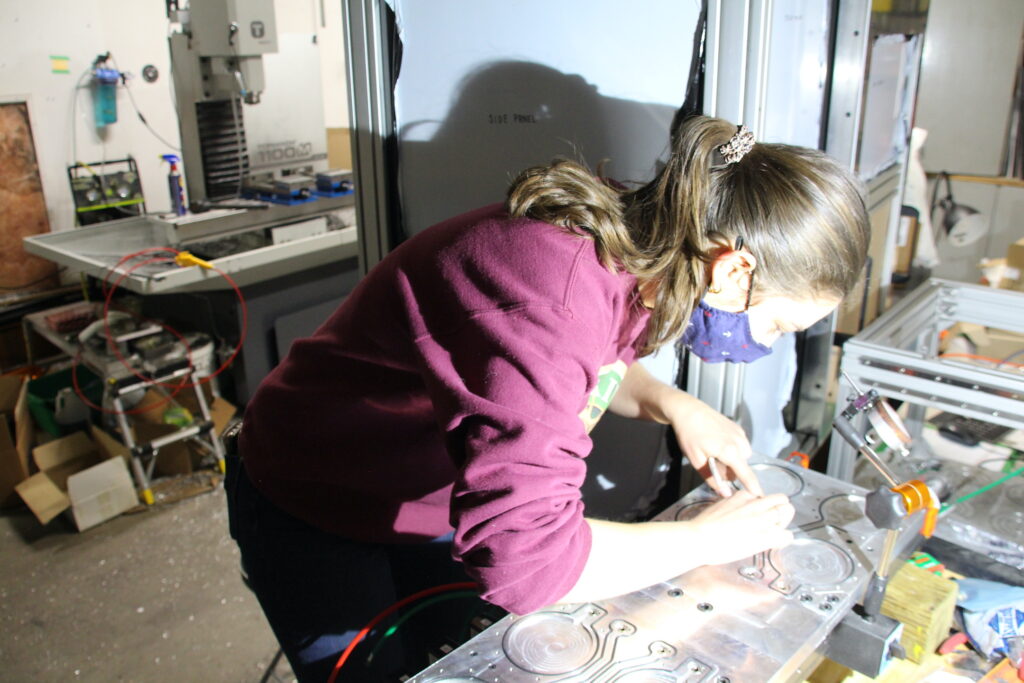
- The area for each workpiece on the surface on the fixture plate has a key sliding-pair interlocking system (ie. a grooved spot on the fixture plate that fits into the bottom of the workpiece) that only allows the workpieces to be mounted in a single orientation and ensures consistent alignment.
- The fixture plate is evacuated such that each workpiece is held with an approximate force of 49.7N. This considers the quality of machined workpieces by mitigating the risk of them becoming unseated during operation.
- The solenoid valves were selected with a kV value (a measure of the volume of air that can flow through the valve per unit of time) of 0.2 m3/hr. This ensured that each workpiece could be evacuated in less than two seconds so that the process would almost go unnoticed by the operator.
HOW DID WE VALIDATE OUR DESIGN SOLUTION?
Positional Repeatability
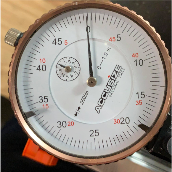
For this design to be effective, the actuation system of our machine had to have a repeatable actuation within 30um (0.001”). To ensure these metrics were met, we had the fixture plates moved to the machine’s initial position and calibrated a dial gauge that was pressing on the plate. This gauge had a precision to in. 15um (0.0005”). After the dial gauge was calibrated, the plates were moved to the swapped position and then moved back to the initial position. The dial gauge was recorded and would indicate a deviation in the position of the plate. The test was repeated several times, demonstrating a consistent repeatability less than 15 um, which exceeds our acceptance criteria.


Swapping Time
One of the key improvements of this design was to increase the efficiency of production. This meant that the speed at which the fixture plates could swap had to be as fast as possible, since that would be the only downtime for the mill. We performed test situations where a manual clamping system was timed (60 seconds), and a manual vacuum system was timed (23 seconds). We tested different swapping speeds for our fixture swapping device to find the optimal speed, keeping in mind the voltage and torque restrictions on the motor. We determined that the fastest speed our motor could handle was 1950 rpm, resulting in a swapping time of 3.5 seconds.
Vacuum Strength
To ensure that no workpieces move while in transit or during milling, a vacuum is applied to the bottom of the workpieces. The force of this vacuum must be stronger than the force of 17.9N created by the mill spindle. Our method of validating the strength of the vacuum force used a pulley weight scale. Once a vacuum was established on the workpiece, the weight pulley was attached to the top of the workpiece and someone began to pull on the pulley. The scale would measure the force being applied in the upward direction until finally the workpiece was removed. The point at which the workpiece was removed was recorded to be the vacuum force being applied to the workpiece which was 49.7N
FEASIBILITY OF OUR DESIGN SOLUTION
The components of the mechanical assembly were selected with the caveat that they must primarily be machined in-house using our sponsoring company’s equipment. In the case of oversized components, we outsourced the manufacturing to a third party. Some considerations for the parts that needed to be manufactured were:
- Ensuring that components (ie. frame side members and brackets) could be divided into smaller parts that are easier to machine using the available in-house mill.
- All components were designed using simple geometries, standard dimensions and with the intention of machining them using standard equipment. This minimized the amount of material removed during manufacturing and maximized the rigidity of the assembly.
Several factors influenced the procurement of components ordered from online and local distributors:
- Cost-effectiveness was heavily weighted when choosing between a set of options. If two options yielded the same functional outcome, we typically selected the part that cost less.
- We did not require our prototype to be built using any custom components (aside from what was required to be manufactured). All electrical and supplementary mechanical components were ordered from stock with delivery times less below one month.
- If purchased in bulk, most components were typically available at a discounted price per unit.
If our machine were to ever be mass-produced, we can expect that identical models of the prototype can be assembled in a reasonable time frame with a low component-wise cost and relatively straightforward manufacturing.
Our Partners and Mentors


We would like to extend our gratitude to our sponsor, Stephen Wong, and his wife, Carrie MacDermott, for their tireless commitment to the success of our project. They went above-and-beyond as mentors and devoted countless hours of their personal time to ensure that we achieved best possible outcome. We cannot thank you enough. This would not have been possible without both of your support!
Additionally, we would like to thank our course professor, Arief Budiman, and academic advisor, Dr. Jeff Pieper, for their continued guidance, support and encouragement throughout the school year. We appreciated you pushing us to complete this project amidst unusual and uncertain circumstances, and are proud of what we have to show for it.
Our Photo Gallery
