Custom Power Distribution Module (PDM) for an FSAE Race Car
Project Category: Electrical
Team Ownin With Onen
Join our presentation in-person at the 2022 Engineering Design Fair
April 5th (9:30 a.m. to 1:30 p.m. MT)
About our Project
Background
The University of Calgary FSAE Schulich Racing (SR) team is an interdisciplinary team of students that design, manufacture, and race a 1/3 scale Formula 1 race car. In SR’s pursuit of continuous improvement, they have identified an opportunity to revamp the car’s power distribution system. The team is seeking a bespoke solution that meets or exceeds the specifications of the current third-party power distribution module. This includes increasing the number of current protected outputs on the car and consolidating external circuits to minimize its weight, cost, and complexity.
Our Solution
Our team designed a solution that powers and manages all endpoints for the SR car’s electrical system including the:
- Engine control unit
- Dashboard display
- Fuel pump
- Various sensors
- Driver controls
The system provides additional protected outputs and the ability to broadcast specific messages for vehicle control, display notifications, and debugging purposes. It also contains critical safety features such as a shutdown circuit to safely disengage power to the car and reverse battery protection. Our solution was designed following an iterative and modular process to create a system that can be scaled easily by the team in the future.

Comparing our Design
Existing Solution
- Fifteen protected 12V Outputs
- No protected 8V Outputs
- No protected 5V Outputs
- Fixed Design
- No PWM Control
- 260 grams
- Current Sensing
- No Shutdown Circuit
- 11 x 13 cm
- Limited CAN Features
Our PDM
- Sixteen protected 12V Outputs
- One protected 8V Output
- Eight protected 5V Outputs
- Customizable Design
- PWM Control
- 140 grams
- Current Sensing
- Shutdown Circuit
- 17 x 12 cm
- Unlimited CAN Features
HOW OUR DESIGN ADDRESSES PRACTICAL ISSUES
When designing an electrical system, engineers must take special care to ensure that the power being supplied to all the electrical components will meet specifications. As such, the design of a safe and reliable power distribution system is critical for ensuring the success of any project that involves electrical systems. In a high-performance automotive application, key design considerations for a power distribution system must also consider minimizing mass, size, and overall complexity.
A basic design alternative for power management in an automotive application is the use of fuses. While fuses do protect electrical components in the event of an overcurrent scenario, they are relatively heavy and occupy lots of space, which hinders the performance of a race car. Previously, SR chose to distribute power using a third-party device. While the third-party product offered many benefits when compared to the basic fuse alternative, the device did not have enough power outputs, lacked customizability, was high cost, and required the use of additional external circuitry to power necessary devices on the car.
Our solution has been designed to meet both the race car’s current and future power distribution requirements. At the same time, it minimizes complexity by consolidating all additional circuits and the design is highly compact which minimizes the overall mass and size. The design features numerous safety features and is highly cost-effect when compared to the third-party power distribution product.
WHAT MAKES OUR DESIGN INNOVATIVE
One of the main focuses when designing our project was ensuring that it was well suited to the rapidly evolving nature of racecar design competitions. Year after year, the Schulich Racing car gains additional features and new ambitions are formed. Existing solutions often lack the characteristics and customizability to be suited to such an environment. We’ve improved on such solutions by:
- Creating a scalable design, allowing other endpoints to be easily integrated and powered by our design in the future
- Using electronic fuses for endpoint power control eliminates the need to replace or manually interact with traditional fuses
- Creating a custom PCB design to allow for the integration of our design with future team-built hardware designs
- Using a holistic approach to power distribution and current monitoring
- Utilizing onboard power regulation to power lower voltage endpoints
- Minimizing the cost of our product to be 90% lower than existing power distribution modules for racing applications
- Incorporating CAN communication to broadcast essential endpoint data to other vehicle modules
- Protecting each endpoint from fault conditions and implementing safety functionalities such as an emergency shutdown circuit and reverse battery protection
WHAT MAKES OUR DESIGN SOLUTION EFFECTIVE
With the advantage of designing a custom solution for the Schulich Racing team, we could make decisions focused specifically on catering to the needs of the race car. This application-specific focus allows our design to be more effective at meeting the needs of the Schulich Racing vehicle than other products on the market while also utilizing modern technologies that outperform traditional fuse boxes which are commonly used by competing FSAE teams. Our solution sought to outperform existing solutions and the FSAE competition through the following features:
- All power distribution and voltage regulation circuitry are integrated into a single PCB
- Providing multiple voltage levels, spare outputs, current limits, and trip time delays means that our PDM will be able to power almost any automotive device that Schulich Racing may add in the future
- Application-specific diagnostic information improves the team’s ability to debug future electrical issues on the vehicle
- Enhanced safety as a result of the diagnostic information provided by electronic fuses, allowing for constant monitoring and rapid response to fault conditions
HOW WE VALIDATED OUR DESIGN SOLUTION
Our approach to design validation relied heavily on segmenting our planned overall design into its major components and assembling a PCB for each. We designed PCBs for our microcontroller, power regulation, power shutdown, and electronic fuse modules. Individually, we used these PCBs to conduct targeted test cases, as well as connect them together to verify that our designs could be successfully integrated.
Our final integrated PCB was validated by conducting thorough test cases prepared prior to its arrival. The designed test cases verified every aspect of our design, from basic fuse control to the complex monitoring and fault detection routines, and finally, connecting our design to a test wiring harness which emulates the operation of the real car.

FEASIBILITY OF OUR DESIGN SOLUTION
Since our design is anticipated to be used in future generations of the Schulich Racing racecar, delivering an operational minimum viable product was of utmost importance. To ensure our design would be successfully integrated and used in the years to come, we made the following considerations:
- The cost of our solution is 90% lower than the existing solution
- Utilizing a microcontroller family with mature design tools, abstraction libraries, and an easily integrable operating system to minimize the firmware development burden
- Researching commercial and hobbyist designs aimed at solving similar problems to find commonalities, pitfalls, and areas of improvement
- Completing frequent and iterative testing of core circuit designs on test PCBs
- Defining the project scope with tiers of complexity to ensure a minimum viable product is attainable, with the option of adding more complex features
- Leveraging previous experience with specific PCB design tools and firmware development suites
- Reaching out to previous internship mentors for design feedback
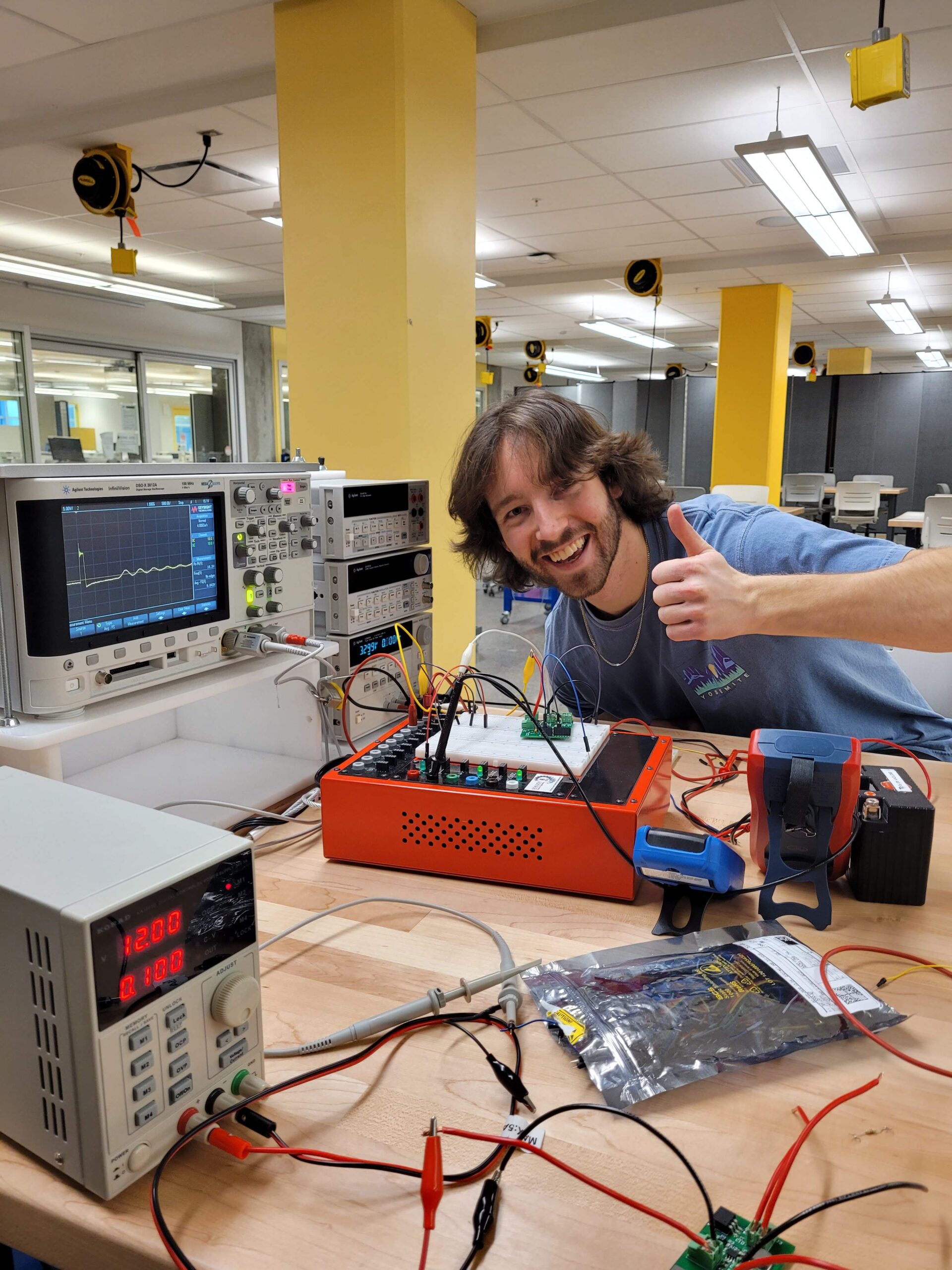
Meet Our Team


Details about our Design
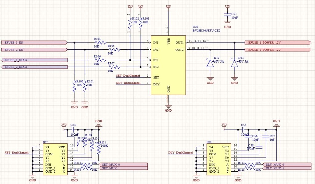
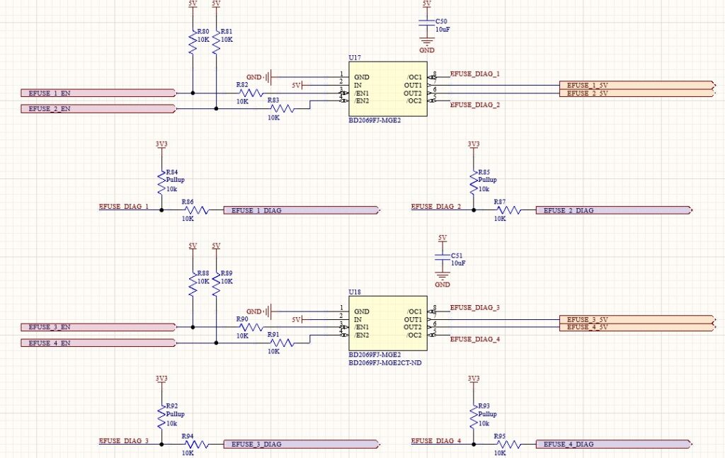
eFuses
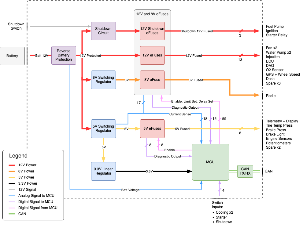
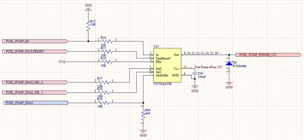
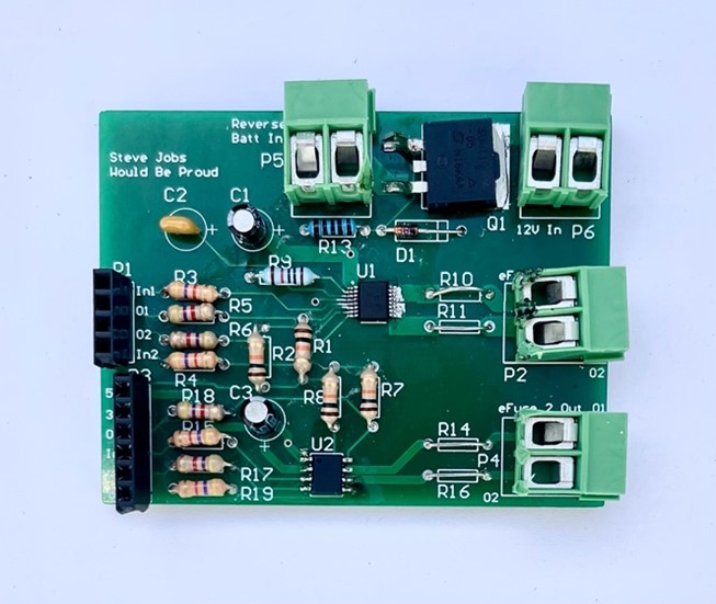
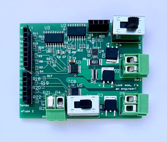
The eFuses handle power switching from the 12V protected rail and the power regulation module to all electrical devices in the vehicle. The MCU directly controls power switching while also receiving diagnostic and fault information from each eFuse. Our eFuse modules also contain the hardware to allow for firmware selectable current limits and delays to match the electrical characteristics of any device that needs to be powered.
An eFuse, or electronic fuse, is an integrated circuit that acts as a power switch while also providing fuse-like overcurrent protection and other electrical protections including over-voltage protection, under-voltage lockout, and thermal shutdown in case the device’s internal temperature becomes too high. An eFuse has the advantage over a traditional fuse in that it has significantly faster short circuit shut-off protection, typically in the hundreds of microseconds to hundreds of milliseconds range. This makes the eFuse a more precise, and therefore safer, device in automotive applications.
Altium Schematics
Current Sensing
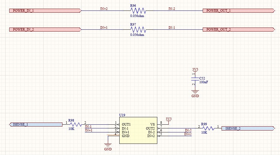
Discrete current sensing circuitry has been designed into our module to allow for live current monitoring of individual outputs as well as cumulative board current. Output current is sensed through a carefully selected shunt resistor that is then read by a current sensing IC. The current sensing IC outputs the reading as a voltage that can be sampled by the MCU and used for onboard diagnostics as well as external telemetry. When combined with our onboard voltage sensing, the current reading can be combined to estimate power consumption for individual devices and of the entire power distribution module.
Altium Schematics
Power Regulation
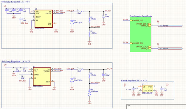
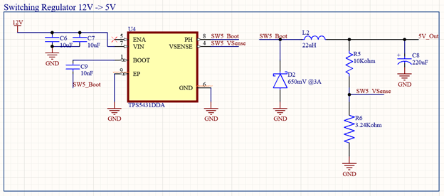
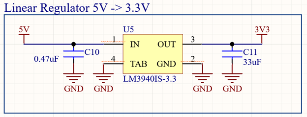
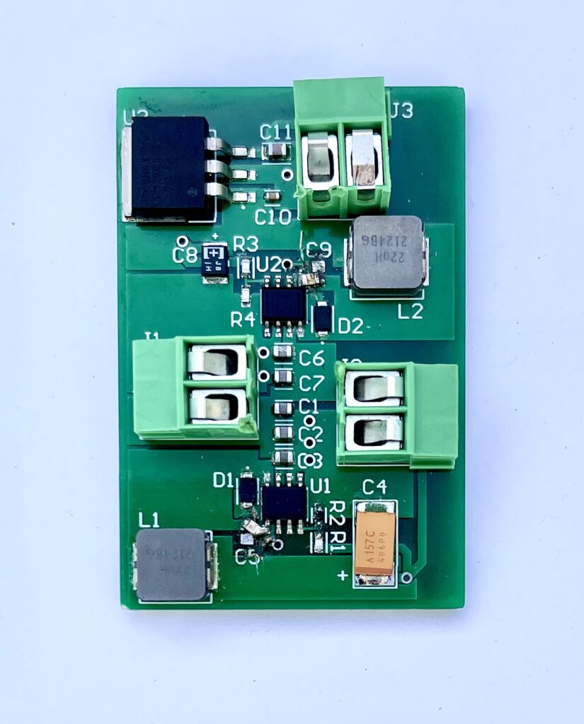
The power regulation module is a critical component of our power distribution system and properly regulates the battery voltage to provide the correct power for each of the various endpoints such as the radio and display as well as for the onboard components. Currently on the car, the existing PDM solution does not perform any voltage regulation for any of the outputs, so an external breakout board was required to regulate the battery down to 5 volts for most of the sensors on the car. Our power distribution system removed the need for the external breakout board reducing weight, space, and cost for power regulation on the car.
The main considerations for our power regulation design centered around these characteristics for the voltage regulators:
- Efficiency (Power Dissipation)
- Dropout Voltage
- Current Rating
- Operating Temperature Range
- Voltage Output’s Accuracy
- Input Voltage Range
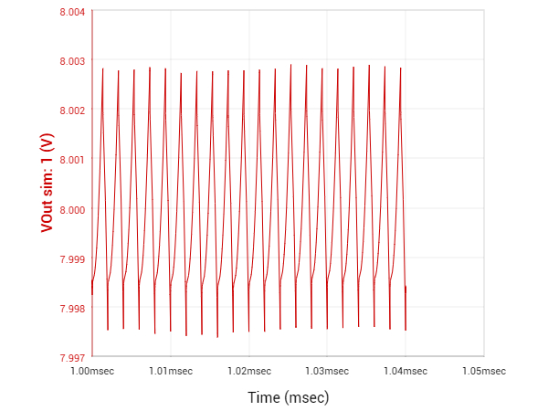
Based on these design considerations the power regulation module was designed to consist of two switching regulator circuits to regulate the battery (12 volts) down to 8 volts and 5 volts and one linear regulator circuit to regulate 5 volts down to 3.3 volts for the MCU, efuses and CAN transceiver.
Altium Schematics
Emergency Shut Down
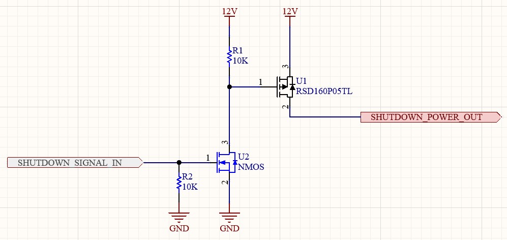
To protect the driver and vehicle in an emergency scenario, Formula SAE Rules require a shutdown circuit to cut power to the Fuel Pump and Ignition Coils. The shutdown is engaged when either the brake over travel switch or the main cockpit switch opens a circuit going back into the PDM. As a safety-critical function, this shutdown feature is implemented on our PDM solely with MOSFETs rather than relying on firmware executed in the MCU – maintaining reliability and speed of action. In the past, SR used bulky mechanical relays to meet the emergency shutdown requirements, however this new design greatly reduces mass, size, and cost.
Altium Schematic
Reverse Battery Protection
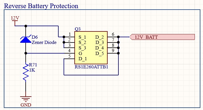
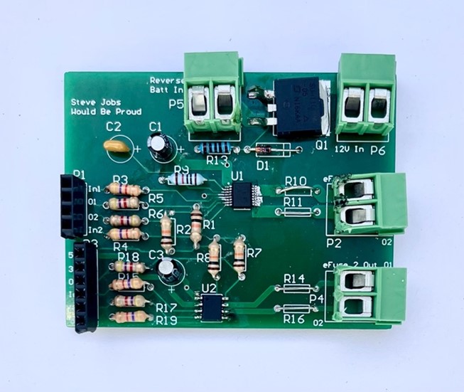
As SR is an interdisciplinary student team, team members of varying backgrounds and knowledge levels may work with and troubleshoot the electrical systems. The reverse battery protection circuit was included to ensure our design is as safe and user-friendly as possible. In the event our board is connected to a power supply that is in reverse polarity, the reverse battery protection circuit will engage ensuring our board and other downstream components are protected.
Altium Schematic
MCU
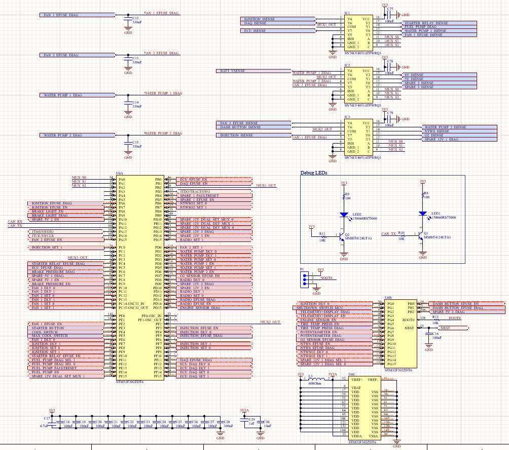
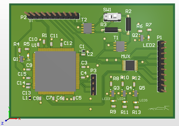
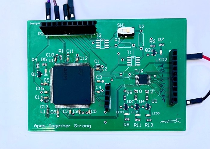
The MCU module functions as the central control system for our power distribution system. At its core is a specially chosen 144-pin ARM microprocessor that features peripherals to enable the sampling of 23 analog signals, monitoring of 23 digital signals, generation of 5 PWM signals, bi-directional communication over CAN, and control of 21 electronic fuse channels using over 60 digital pins. Of the total 144 pins, our solution utilizes 133. Surrounding the MCU itself are several multiplexing and input conditioning circuits to expand the MCU’s analog signal sampling capacity and convert specific signals to be MCU compatible respectively.
Altium Schematic
CAN
CAN (controller area network) is a message-based protocol designed to allow devices to communicate with each other without the need for a host computer. SR uses CAN as the standard protocol for communication between all the on-board equipment. As such, our design solution requires the ability to both read and send messages over a CAN network. The CAN module is designed to act as an interface between a microcontroller with CAN communication support and the CAN physical layer. The microcontroller utilizes the hardware in the CAN module to reliably send and receive messages. Examples of CAN messages broadcast by our device include battery voltage levels, the current draw of specific fuses, and fault events. We also monitor CAN messages from other vehicle components to make decisions about how to control certain vehicle endpoints.
Altium Schematic

Firmware
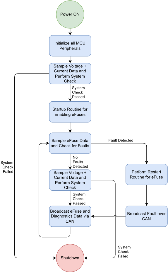
The control, monitoring, and communication capabilities of our power distribution module are managed by the firmware onboard the MCU. At its core is the use of FreeRTOS, a lightweight operating system that allows us to precisely schedule the execution of tasks, a necessary consideration when dealing with safety-sensitive applications such as ours. Using the functionalities within FreeRTOS, we regularly monitor diagnostic information from all fuses, switch inputs, and incoming CAN messages to make decisions about how to control the fuses. We also publish certain diagnostic information over CAN to be consumed by other devices on the vehicle and include self-test routines to verify that the PDM operates as expected during every power-up sequence.
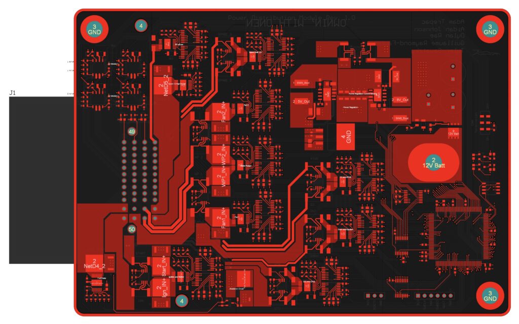
PCB Layout
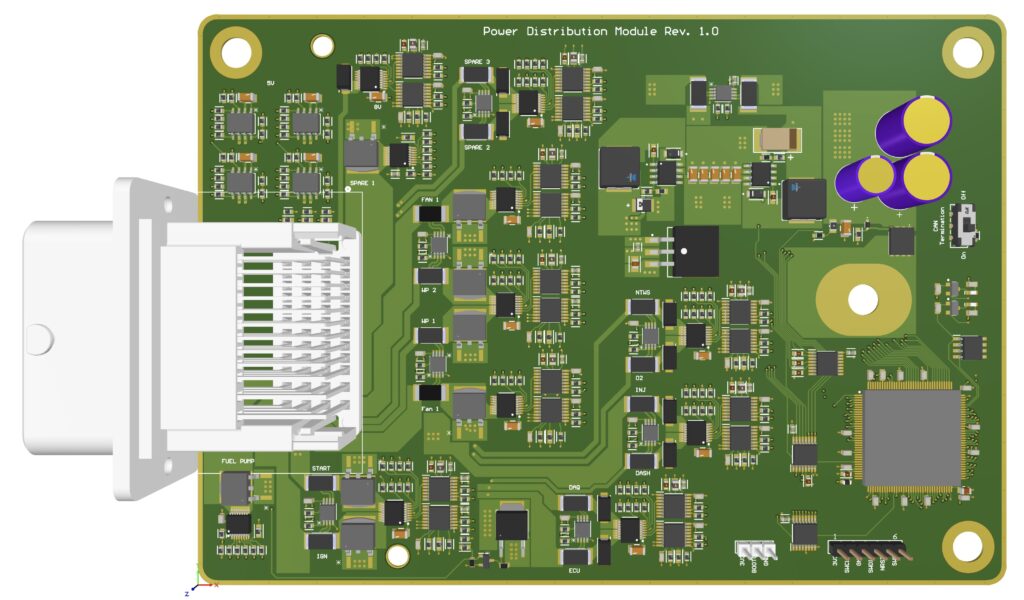
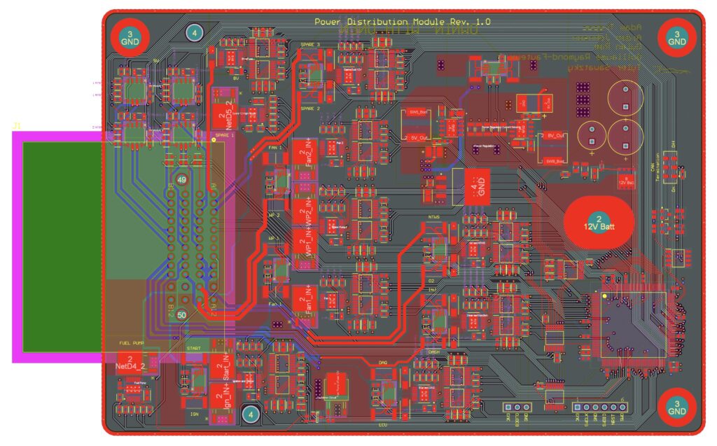
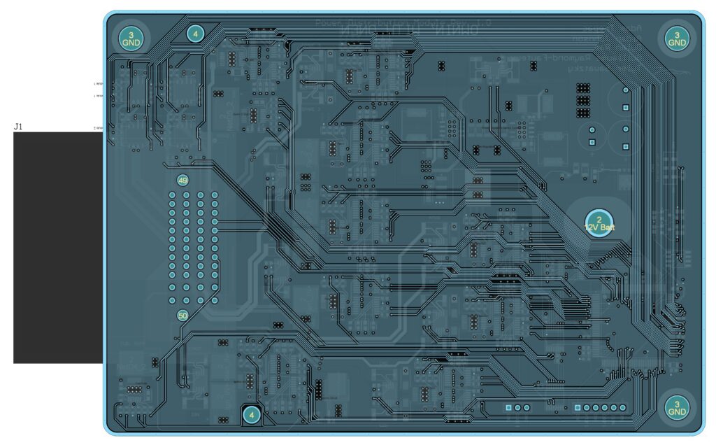
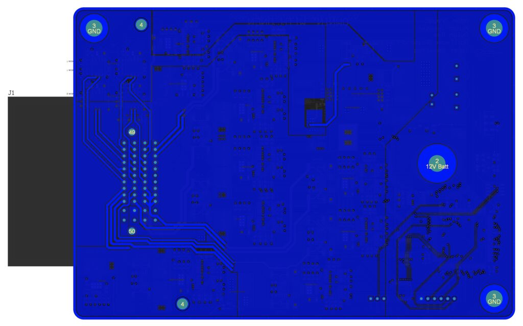
Understanding that there are many power and signal traces that require routing across the board, we required a 4-layer PCB for our final product. Our layer stackup is as follows:
- Top Layer: Used for component placement, routing between neighboring components, and routing of high-power traces
- Ground Layer: Provides convenient access to ground for all components, and reduces noise and interference between signals on the board
- Signal Layer: Used primarily to route signals from across the board to the MCU. Also includes a plane for 3.3V power
- Bottom Layer: Used primarily for routing power to eFuses and dissipating heat
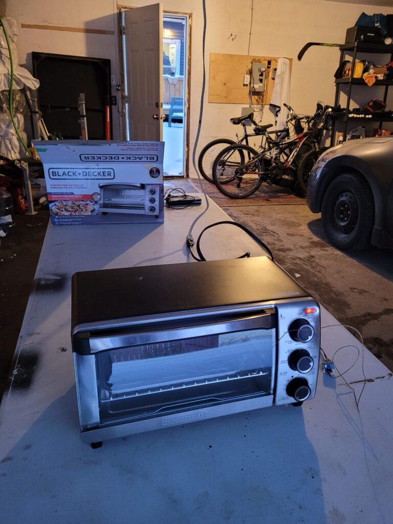
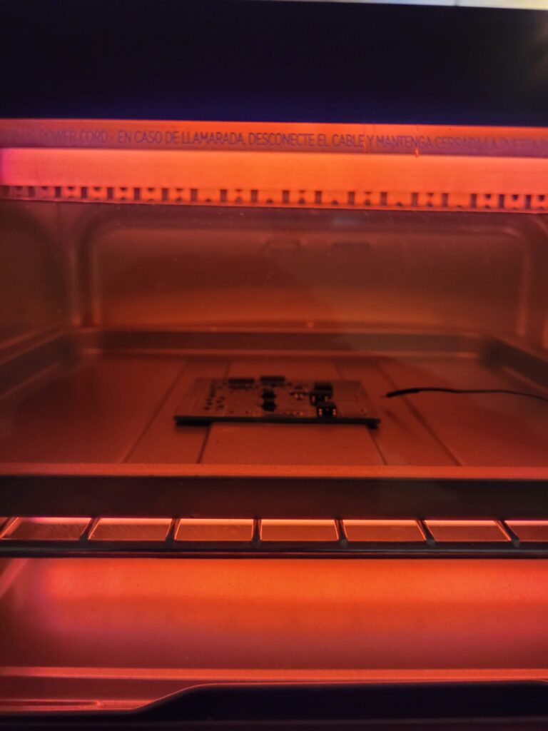
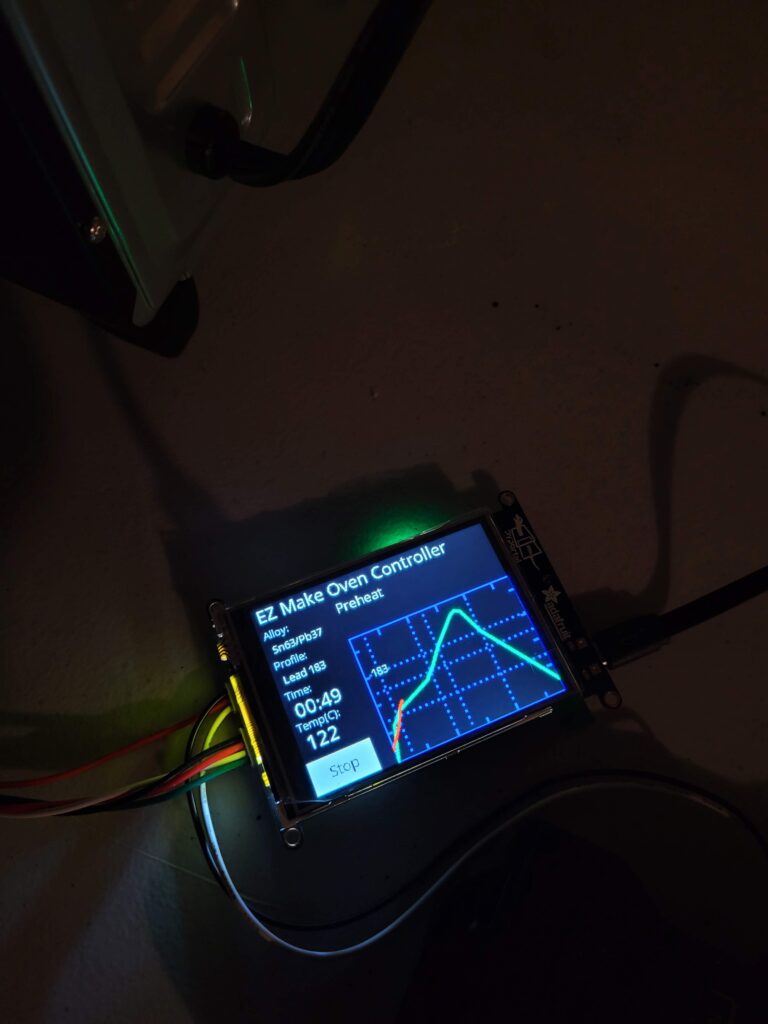
We chose to populate only one side of the board due to limitations in our soldering setup – a modified toaster oven was used to reflow solder the PCB.
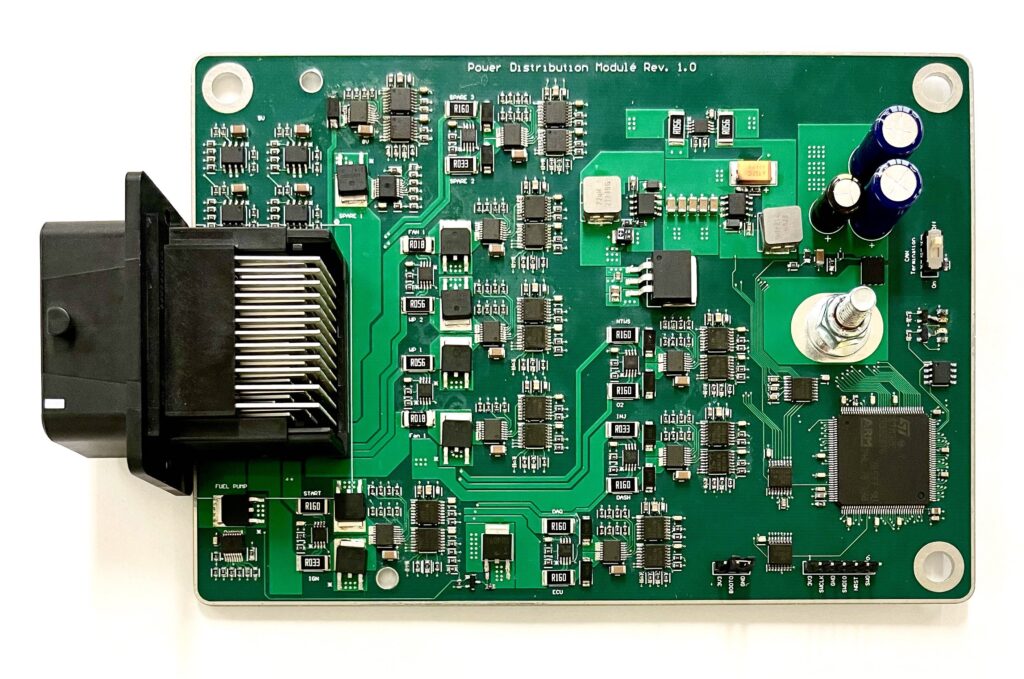
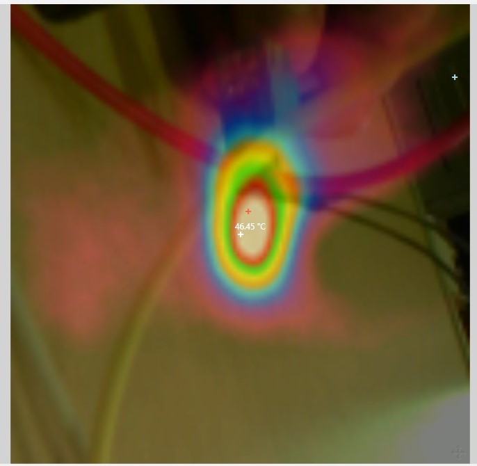
One major concern in the PCB design of this board was the thermal performance – up to 20 Amps are expected to flow through the board continuously. Multiple measures were taken to reduce resistance and improve heat dissipation, including using 2oz copper for the outer layers. Increased trace width and large copper pours were used in areas of high current flow to reduce resistance, and near components including eFuses and MOSFETs to absorb and dissipate the heat generated by their internal resistances.

Our Process

Initial Testing & Requirements Elicitation
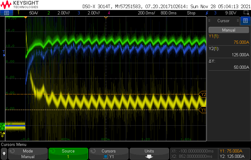
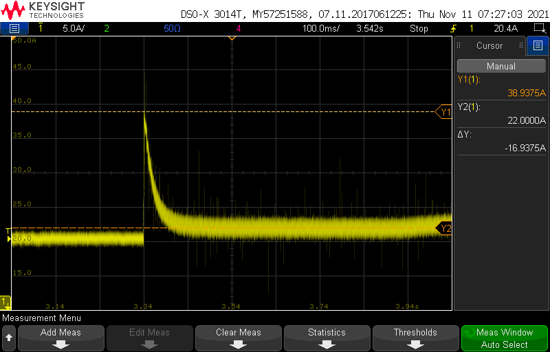
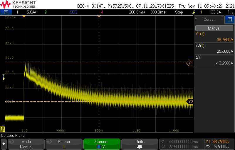
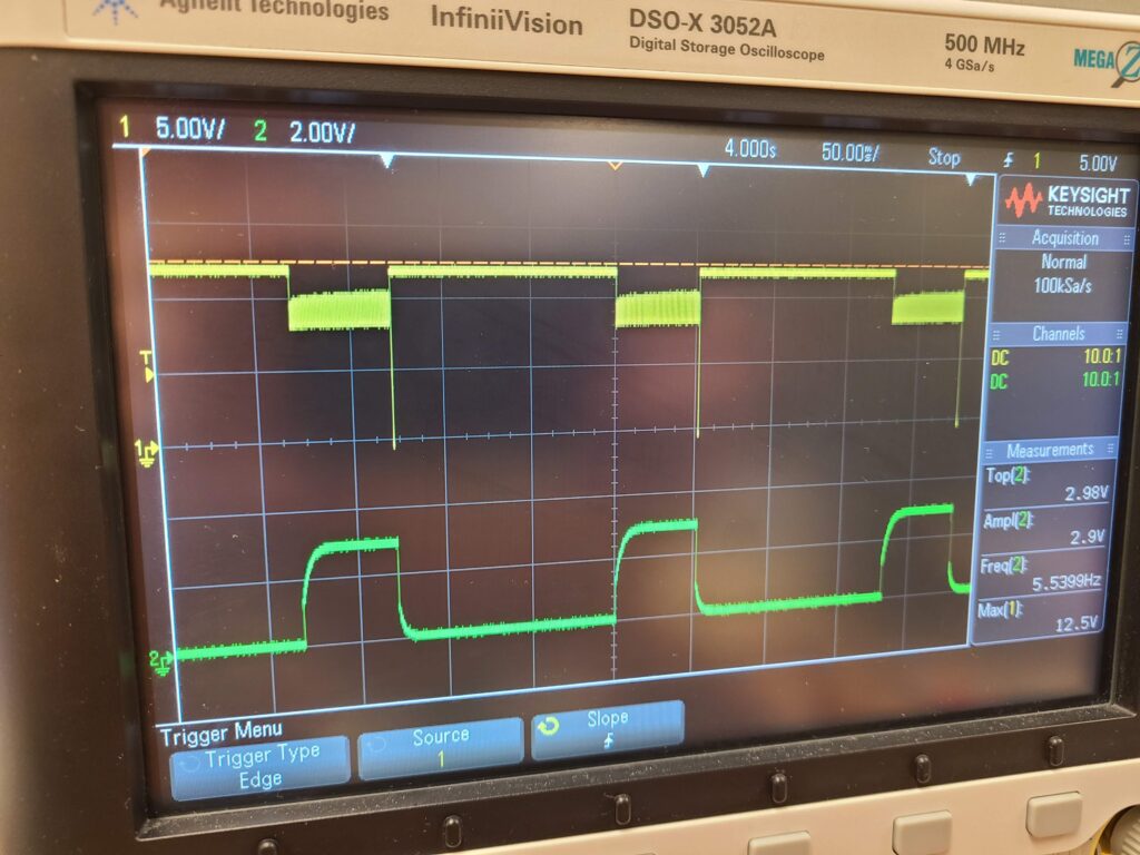
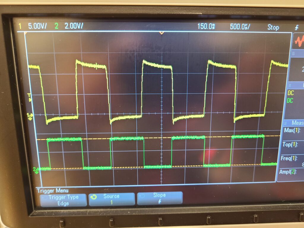
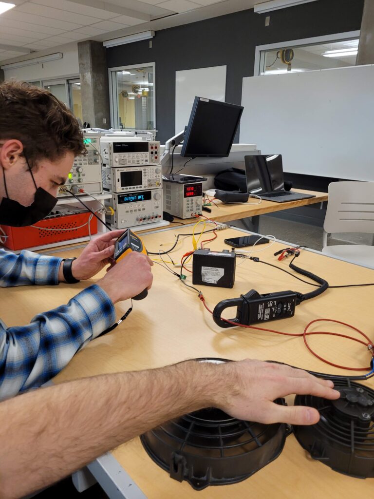
One of the first steps we took during this project was to investigate the exact current draw behavior of all major devices on the Schulich Racing car. Determining the typical operating current and in-rush current peaks and durations was of utmost importance to design the fusing circuitry connected to these devices. We created tests to operate the starter motor, as well as the various types of fans and pumps found on the vehicle and captured oscilloscope traces describing their current draw behavior under operating conditions. These traces were instrumental in guiding our decisions about fuse sizing, trip timing and power draw requirements.
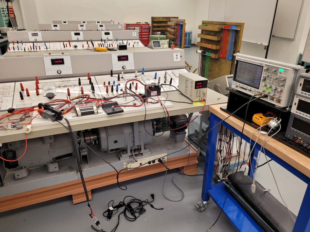
Oscilloscope Current Measurements
Test Module PCBs
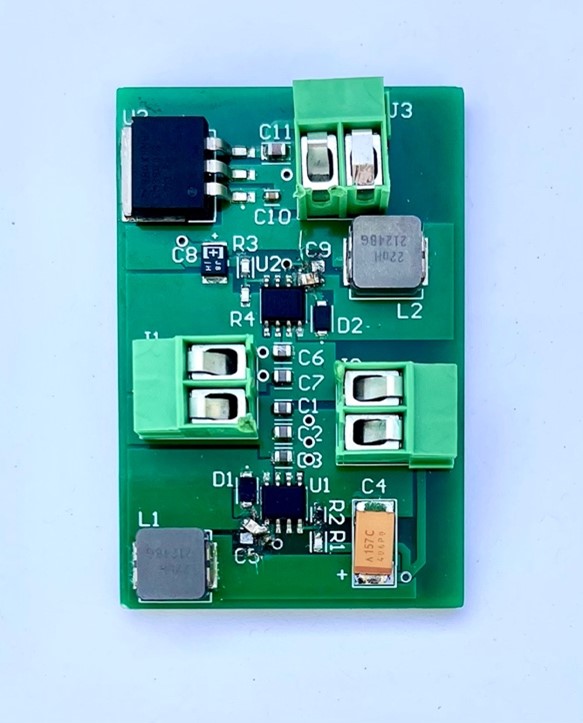
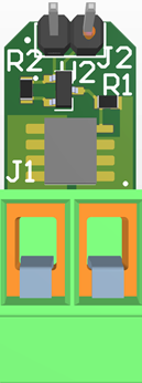
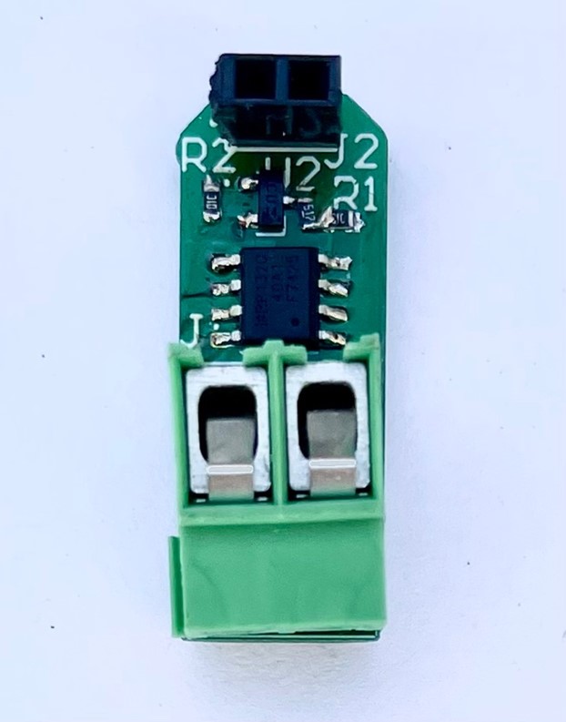
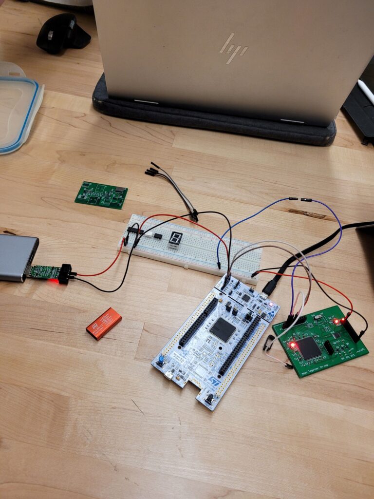
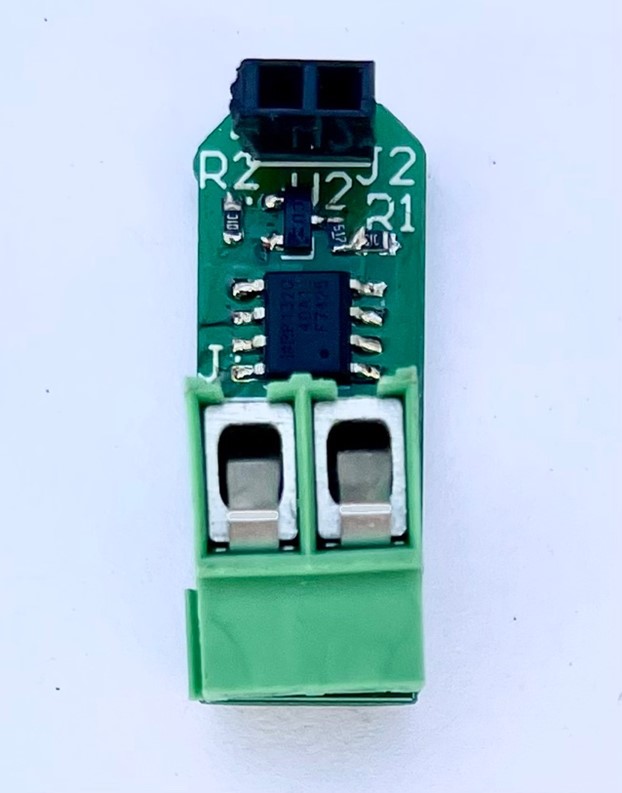
Since our final product would inevitably be large, complex, and expensive, we sought to break up our design into sub-modules that could individually be validated. These sub-modules included power regulation, electronic fusing, current sensing, emergency shutdown and MCU modules. We designed PCBs for each sub-module which could be tested to verify their standalone operation but could also be integrated with other sub-module PCBs to validate their operation when integrated as on the final product. Using this technique, we could iteratively improve upon each component of our design and be confident in our final integrated design without encountering excessive costs and difficult troubleshooting.
Test Module PCB Images
Power Regulation Module

MCU & CAN Module
Current Sense Module
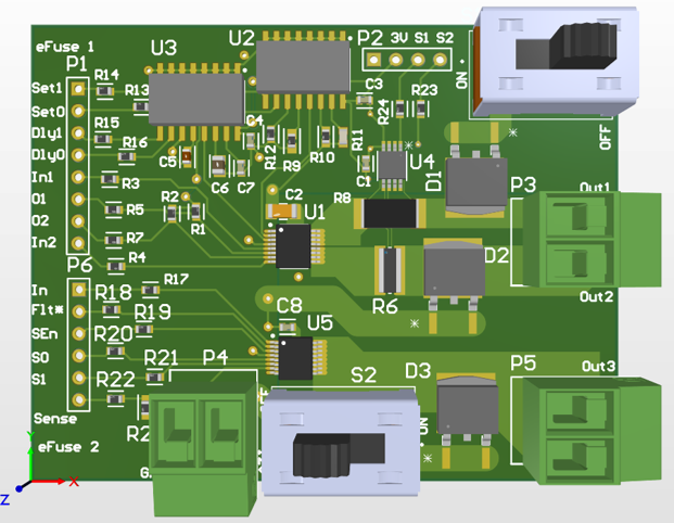

eFuse Module & Reverse Battery Protection

Shutdown Circuit
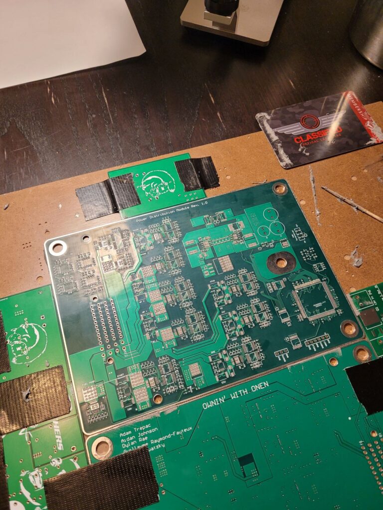
Final PCB
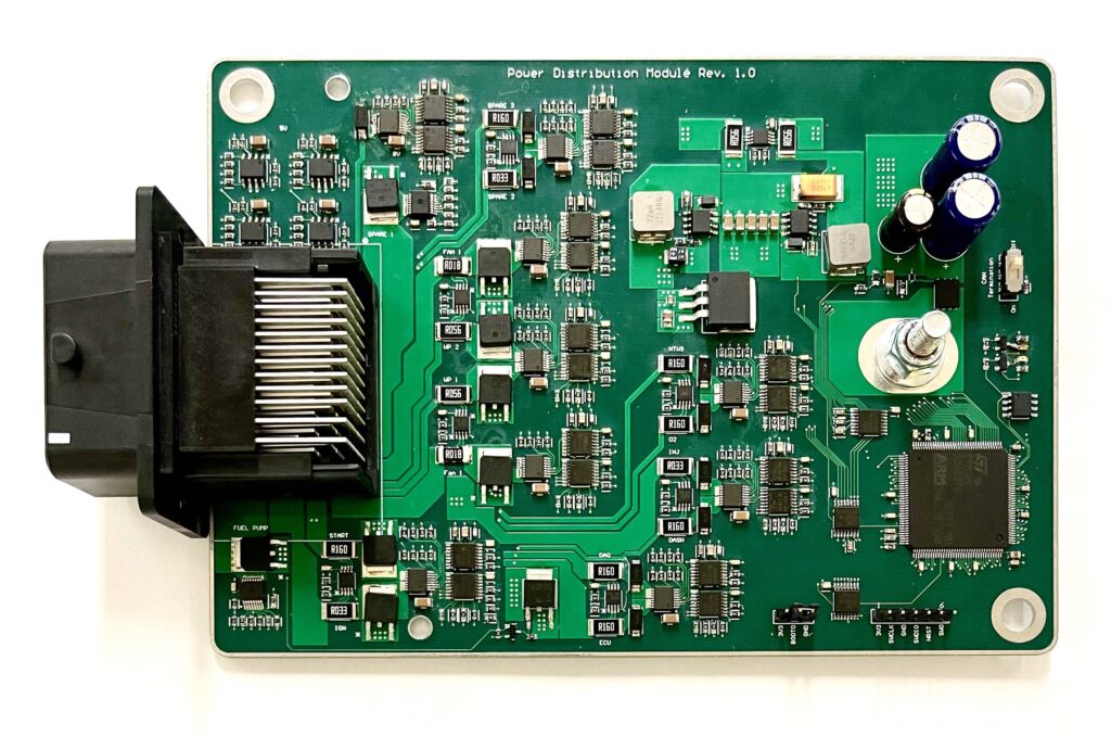
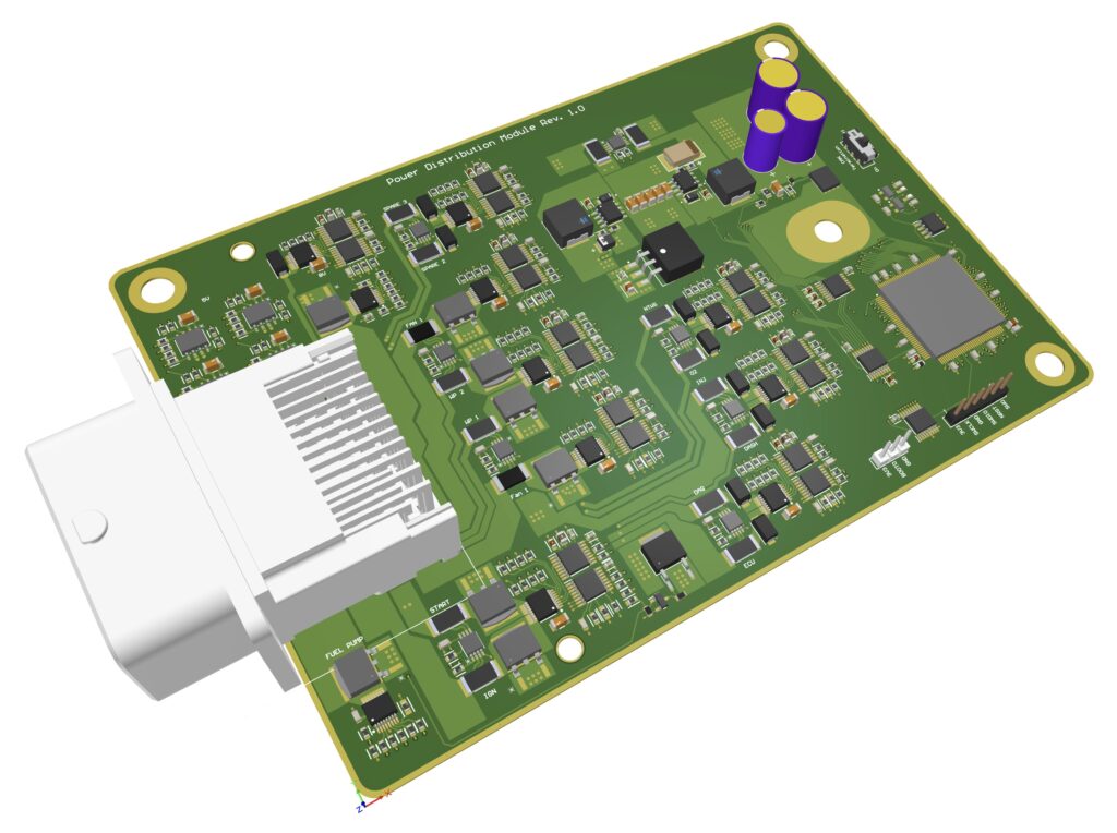
After being confident that each individual component operated as expected, we moved to replicate them on a final integrated PCB. To validate our final product, we generated a set of test cases that tested the technical specifications of our device as stated in our initial design proposal. Every aspect of the PDM, from successful manufacturing to basic functionalities such as fuse enabling and current monitoring, and finally to the complex routines which managed the PDM in real-time, were validated.
PCB Stats

420+ Parts

58 Unique Components

4 Layers

391 Nets

1031 Vias
Final PCB Schematic
Final PCB Test Plan
Partners & Sponsors


The success of our project would not have been possible without the support of our industry, academic and other sponsors. Our sponsor Schulich Racing was critical to our success and we would like to acknowledge Kevin Chow, Justin Tijunelis, Luke Fouad and other members on the team for dedicating their valuable time and resources in helping us test and progress our project.
We also want to thank our faculty advisor Dr. Denis Onen who was willing to work closely with our team and offer insights, feedback and equipment that were instrumental in our success. Additional thanks to Elham Sadeghabadi for supporting us throughout this course.
Finally, we would also like to thank JLCPCB for their sponsorship of our final PCB as well as our sponsor Altium Designer that enabled us the ability to build our PCBs using industry-standard software.
Gallery
Power Regulation

MCU & CAN

EFuses & Current Sensing

Emergency Shutdown
Soldering
