Project Category: Civil
Join our presentation
Join us in our ZOOM Room on April 5, 2022, to learn more.
For any issues and concerns accessing this room, please contact jashandeep.jassal@ucalgary.ca
About our project
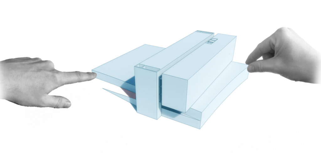
In the rapidly urbanizing environment of Calgary, the search for affordable housing with sufficient amenities nearby is getting harder and harder. The Symons Valley Mixed Use Development project aims to help alleviate that problem, by combining low-cost housing and commercial spaces into one building. The combination of uses and material choices for this building will help reinforce a relatively new type of development in Calgary which benefits the community as a whole.
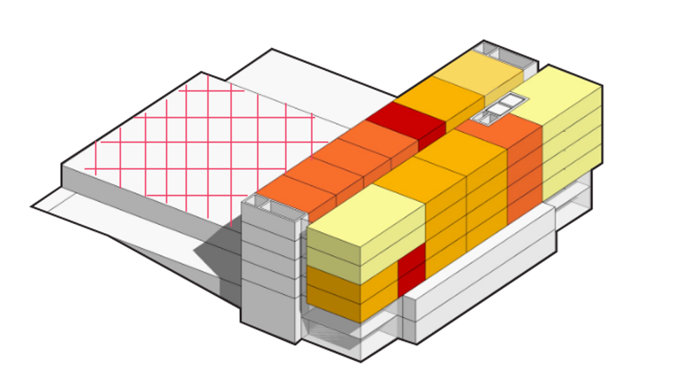
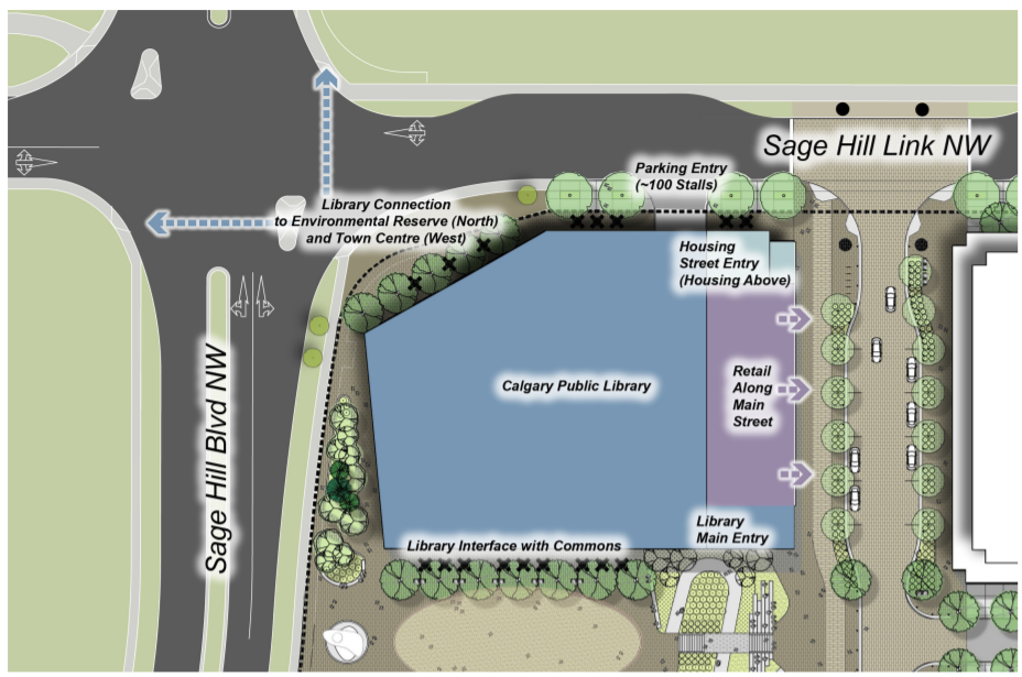
The Symons Valley Mixed Use project is located in the northwest Calgary community of Sage Hill and will include a combination of affordable-housing residential units, a public library, an adaptable community events area, commercial retail units, daycare, underground parking and outdoor public plaza.
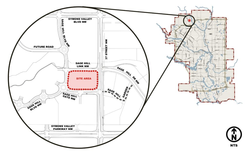
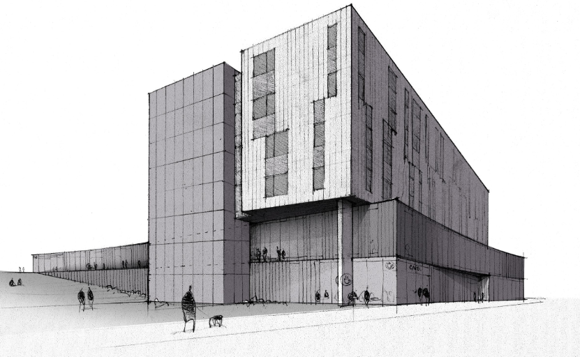
This new development is intended to have direct access to a future hub of the Bus-Rapid-Transit (BRT) network and will serve as a central community hub, integrating affordable housing into the surrounding community.
The ultimate objective of this project is to design a structural system that balances the low-cost and proven nature of traditional building materials and techniques like concrete, and implementing sustainable building materials such as engineered wood. The scope of design includes:
- Interior columns and vertical loading systems for the residential and commercial spaces.
- Lateral loading systems for the entire building.
- Below-grade foundation design.
- Material usage cost and impact assessment.
- Zoning, use and justification of the 2nd floor roof space.
With the successful completion of these objectives, an overall vision for the first phase of sustainable and low-cost development in Symons Valley can be realized.
Meet the S3 Constructors Team Members
Details about our design
Problem outline
The design aims to produce a cost-effective, sustainable, appealing, and code-compliant design satisfying the vision provided by the client and architect. Potential solutions were outlined and assessed in a multitude of ways such as structural strength analysis, environmental analysis of construction materials, and feasibility studies into building use.
Sustainable design of future buildings is a key part in efforts to reduce overall environmental impact of the construction industry. Approximately 40% of global CO2 emissions originate from building operations (28%) and construction (12%). In our scope, we aimed to reduce the initial impact of building construction by exploring alternative material choices for this building, as well as looking at the end-of-life disposal/re-use. The focus of this choice was put on the low-cost residential tower, as its repetitive housing units make it a template building that can easily be used in other projects and will serve as a pioneer of sustainable construction in the rapidly developing community of Symons Valley.
Of course, any building has to be designed to withstand all expected forces during its lifetime. The loading paths for vertical and horizontal loads such as dead load, live load, wind and snow were evaluated for each potential solution to produce a final design that integrates the aspects of low-impact construction and structural strength for the residential tower, commercial and community spaces, and the underground parkade.
Another objective of this design that was studied was the use of the 2nd floor roof area. A variety of uses were considered, such as a green space to further help offset carbon emissions, solar PV panels to provide electricity for building operation, and a large active living and communal space to attract attention.
Structural system and material choice – Residential tower – Floors 4-6
Material choice and structural systems
The 3 main options assessed for material choices for the residential tower were methods consisting of primarily: Steel, Reinforced concrete, engineered wood. The rationale behind these options and the final choice is discussed below:
Composite slab and steel beam/column design:
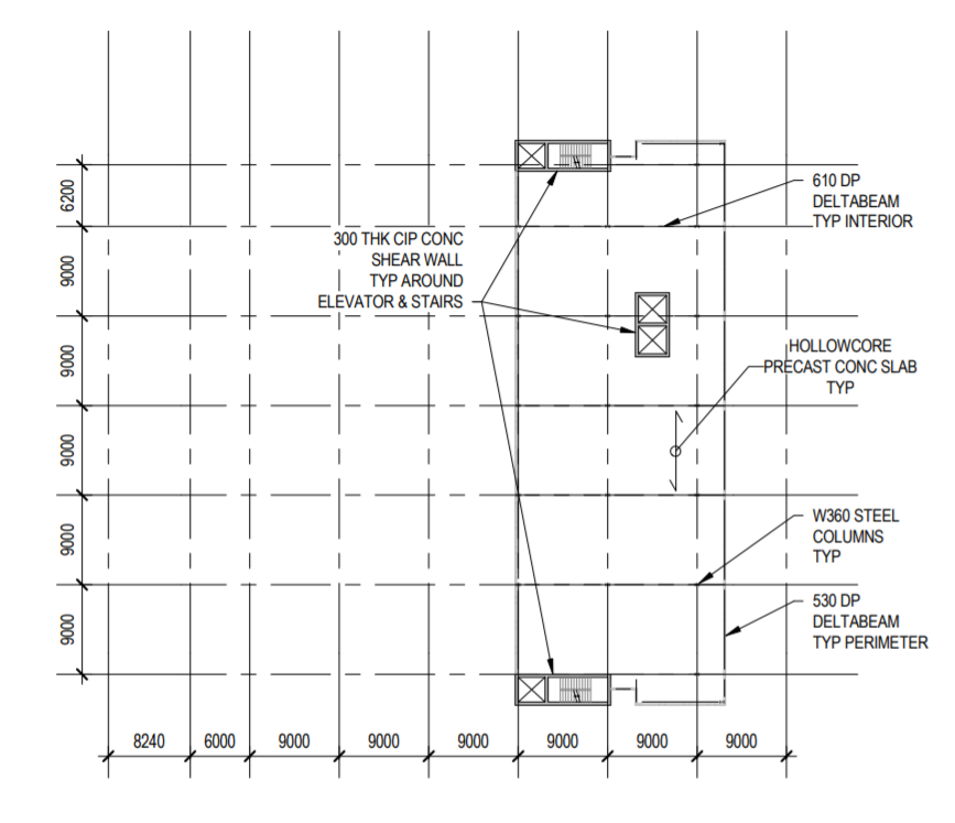
The first design considered consisted of commercially available steel components such as composite floor slabs and I-beams for vertical and horizontal members. The load transfer path would be from a one-way CANAM P-3623 composite floor slab from the CANAM Steel Deck Catalog [3] with a 50mm concrete topping, to 400mm deep joists, to W460x89 beams, and finally W360x72 columns.
A typical steel structural drawing for the residential tower seen in the preliminary drawings section in the photo gallery.
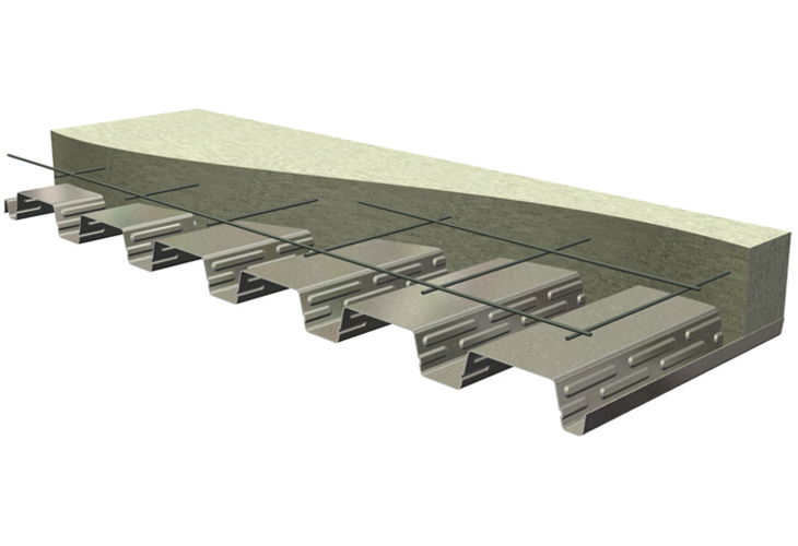
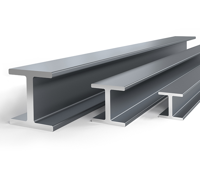
Although it was the most cost-effective solution in terms of material and assembly cost, the initial production of steel is quite carbon intensive, and can have the potential to emit other pollutants into the atmosphere, such as Carbon Monoxide, Sulfur and Nitrogen Oxides, and particulates. The estimated embodied carbon in this design is 112 tons of CO2 [4]. Its potential for re-use also requires additional heat to scrap and melt down the steel for future re-use.
Traditional reinforced concrete slab and column design:
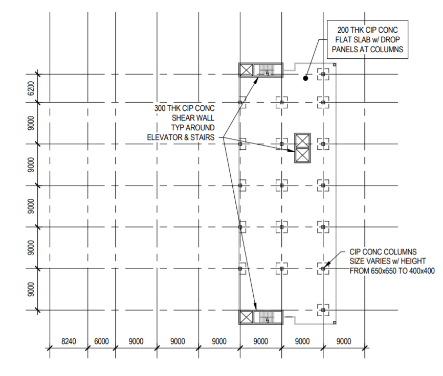
This design uses the tried-and-true method of C-1 class concrete with steel reinforcement to build a 200mm thick concrete 2 way slab, with 450mm-600mm columns and drop panels to transfer vertical loads.
A typical RC slab design for the residential tower can be seen in the preliminary drawings section in the photo gallery.
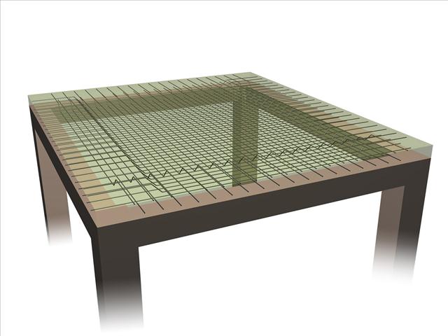
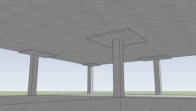
While being close to steel in terms of overall cost of materials and labor, it is by far the most carbon intensive option, as cement production emits a large amount of CO2, with our design having an estimated output of 770 tons of CO2 [4]. Concrete is also the least salvageable and most energy intensive material to demolish and dispose, as its removal poses a large risk of dust pollution, while requiring heavy machinery. Also, concrete structures become more important with relatively tall buildings due to its compressive strength but is not really needed in a low-rise setup of this project (6 stories).
Engineered wood and lumber:
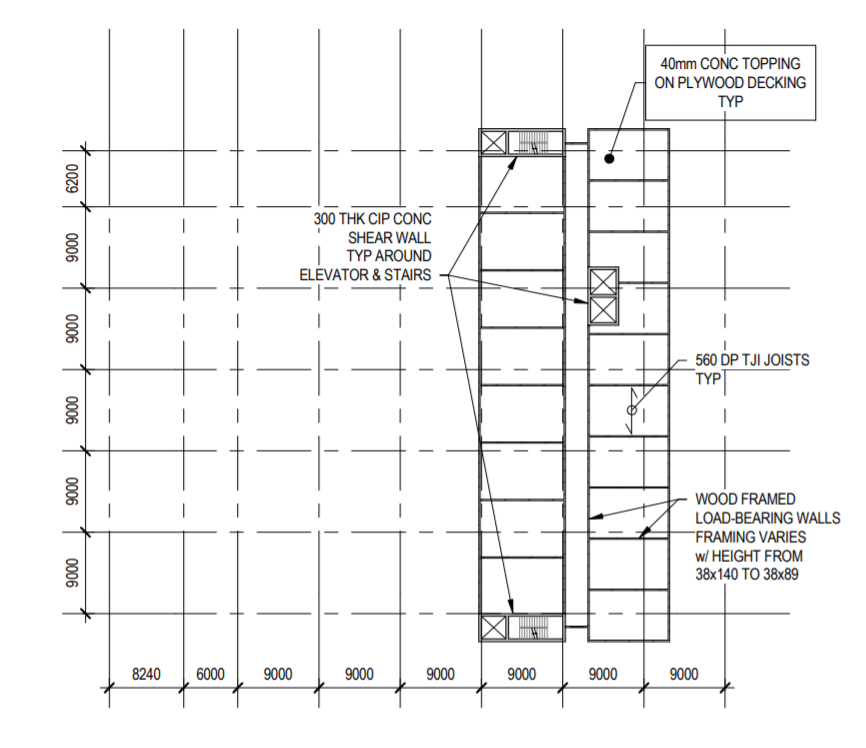
The last option evaluated was using commercially available TJI joists and wood products for structural system. The load path is consists of 16mm plywood flooring, to various 560DP TJI joints, to lumber load-bearing stud walls of different sizes. This wood construction would be tied into the concrete shear core using extra stud walls and steel brackets set into the concrete during pouring.
A typical wood structural section can be seen for the residential tower can be seen in the preliminary drawings section in the photo gallery.
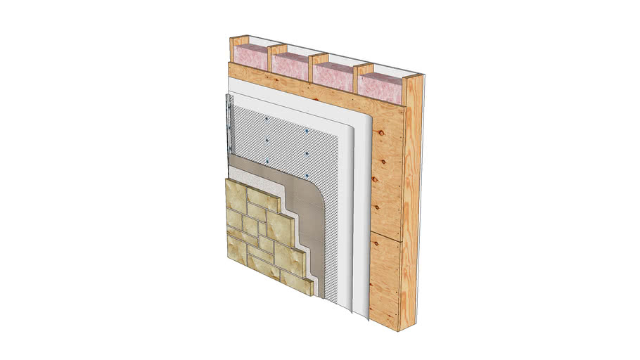
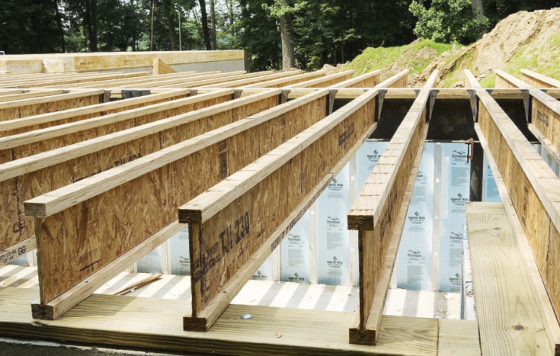
The timber option was the most expensive, but timber used in the construction acts as a net carbon sink over the course of its lifetime which could potentially help the design achieve certain levels of LEED certification if combined with other environmentally friendly systems. Lumber’s ease of repairability, replaceability, and end of life salvage value also make it an attractive option.
Chosen system – Option 3: Engineered wood and lumber
Cost breakdown by material (tower only)

After considering the overall impacts of each design, option 3 was chosen. Timber construction allows for simpler assembly, and embodied carbon savings may assist in LEED certification of the building moving forward. This design is estimated to sequester approximately 19 tons of Carbon from the atmosphere, which is a significant impact reduction from the steel and concrete designs.
The use of wood in the residential floors also allows for a simpler but laborious system, lower dead loads on the floors and columns below, and a lower environmental impact. Use of light wood-paneled shear walls removed the need for additional concrete wall construction, and application of engineered timber joists reduced overall material requirements.
The cost for the timber design is also the highest, but this increased cost was justified with the amount of carbon it saved and acting as an example for future buildings in the community and Calgary as a whole to follow in the future.
Design Specifications
The residential timber design is based on standard stud walls, using structural-grade lumber to maintain 400mm spacing with 3.6m floor heights while satisfying resistance requirements as provided in the National Building Code of Canada. The floor was determined to be 16mm plywood topping, with a 10mm roof topping. Engineered floor joists prevent significant deflections to maximize occupant comfort while minimizing member size. Plywood sheathing and timber chords provide lateral load resistance, transferring loads to concrete elevator and stairwell shafts. Intermediate tied-down wood-paneled shear walls were provided to reduce loads on the shear diaphragm, preventing oversizing of diaphragm elements and eliminating the need to provide additional concrete shear walls. This structural system effectively meets both lateral and vertical load requirements as described in the NBCC to ensure durability, safety, and occupant comfort.
The full set of structural drawings for the a typical tower section can be found in the ‘Structural Drawings Package – Above Grade’ in the photo gallery.


Structural system and material choice – Commercial/Community space – Floors 1-2
Structural system choice
The primary structural system consists of a two-way slab system for the lower two floors much like option 2 evaluated for the residential tower. The majority area slabs are 300mm thick and cover an area of 9mx9m excluding the exterior spans. These supported on columns varying from 650mm x 650mm under the residential tower, and 450mm x 450mm everywhere else, with 4.5m x 4.5m drop panels. Lateral resistance is provided by a 300mm RC shear core consisting of two stairwells and an elevator shaft spanning the entire height of the building. This design allows for a lower ceiling height and ceiling obstructions that would come with a beam and girder design. This allows for simpler and faster M&E installations, easier slab penetrations and fireproofing.
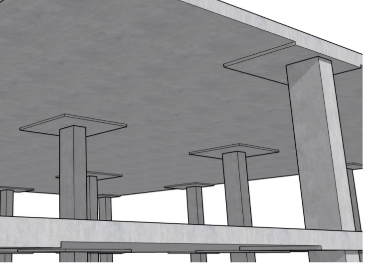
Structural drawings and slab/column specifications can be seen in the ‘Structural Drawings Package – Above Grade’ in the photo gallery.
Material choice
The lower two floors of the building were chosen to be built with concrete due to the presence of larger open spaces and the need to accommodate loads from the residential tower above. The lower floors will use a high fly ash mix like Eco Pact Prime from Lafarge [4]. This fly ash concrete grants reductions of CO2 emissions of up to 60% when compared to the baseline CO2 intensity of standard concrete of 750 kg CO2/t. For this design, EcoPact Prime [5] reduces emissions from 6,300 tons of CO2 to 3780 tons of CO2 [4].
Structural system – Parkade and foundation – Floor 1
For the parkade and foundational sections, our design solutions are effective based on the evidence collected from the provided geotechnical report by Tetra Tech [6]. From the geotechnical report, the soil underneath the building was mostly clay-based which is a suitable soil for the parkade slab on grade since the water table is located well below grade. Clay soil, which exemplifies excellent compression pressure, does tend to fail with the presence of water however, the water table is well below the location of the slab on grade, thus allowing for an effective slab on grade design.
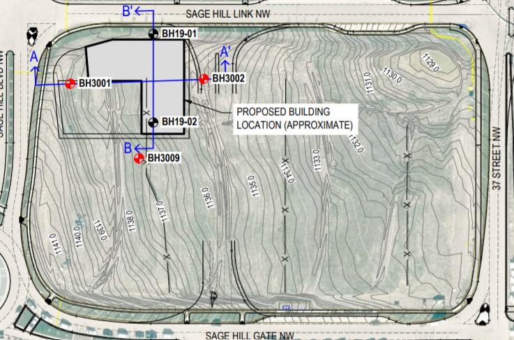
Additionally, the foundation of the building transfers its loads directly to the earth’s bedrock, the most effective and practical method of supporting a building due to bedrock’s durability and guaranteed strength dependency regardless of other mitigating factors such as water presence. Overall, this warranted an effective solution of cast-in-place rock-socket pile foundation for this design issue.

The underground parkade was is designed to be built with EcoPact Prime [5] concrete cast in place sections for both the slab on grade and shear wall. A 125mm slab on grade was designed to provide a surface for parked vehicles. It was feasible to design a thin slab as the applied loads caused very little compressive and tensile stress throughout the slab. Another benefit of the low applied loads is the need for minimal reinforcement, which resulted in 3-10M bars per meter of slab in each direction. The parkade shear wall are sized to be of 400mm thickness with 10M Bars at variation of spacing for the horizontal (shear) and vertical (moment) reinforcement and spans the entire length of the wall. This reinforced concrete structure will have substantial resistance to the lateral soil pressure located on the southwest corner, entire west wall, and northwest corner of the building. Though the remaining parkade shear walls are not exposed to soil, the walls are sufficient to resist lateral wind pressure which is minimal compared to the soil pressure.
Lastly, the building will be supported on cast-in-place rock-socket piles located underneath sections of pilaster on the exterior as well as columns for the interior sections of the building sections of the building. Due to the high presence of clay as well as high gradation of bedrock (13 meters from grade), cast in place rock socket piles was the most sensible option for this project. The pile design parameters (listed below) provide a suitable skin and bearing resistance when foundations are embedded into the bedrock. Additionally, piles should be installed with casing as there is an existence of the water-table (6.5 meters from grade) half-way from at grade to bedrock (13 meters from grade).

Structural drawings for the parkade and foundation design can be seen in the ‘Structural Drawings Package – Slab on Grade’ and ‘Structural Drawings Package – Shear Wall’ in the photo gallery.
Use and loading – 2nd floor roof
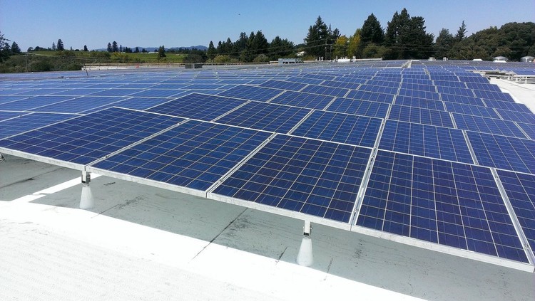
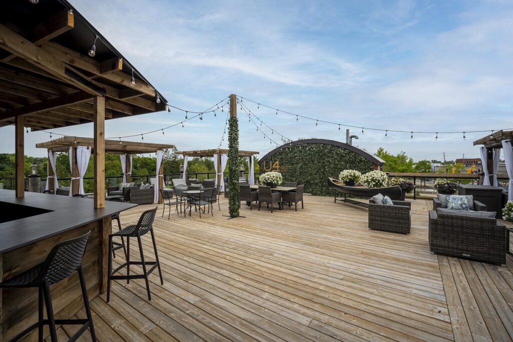
A secondary objective of this design that was studied was the use of the 2nd floor roof area. A variety of uses were considered, such as a green space to further help offset carbon emissions, solar PV panels to provide electricity for building operation, and a large active living and communal space to attract attention.
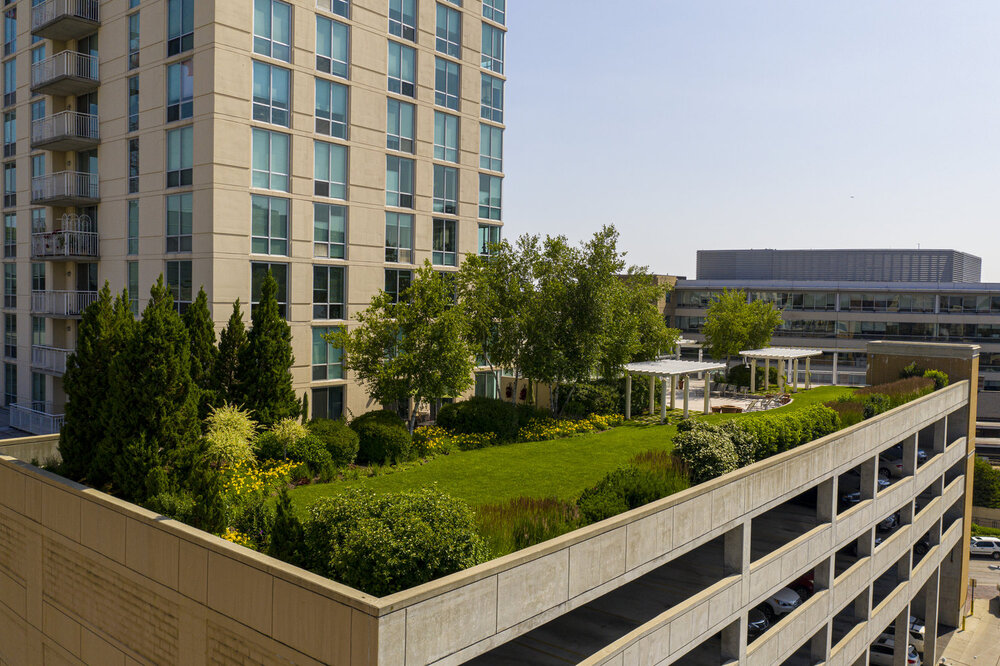
An outdoor green space has massive potential to be an attractive place to sit and enjoy, especially for residents, but its primary focus as a carbon sink is limited due to its Calgary location and climate. The range of plants available year-round that are low maintenance is quite limited, and the snowfall average would mean frozen ground and covered plants.
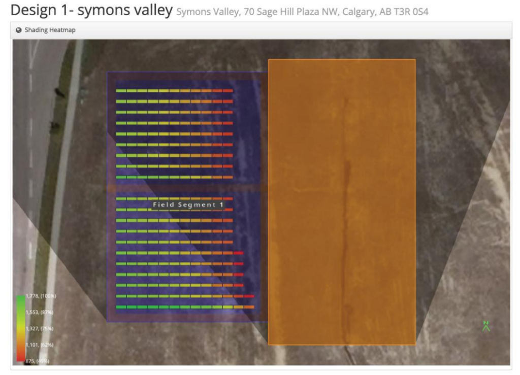
Solar energy from photovoltaic panels is another great option, as it helps reduce building emissions, and could help subsidize the cost of electricity for the building’s residents and commercial operators, albeit with a high upfront cost. A feasibility study was conducted using the HelioScope [7] software to determine PV efficiency of the area’s orientation. As the residential tower is towards the East side of the roof, a good portion of the panels are blocked after midday, giving a utilization factor of only 58%. This was determined to not be financially viable.
Another option was to zone the roof space as an active living/ communal space. This would allow for outdoor seating for restaurants, an open-air gym, and possibly winter options such as a rooftop ice rink for the colder times of the year. This option allows residents of this and nearby areas to enjoy more amenities and further push the vision of a community centre, as well as local businesses to make money. In a 2018 survey of the community [2], the desire for more community spaces such as recreational facilities was brought up when discussing new developments for the site, furthering the attractiveness of this option.
The final option chosen for area usage was a combination of options 1 and 3. For loading purposes, the area would be considered an active space with a live load of 4.8 kPa + allowances for M&E and infrastructure dead load. With this zoning, the area has the potential to be used as an outdoor gym and recreational area, with sections for outdoor/semi-enclosed patios and restaurants. This loading allowance would enable a rooftop green area as well, but its primary function will not be to act as a carbon sink, but as a walkable garden for building aesthetics.
Validation of design solutions
The following codes and standards were used to validate the designs in this project:
- National Building Code. (2019). 2019 Alberta Edition.
- CSA Group. (2014). CSA A413-14 (Parking structures).
- CSA Group. (2019). CSA 089-19 (Engineering design in wood).
- Construction, C. I. (2000). In Handbook of Steel Construction Seventh Edition (pp. 4-41).
- CSA Group. (2019). CSA A23.3:19 (Design of concrete structures).
Design calculations were done via Microsoft Excel, and all critical calculations were verified by the academic and industry advisors, Dr. Neil Duncan and Mr. Chris Lenzin respectively.
Final estimated cost
The final cost estimate for the building is $21,132,000. Prices were obtained via supply quotes from LaFarge, Harris Rebar, Northland Wood, and RSMeans. Please note that this value is not to be used as an actual construction estimate, and does not include current market labour/equipment or overhead costs.
Partners and mentors
S3 Constructors would like to thank our academic advisor Dr. Neil Duncan, and our industry advisor Mr. Chris Lenzin from DIALOG for their guidance and advice throughout this project.
Our photo gallery
Preliminary Drawings
Structural Drawings Package – Above Grade
Structural Drawings Package – Slab on Grade
Structural Drawings Package- Shear Wall
References
- DIALOG. (2020, June 5). Symons Valley Centre SD Floorplans. Calgary, Alberta, Canada.
- City of Calgary Symons Valley Centre (n.d.): Retrieved from https://engage.calgary.ca/symonsvalley
- CANAM. (n.d.). Steel Deck. Retrieved November 17, 2021, from https://www.canamconstruction.com/wp-content/uploads/2014/12/canam-steel-deck-catalogue-canada.pdf
- Holcim. (n.d.). Ecopact – The Green Concrete. Retrieved from https://www.holcim.com/ecopact-thegreen-concrete
- Holcim (n.d.) Building with EcoPact. Retrieved from https://www.lafarge.ca/sites/canada/files/atoms/files/building_with_ecopact.pdf
- Tetra Tech Canada Inc. (2020). Geotechnical Evaluation Proposed Symons Valley Centre – Phase 1A Northwest Portion of 251 Sage Hill Boulevard NW Calgary, Alberta. Calgary, Alberta.
- HelipScope Solar Design Software (n.d.) Report drafted from https://www.helioscope.com/
- https://www.metaldeck.com/plb-formlok-punchlok-verco-metal-decking.htmlsteel beam:
- https://www.servicesteel.org/products/structural-steel/structural-shapes/beams/i-beams
- https://www.engineersdaily.com/2016/04/difference-between-one-way-two-way-slabs.html
- https://structurepoint.org/pdfs/Two-Way-Concrete-Slab-Floor-With-Drop-Panels-Design-Detailing.htm
- https://bearcreek.co/2018/02/21/the-sun-is-shining-framing-a-floor/
- https://3dwarehouse.sketchup.com/model/acbfe350-888e-43de-b70f-1ff811ce7414/030900223-Wall-system-Adhered-stone-wood-studs-plywood-sheathing-2-layers-building-wrap-lath
- :https://ecogardens.com/green-roofs
- https://www.archdaily.com/934122/what-are-the-good-the-bad-and-the-ugly-of-rooftop-solar-photovoltaic-systems
- https://kawarthanow.com/2022/02/21/its-business-laughter-and-happily-ever-after-at-u4-rooftop-patio-bar-in-downtown-peterborough/


